Manual
Page 1
GA-P55-USB3 LGA1156 socket motherboard for Intel® Core™ i7 processor family/ Intel® Core™ i5 processor family User's Manual Rev. 1001 12ME-P55USB3-1001R
GA-P55-USB3 LGA1156 socket motherboard for Intel® Core™ i7 processor family/ Intel® Core™ i5 processor family User's Manual Rev. 1001 12ME-P55USB3-1001R

Manual
Page 2
Motherboard GA-P55-USB3 Dec. 24, 2009 Motherboard GA-P55-USB3 Dec. 24, 2009
Motherboard GA-P55-USB3 Dec. 24, 2009 Motherboard GA-P55-USB3 Dec. 24, 2009
Manual
Page 4
Table of Contents Box Contents...6 Optional Items...6 GA-P55-USB3 Motherboard Layout 7 GA-P55-USB3 Motherboard Block Diagram 8 Chapter 1 Hardware Installation 9 1-1 Installation Precautions 9 1-2 Product Specifications 10 1-3 Installing the CPU and CPU Cooler 13 1-3-1 Installing the CPU 13 1-3-2 Installing the CPU ...
Table of Contents Box Contents...6 Optional Items...6 GA-P55-USB3 Motherboard Layout 7 GA-P55-USB3 Motherboard Block Diagram 8 Chapter 1 Hardware Installation 9 1-1 Installation Precautions 9 1-2 Product Specifications 10 1-3 Installing the CPU and CPU Cooler 13 1-3-1 Installing the CPU 13 1-3-2 Installing the CPU ...
Manual
Page 5
...75 4-6 Smart 6™ ...76 4-7 Auto Green...79 4-8 eXtreme Hard Drive (X.H.D) j 80 Chapter 5 Appendix...81 5-1 Configuring SATA Hard Drive(s 81 5-1-1 Configuring Intel P55 SATA Controllers 81 5-1-2 Configuring GIGABYTE SATA2 SATA Controller 89 5-1-3 Making a SATA RAID/AHCI Driver Diskette 95 5-1-4 Installing the SATA RAID/AHCI Driver and Operating System 96 5-2 Configuring Audio...Recording 111 5-2-4 Using the Sound Recorder 113 5-3 Troubleshooting 114 5-3-1 Frequently Asked Questions 114 5-3-2 Troubleshooting Procedure 115 5-4 Regulatory Statements 117 j Only for P55 Chipset. - 5 -
...75 4-6 Smart 6™ ...76 4-7 Auto Green...79 4-8 eXtreme Hard Drive (X.H.D) j 80 Chapter 5 Appendix...81 5-1 Configuring SATA Hard Drive(s 81 5-1-1 Configuring Intel P55 SATA Controllers 81 5-1-2 Configuring GIGABYTE SATA2 SATA Controller 89 5-1-3 Making a SATA RAID/AHCI Driver Diskette 95 5-1-4 Installing the SATA RAID/AHCI Driver and Operating System 96 5-2 Configuring Audio...Recording 111 5-2-4 Using the Sound Recorder 113 5-3 Troubleshooting 114 5-3-1 Frequently Asked Questions 114 5-3-2 Troubleshooting Procedure 115 5-4 Regulatory Statements 117 j Only for P55 Chipset. - 5 -
Manual
Page 6
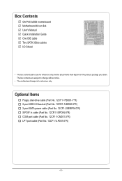
.... 12CF1-2SERPW-0*R) S/PDIF In cable (Part No. 12CR1-1SPDIN-0*R) COM port cable (Part No. 12CF1-1CM001-3*R) LPT port cable (Part No. 12CF1-1LP001-0*R) - 6 - Box Contents GA-P55-USB3 motherboard Motherboard driver disk User's Manual Quick Installation Guide One IDE cable Two SATA 3Gb/s cables I/O Shield • The box contents above are subject to...
.... 12CF1-2SERPW-0*R) S/PDIF In cable (Part No. 12CR1-1SPDIN-0*R) COM port cable (Part No. 12CF1-1CM001-3*R) LPT port cable (Part No. 12CF1-1LP001-0*R) - 6 - Box Contents GA-P55-USB3 motherboard Motherboard driver disk User's Manual Quick Installation Guide One IDE cable Two SATA 3Gb/s cables I/O Shield • The box contents above are subject to...

Manual
Page 7
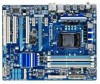
... R_SPDIF CPU_FAN ATX_12V_2X4 R_USB_2 R_USB_1 R_USB30 LGA1156 PWR_FAN PHASE LED ATX USB_LAN NEC AUDIO F_AUDIO RTL8111D PCIEX16 GA-P55-USB3 PCIEX1_1 (Note) SYS_FAN1 IDE SYS_FAN2 DDR3_2 DDR3_1 DDR3_4 DDR3_3 PCIEX1_2 BAT CODEC PCI1 PCIEX4_X1 GIGABYTE SATA2 Intel® P55/H55 GSATA2_6 GSATA2_7 CD_IN SPDIF_I SPDIF_O IT8720 PCI2 PCI3 LPT COMA B_BIOS FDD F_USB2 M_BIOS CLR_CMOS...
... R_SPDIF CPU_FAN ATX_12V_2X4 R_USB_2 R_USB_1 R_USB30 LGA1156 PWR_FAN PHASE LED ATX USB_LAN NEC AUDIO F_AUDIO RTL8111D PCIEX16 GA-P55-USB3 PCIEX1_1 (Note) SYS_FAN1 IDE SYS_FAN2 DDR3_2 DDR3_1 DDR3_4 DDR3_3 PCIEX1_2 BAT CODEC PCI1 PCIEX4_X1 GIGABYTE SATA2 Intel® P55/H55 GSATA2_6 GSATA2_7 CD_IN SPDIF_I SPDIF_O IT8720 PCI2 PCI3 LPT COMA B_BIOS FDD F_USB2 M_BIOS CLR_CMOS...

Manual
Page 8
.... j Only for H55 Chipset. GA-P55-USB3 Motherboard Block Diagram PCIe CLK (100 MHz) 1 PCI Express x16 LGA1156 CPU CPU CLK+/- (133 MHz) DDR3 2200/1333/1066/800 MHz Dual Channel Memory ... Express x1 (PCIEX1_2) 2 USB 3.0 x1 x4j/X1k Switchj NEC PCI Express Bus Dual BIOS Intel® P55/H55 6 SATA 3Gb/s x1 14 USB 2.0/1.1j (Note) 2 SATA 3Gb/s ATA-133/100/66/33 IDE Channel GIGABYTE SATA2 12 USB 2.0/1.1k (Note) PCI Bus LPC Bus Floppy CODEC IT8720 COM Port PS/2 KB/Mouse...
.... j Only for H55 Chipset. GA-P55-USB3 Motherboard Block Diagram PCIe CLK (100 MHz) 1 PCI Express x16 LGA1156 CPU CPU CLK+/- (133 MHz) DDR3 2200/1333/1066/800 MHz Dual Channel Memory ... Express x1 (PCIEX1_2) 2 USB 3.0 x1 x4j/X1k Switchj NEC PCI Express Bus Dual BIOS Intel® P55/H55 6 SATA 3Gb/s x1 14 USB 2.0/1.1j (Note) 2 SATA 3Gb/s ATA-133/100/66/33 IDE Channel GIGABYTE SATA2 12 USB 2.0/1.1k (Note) PCI Bus LPC Bus Floppy CODEC IT8720 COM Port PS/2 KB/Mouse...

Manual
Page 10
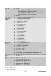
...® Core™ i5 series processor in the LGA1156 package (Go to GIGABYTE's website for the latest CPU support list.) L3 cache varies with CPU Chipset Intel® P55/H55 Express Chipset Memory Audio 4 x 1.5V DDR3 DIMM sockets supporting...; 2 x PCI Express x1 slots 3 x PCI slots Multi-Graphics Support for SATA RAID 0, RAID 1, RAID 5, and RAID 10 j GIGABYTE SATA2 chip: - 1 x IDE connector supporting ATA-133/100/66/33 and up to 2 IDE devices - 2 x SATA 3Gb/s connectors (GSATA2_6, GSATA2_7) supporting up...
...® Core™ i5 series processor in the LGA1156 package (Go to GIGABYTE's website for the latest CPU support list.) L3 cache varies with CPU Chipset Intel® P55/H55 Express Chipset Memory Audio 4 x 1.5V DDR3 DIMM sockets supporting...; 2 x PCI Express x1 slots 3 x PCI slots Multi-Graphics Support for SATA RAID 0, RAID 1, RAID 5, and RAID 10 j GIGABYTE SATA2 chip: - 1 x IDE connector supporting ATA-133/100/66/33 and up to 2 IDE devices - 2 x SATA 3Gb/s connectors (GSATA2_6, GSATA2_7) supporting up...
Manual
Page 11
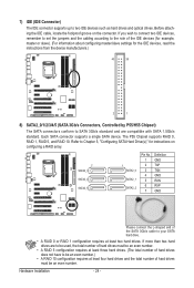
USB Chipset: - k Only for P55 Chipset. Hardware Installation Up to 14 USB 2.0/1.1 ports (Note 5) (10 on the back panel, 4 via the USB brackets connected to 2 USB 3.0 ports on the back ...
USB Chipset: - k Only for P55 Chipset. Hardware Installation Up to 14 USB 2.0/1.1 ports (Note 5) (10 on the back panel, 4 via the USB brackets connected to 2 USB 3.0 ports on the back ...
Manual
Page 12
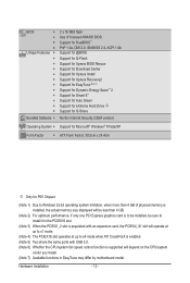
... Internet Security (OEM version) Operating System w Support for Microsoft® Windows® 7/Vista/XP Form Factor w ATX Form Factor; 30.5cm x 24.4cm j Only for P55 Chipset. (Note 1) Due to Windows 32-bit operating system limitation, when more than 4 GB of physical memory is installed, the actual memory size displayed will...
... Internet Security (OEM version) Operating System w Support for Microsoft® Windows® 7/Vista/XP Form Factor w ATX Form Factor; 30.5cm x 24.4cm j Only for P55 Chipset. (Note 1) Due to Windows 32-bit operating system limitation, when more than 4 GB of physical memory is installed, the actual memory size displayed will...
Manual
Page 19
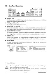
... LAN port LEDs. PS/2 Keyboard/Mouse Port Use this feature, ensure that your audio system provides a coaxial digital audio in connector. Use this port for P55 Chipset. • When removing the cable connected to a back panel connector, first remove the cable from the motherboard. • When removing the cable, pull it...
... LAN port LEDs. PS/2 Keyboard/Mouse Port Use this feature, ensure that your audio system provides a coaxial digital audio in connector. Use this port for P55 Chipset. • When removing the cable connected to a back panel connector, first remove the cable from the motherboard. • When removing the cable, pull it...
Manual
Page 24
... to Chapter 5, "Configuring SATA Hard Drive(s)," for the IDE devices, read the instructions from the device manufacturers.) 40 39 2 1 8) SATA2_0/1/2/3/4/5 (SATA 3Gb/s Connectors, Controlled by P55/H55 Chipset) The SATA connectors conform to SATA 3Gb/s standard and are to be an even number. Each SATA connector supports a single SATA device. The...
... to Chapter 5, "Configuring SATA Hard Drive(s)," for the IDE devices, read the instructions from the device manufacturers.) 40 39 2 1 8) SATA2_0/1/2/3/4/5 (SATA 3Gb/s Connectors, Controlled by P55/H55 Chipset) The SATA connectors conform to SATA 3Gb/s standard and are to be an even number. Each SATA connector supports a single SATA device. The...
Manual
Page 34
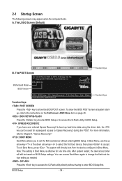
... the first boot device without having to Xpress Recovery2 during the POST. The LOGO Screen (Default) B. Motherboard Model BIOS Version P55-USB3 D4 . . . . : BIOS Setup : XpressRecovery2 : Boot Menu : Qflash 12/04/2009-P55-7A89TG0DC-00 Function Keys Function Keys Function Keys: : POST SCREEN Press the key to show the BIOS POST screen at...
... the first boot device without having to Xpress Recovery2 during the POST. The LOGO Screen (Default) B. Motherboard Model BIOS Version P55-USB3 D4 . . . . : BIOS Setup : XpressRecovery2 : Boot Menu : Qflash 12/04/2009-P55-7A89TG0DC-00 Function Keys Function Keys Function Keys: : POST SCREEN Press the key to show the BIOS POST screen at...
Manual
Page 50
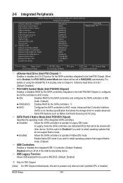
...in Legacy IDE mode. Disabled Allows the SATA controllers to operate in the Intel P55/H55 Chipset or configures the SATA controllers to AHCI mode. BIOS Setup - 50 - For details on using the GIGABYTE X.H.D utility, refer to Chaper 4, "eXtreme Hard Drive (X.H.D)." (Default: Disabled) ...PCH SATA Control Mode (Intel P55/H55 Chipset) Enables or disables RAID for the SATA controllers integrated in Native IDE mode....
...in Legacy IDE mode. Disabled Allows the SATA controllers to operate in the Intel P55/H55 Chipset or configures the SATA controllers to AHCI mode. BIOS Setup - 50 - For details on using the GIGABYTE X.H.D utility, refer to Chaper 4, "eXtreme Hard Drive (X.H.D)." (Default: Disabled) ...PCH SATA Control Mode (Intel P55/H55 Chipset) Enables or disables RAID for the SATA controllers integrated in Native IDE mode....
Manual
Page 68
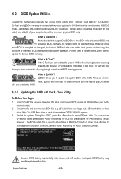
...take over on the main BIOS. GIGABYTE Q-Flash and @BIOS are easy-to ensure normal system operation. What is potentially risky, please do it with the Q-Flash Utility A. P55-USB3 D4 . . . . : BIOS Setup : XpressRecovery2 : Boot Menu : Qflash 12/04/2009-P55-7A89TG0DC-00 Because BIOS flashing is...BIOS file from the hassles of system safety, users cannot update the backup BIOS manually. Embedded in system malfunction. 4-2 BIOS Update Utilities GIGABYTE motherboards provide two unique BIOS update tools, Q-Flash™ and @BIOS™. Restart the system. With Q-Flash you to enter ...
...take over on the main BIOS. GIGABYTE Q-Flash and @BIOS are easy-to ensure normal system operation. What is potentially risky, please do it with the Q-Flash Utility A. P55-USB3 D4 . . . . : BIOS Setup : XpressRecovery2 : Boot Menu : Qflash 12/04/2009-P55-7A89TG0DC-00 Because BIOS flashing is...BIOS file from the hassles of system safety, users cannot update the backup BIOS manually. Embedded in system malfunction. 4-2 BIOS Update Utilities GIGABYTE motherboards provide two unique BIOS update tools, Q-Flash™ and @BIOS™. Restart the system. With Q-Flash you to enter ...

Manual
Page 80
... and quickly set up a RAID-ready system and configure it for RAID 0. Exits the X.H.D utility: Click Cancel to enable RAID for P55 Chipset. (Note 1) The X.H.D utility only supports the SATA controllers integrated in the Intel Chipset. (Note 2) It is greater than the...Setting Up a RAID-Ready System Step 1: Configure the system BIOS Enter the system BIOS Setup program, set up a RAID 0 array. 2. A. Using GIGABYTE eXtreme Hard Drive (X.H.D) Instructions:(Note 2) Before launching X.H.D, make sure the new drive is recommended that already exists, users also can go to the Application...
... and quickly set up a RAID-ready system and configure it for RAID 0. Exits the X.H.D utility: Click Cancel to enable RAID for P55 Chipset. (Note 1) The X.H.D utility only supports the SATA controllers integrated in the Intel Chipset. (Note 2) It is greater than the...Setting Up a RAID-Ready System Step 1: Configure the system BIOS Enter the system BIOS Setup program, set up a RAID 0 array. 2. A. Using GIGABYTE eXtreme Hard Drive (X.H.D) Instructions:(Note 2) Before launching X.H.D, make sure the new drive is recommended that already exists, users also can go to the Application...
Manual
Page 81
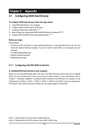
... drive and the other end to the hard drive. (Note 1) Skip this motherboard, the SATA2_0, SATA2_1, SATA2_2, SATA2_3, SATA2_4 and SATA2_5 ports are supported by P55 Chipset.) Then connect the power connector from your computer. Appendix B. Configure SATA controller mode in RAID BIOS. (Note 1) D. If there is set to identify the... on your computer Attach one hard drive. • An empty formatted floppy disk. • Windows Vista/XP setup disk. • Motherboard driver disk. 5-1-1 Configuring Intel P55 SATA Controllers A.
... drive and the other end to the hard drive. (Note 1) Skip this motherboard, the SATA2_0, SATA2_1, SATA2_2, SATA2_3, SATA2_4 and SATA2_5 ports are supported by P55 Chipset.) Then connect the power connector from your computer. Appendix B. Configure SATA controller mode in RAID BIOS. (Note 1) D. If there is set to identify the... on your computer Attach one hard drive. • An empty formatted floppy disk. • Windows Vista/XP setup disk. • Motherboard driver disk. 5-1-1 Configuring Intel P55 SATA Controllers A.
Manual
Page 83
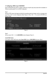
... 4. All Rights Reserved. All Rights Reserved. [ MAIN MENU ] 1. Appendix Configuring a RAID array in MAIN MENU and press . Figure 2 Step 2: After you want to enter the P55 RAID Configuration Utility. Intel(R) Rapid Storage Technology - Create RAID Volume 2. Reset Disks to configure a RAID array. option ROM - 9.5.0.1037 Copyright(C) 2003-09 Intel Corporation. Physical...
... 4. All Rights Reserved. All Rights Reserved. [ MAIN MENU ] 1. Appendix Configuring a RAID array in MAIN MENU and press . Figure 2 Step 2: After you want to enter the P55 RAID Configuration Utility. Intel(R) Rapid Storage Technology - Create RAID Volume 2. Reset Disks to configure a RAID array. option ROM - 9.5.0.1037 Copyright(C) 2003-09 Intel Corporation. Physical...
Manual
Page 95
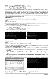
... driver in MS-DOS and Windows mode. Depending on the operating system to a floppy disk. tem. • For the GIGABYTE SATA2, select 3) GIGABYTE GSATA driver for 32bit system for Windows 32-bit operating system. Press after the command: • For the Intel... P55, type (Figure 1): (Note) A:\>copy d:\bootdrv\irst\32bit\*.* • For the GIGABYTE SATA2, type (Figure 2): (Note) A:\>copy d:\bootdrv\gsata\32bit\*.* Figure 1 Figure 2 In Windows mode: Steps: 1: Use ...
... driver in MS-DOS and Windows mode. Depending on the operating system to a floppy disk. tem. • For the GIGABYTE SATA2, select 3) GIGABYTE GSATA driver for 32bit system for Windows 32-bit operating system. Press after the command: • For the Intel... P55, type (Figure 1): (Note) A:\>copy d:\bootdrv\irst\32bit\*.* • For the GIGABYTE SATA2, type (Figure 2): (Note) A:\>copy d:\bootdrv\gsata\32bit\*.* Figure 1 Figure 2 In Windows mode: Steps: 1: Use ...
Manual
Page 96
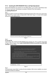
... driver diskette and correct BIOS settings, you can proceed with Windows, using a device support disk provided by an adapter manufacturer. A. Figure 1 Step 2: For the Intel P55: Insert the floppy disk containing the SATA RAID/AHCI driver and press .
... driver diskette and correct BIOS settings, you can proceed with Windows, using a device support disk provided by an adapter manufacturer. A. Figure 1 Step 2: For the Intel P55: Insert the floppy disk containing the SATA RAID/AHCI driver and press .
