Manual
Page 3
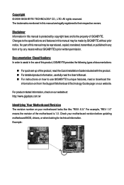
... product-related information, check on our website at: http://www.gigabyte.com.tw Identifying Your Motherboard Revision The revision number on your motherboard revision before updating motherboard BIOS, drivers, or when looking for technical information. Changes to the specifications and features in ... the information on/from the Support\Motherboard\Technology Guide page on how to assist in this manual may be made by GIGABYTE without GIGABYTE's prior written permission. Documentation Classifications In order to use of the product, read the Quick Installation Guide included with the...
... product-related information, check on our website at: http://www.gigabyte.com.tw Identifying Your Motherboard Revision The revision number on your motherboard revision before updating motherboard BIOS, drivers, or when looking for technical information. Changes to the specifications and features in ... the information on/from the Support\Motherboard\Technology Guide page on how to assist in this manual may be made by GIGABYTE without GIGABYTE's prior written permission. Documentation Classifications In order to use of the product, read the Quick Installation Guide included with the...
Manual
Page 4
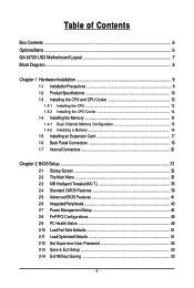
Table of Contents Box Contents ...6 OptionalItems...6 GA-M720-US3 Motherboard Layout 7 Block Diagram...8 Chapter 1 Hardware Installation 9 1-1 Installation Precautions 9 1-2 Product Specifications 10 1-3 Installing the CPU and CPU Cooler ... Installing an Expansion Card 17 1-6 Back Panel Connectors 18 1-7 Internal Connectors 20 Chapter 2 BIOS Setup 31 2-1 Startup Screen 32 2-2 The Main Menu 33 2-3 MB Intelligent Tweaker(M.I.T 35 2-4 Standard CMOS Features 39 2-5 Advanced BIOS Features 41 2-6 IntegratedPeripherals 43 2-7 Power Management Setup 46 2-8 PnP/PCI Configurations 48 2-9 ...
Table of Contents Box Contents ...6 OptionalItems...6 GA-M720-US3 Motherboard Layout 7 Block Diagram...8 Chapter 1 Hardware Installation 9 1-1 Installation Precautions 9 1-2 Product Specifications 10 1-3 Installing the CPU and CPU Cooler ... Installing an Expansion Card 17 1-6 Back Panel Connectors 18 1-7 Internal Connectors 20 Chapter 2 BIOS Setup 31 2-1 Startup Screen 32 2-2 The Main Menu 33 2-3 MB Intelligent Tweaker(M.I.T 35 2-4 Standard CMOS Features 39 2-5 Advanced BIOS Features 41 2-6 IntegratedPeripherals 43 2-7 Power Management Setup 46 2-8 PnP/PCI Configurations 48 2-9 ...
Manual
Page 5
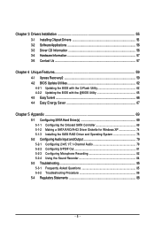
... 56 3-3 Driver CD Information 56 3-4 Hardware Information 57 3-5 Contact Us ...57 Chapter 4 Unique Features 59 4-1 Xpress Recovery2 59 4-2 BIOS Update Utilities 62 4-2-1 Updating the BIOS with the Q-Flash Utility 62 4-2-2 Updating the BIOS with the @BIOS Utility 65 4-3 EasyTune 6 ...66 4-4 Easy Energy Saver 67 Chapter 5 Appendix ...69 5-1 Configuring SATA Hard Drive(s 69 5-1-1 Configuring the...
... 56 3-3 Driver CD Information 56 3-4 Hardware Information 57 3-5 Contact Us ...57 Chapter 4 Unique Features 59 4-1 Xpress Recovery2 59 4-2 BIOS Update Utilities 62 4-2-1 Updating the BIOS with the Q-Flash Utility 62 4-2-2 Updating the BIOS with the @BIOS Utility 65 4-3 EasyTune 6 ...66 4-4 Easy Energy Saver 67 Chapter 5 Appendix ...69 5-1 Configuring SATA Hard Drive(s 69 5-1-1 Configuring the...
Manual
Page 8
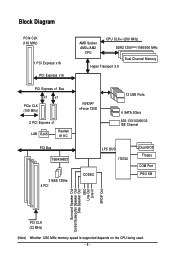
... TSB43AB23 3 IEEE 1394a 4 PCI NVIDIA® nForce 720D 12 USB Ports 6 SATA 3Gb/s ATA-133/100/66/33 IDE Channel LPC BUS IT8720 CODEC Dual BIOS Floppy COM Port PS/2 KB Surround Speaker Out Center/Subwoofer Speaker Out Side Speaker Out MIC Line-Out Line-In SPDIF Out PCI CLK (33...
... TSB43AB23 3 IEEE 1394a 4 PCI NVIDIA® nForce 720D 12 USB Ports 6 SATA 3Gb/s ATA-133/100/66/33 IDE Channel LPC BUS IT8720 CODEC Dual BIOS Floppy COM Port PS/2 KB Surround Speaker Out Center/Subwoofer Speaker Out Side Speaker Out MIC Line-Out Line-In SPDIF Out PCI CLK (33...
Manual
Page 11
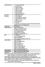
... CPU/System fan speed control (Note 3) BIOS 2 x 8 Mbit flash Use of licensed AWARD BIOS Support for DualBIOSTM PnP 1.0a, DMI 2.0, SM BIOS 2.4, ACPI 1.0b Unique Features Support for @BIOS Support for Download Center Support...; Support for EasyTune (Note 4) Support for Xpress Install Support for Xpress Recovery2 Support for Virtual Dual BIOS Support for Easy Energy Saver (Note 5) Bundled Software Norton Internet Security (OEM version) Operating System Support...
... CPU/System fan speed control (Note 3) BIOS 2 x 8 Mbit flash Use of licensed AWARD BIOS Support for DualBIOSTM PnP 1.0a, DMI 2.0, SM BIOS 2.4, ACPI 1.0b Unique Features Support for @BIOS Support for Download Center Support...; Support for EasyTune (Note 4) Support for Xpress Install Support for Xpress Recovery2 Support for Virtual Dual BIOS Support for Easy Energy Saver (Note 5) Bundled Software Norton Internet Security (OEM version) Operating System Support...
Manual
Page 15
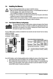
...unplug the power cord from the power outlet before installing the memory in Dual Channel mode. 1. Dual Channel mode cannot be used . (Go to GIGABYTE's website for optimum performance. - 15 - The four DDR2 memory sockets are unable to prevent hardware damage. • Memory modules have a foolproof ... be enabled if only one direction. A memory module can be used and installed in only one DDR2 memory module is installed, the BIOS will double the original memory bandwidth. When enabling Dual Channel mode with two or four memory modules, it is recommended that the motherboard ...
...unplug the power cord from the power outlet before installing the memory in Dual Channel mode. 1. Dual Channel mode cannot be used . (Go to GIGABYTE's website for optimum performance. - 15 - The four DDR2 memory sockets are unable to prevent hardware damage. • Memory modules have a foolproof ... be enabled if only one direction. A memory module can be used and installed in only one DDR2 memory module is installed, the BIOS will double the original memory bandwidth. When enabling Dual Channel mode with two or four memory modules, it is recommended that the motherboard ...
Manual
Page 17
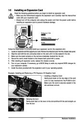
...an Expansion Card Read the following guidelines before installing an expansion card to the chassis back panel with a screw. 5. If necessary, go to BIOS Setup to install an expansion card: • Make sure the motherboard supports the expansion card. Example: Installing and Removing a PCI Express x16...cord from the chassis back panel. 2. Remove the metal slot cover from the power outlet before you begin to make any required BIOS changes for your card. Hardware Installation Make sure the card is fully inserted into the slot. 4. Carefully read the manual that ...
...an Expansion Card Read the following guidelines before installing an expansion card to the chassis back panel with a screw. 5. If necessary, go to BIOS Setup to install an expansion card: • Make sure the motherboard supports the expansion card. Example: Installing and Removing a PCI Express x16...cord from the chassis back panel. 2. Remove the metal slot cover from the power outlet before you begin to make any required BIOS changes for your card. Hardware Installation Make sure the card is fully inserted into the slot. 4. Carefully read the manual that ...
Manual
Page 24
... of the positive side (+) and the negative side (-) of the battery holder, making them short for 5 seconds.) 3. Plug in S1 sleep state. GA-M720-US3 Motherboard - 24 - Turn off your computer and unplug the power cord before replacing the battery. • Replace the battery with an equivalent one minute.... (Or use a metal object like a screwdriver to keep the values (such as BIOS configurations, date, and time information) in the CMOS when the computer is in the power cord and restart your computer. • Always turn ...
... of the positive side (+) and the negative side (-) of the battery holder, making them short for 5 seconds.) 3. Plug in S1 sleep state. GA-M720-US3 Motherboard - 24 - Turn off your computer and unplug the power cord before replacing the battery. • Replace the battery with an equivalent one minute.... (Or use a metal object like a screwdriver to keep the values (such as BIOS configurations, date, and time information) in the CMOS when the computer is in the power cord and restart your computer. • Always turn ...

Manual
Page 25
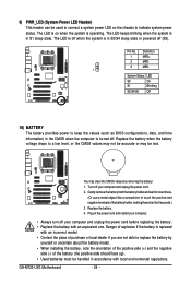
... Blinking the system is in S3/S4/S5 Off S3/S4 sleep state or powered off your system using the power switch (refer to Chapter 2, "BIOS Setup," "Power Management Setup," for information about beep codes. • HD (Hard Drive Activity LED, Blue) Connects to the reset switch on when... the hard drive is detected, the BIOS may issue beeps in S1 sleep state. The system reports system startup status by chassis. RESRES+ NC Hard Drive Activity LED Reset Switch • MSG...
... Blinking the system is in S3/S4/S5 Off S3/S4 sleep state or powered off your system using the power switch (refer to Chapter 2, "BIOS Setup," "Power Management Setup," for information about beep codes. • HD (Hard Drive Activity LED, Blue) Connects to the reset switch on when... the hard drive is detected, the BIOS may issue beeps in S1 sleep state. The system reports system startup status by chassis. RESRES+ NC Hard Drive Activity LED Reset Switch • MSG...
Manual
Page 29
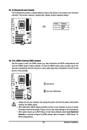
...the two pins or use a metal object like a screwdriver to Chapter 2, "BIOS Setup," for a few seconds. Pin No. This function requires a chassis with chassis intrusion detection design. date information and BIOS configurations) and reset the CMOS values to clear the CMOS values (e.g. Failure ...to do so may cause damage to the motherboard. • After system restart, go to BIOS Setup to load factory defaults (select Load Optimized...
...the two pins or use a metal object like a screwdriver to Chapter 2, "BIOS Setup," for a few seconds. Pin No. This function requires a chassis with chassis intrusion detection design. date information and BIOS configurations) and reset the CMOS values to clear the CMOS values (e.g. Failure ...to do so may cause damage to the motherboard. • After system restart, go to BIOS Setup to load factory defaults (select Load Optimized...

Manual
Page 31
...to default values. (Refer to activate certain system features. Chapter 2 BIOS Setup BIOS (Basic Input and Output System) records hardware parameters of the BIOS Setup program. To upgrade the BIOS, use either the GIGABYTE Q-Flash or @BIOS utility. • Q-Flash allows the user to quickly and easily... upgrade or back up BIOS without entering the operating system. • @BIOS is a Windows-based utility that...
...to default values. (Refer to activate certain system features. Chapter 2 BIOS Setup BIOS (Basic Input and Output System) records hardware parameters of the BIOS Setup program. To upgrade the BIOS, use either the GIGABYTE Q-Flash or @BIOS utility. • Q-Flash allows the user to quickly and easily... upgrade or back up BIOS without entering the operating system. • @BIOS is a Windows-based utility that...
Manual
Page 32
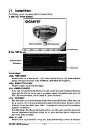
... device, then press to access the Q-Flash utility directly without entering BIOS Setup. Note: The setting in Boot Menu. To exit Boot Menu, press . The system will still be used for one time only. GA-M720-US3 Motherboard - 32 - In Boot Menu, use the up hard drive... will directly boot from the device configured in Boot Menu is effective for subsequent access to show the BIOS POST screen at system startup, refer to enter BIOS Setup first. M720-US3 F1ec . . . . : BIOS Setup : XpressRecovery2 : Boot Menu : Qflash 12/26/2008-NF-MCP78-6A610G06C-00 Function Keys Function ...
... device, then press to access the Q-Flash utility directly without entering BIOS Setup. Note: The setting in Boot Menu. To exit Boot Menu, press . The system will still be used for one time only. GA-M720-US3 Motherboard - 32 - In Boot Menu, use the up hard drive... will directly boot from the device configured in Boot Menu is effective for subsequent access to show the BIOS POST screen at system startup, refer to enter BIOS Setup first. M720-US3 F1ec . . . . : BIOS Setup : XpressRecovery2 : Boot Menu : Qflash 12/26/2008-NF-MCP78-6A610G06C-00 Function Keys Function ...

Manual
Page 33
... item is in the Item Help block on the right side of the submenu. • If you do not find the settings you enter the BIOS Setup program, the Main Menu (as usual, select the Load Optimized Defaults item to set your system to access more advanced options. • When ... Password Save & Exit Setup Exit Without Saving ESC: Quit F8: Q-Flash Select Item F10: Save & Exit Setup F11: Save CMOS to BIOS F12: Load CMOS from BIOS Change CPU's Clock & Voltage BIOS Setup Program Function Keys Move the selection bar to select an item Execute command or enter the submenu Main Menu: Exit...
... item is in the Item Help block on the right side of the submenu. • If you do not find the settings you enter the BIOS Setup program, the Main Menu (as usual, select the Load Optimized Defaults item to set your system to access more advanced options. • When ... Password Save & Exit Setup Exit Without Saving ESC: Quit F8: Q-Flash Select Item F10: Save & Exit Setup F11: Save CMOS to BIOS F12: Load CMOS from BIOS Change CPU's Clock & Voltage BIOS Setup Program Function Keys Move the selection bar to select an item Execute command or enter the submenu Main Menu: Exit...
Manual
Page 34
... voltages of your CPU, memory, etc. Standard CMOS Features Use this task.) GA-M720-US3 Motherboard - 34 - You can also carry out this function to load the BIOS settings from BIOS If your system becomes unstable and you have loaded the BIOS default settings, you can also carry out this menu to configure the system...
... voltages of your CPU, memory, etc. Standard CMOS Features Use this task.) GA-M720-US3 Motherboard - 34 - You can also carry out this function to load the BIOS settings from BIOS If your system becomes unstable and you have loaded the BIOS default settings, you can also carry out this menu to configure the system...
Manual
Page 35
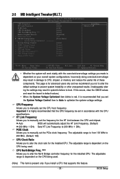
... the CPU frequency be set in red, it is dependent on the CPU being used . Important It is dependent on your overall system configurations. BIOS Setup Auto BIOS will work stably with the CPU specifications. PCIE Clock Allows you made is highly recommended that you not to alter the default settings to...
... the CPU frequency be set in red, it is dependent on the CPU being used . Important It is dependent on your overall system configurations. BIOS Setup Auto BIOS will work stably with the CPU specifications. PCIE Clock Allows you made is highly recommended that you not to alter the default settings to...
Manual
Page 36
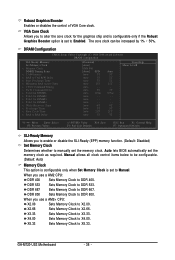
...disable the SLI-Ready (EPP) memory function. (Default: Disabled) Set Memory Clock Determines whether to Enabled. DDR 800 Sets Memory Clock to DDR 533. GA-M720-US3 Motherboard - 36 - The core clock can be configurable. (Default: Auto) Memory Clock This option is configurable only when Set Memory Clock is set ...When you to alter the core clock for DIMM4 x Write Recovery Time x Precharge Time x Row Cycle Time x RAS to X3.33. Auto lets BIOS automatically set the memory clock. X4.00 Sets Memory Clock to X5.33. X5.33 Sets Memory Clock to X4.00. Auto 3T Auto 105ns...
...disable the SLI-Ready (EPP) memory function. (Default: Disabled) Set Memory Clock Determines whether to Enabled. DDR 800 Sets Memory Clock to DDR 533. GA-M720-US3 Motherboard - 36 - The core clock can be configurable. (Default: Auto) Memory Clock This option is configurable only when Set Memory Clock is set ...When you to alter the core clock for DIMM4 x Write Recovery Time x Precharge Time x Row Cycle Time x RAS to X3.33. Auto lets BIOS automatically set the memory clock. X4.00 Sets Memory Clock to X5.33. X5.33 Sets Memory Clock to X4.00. Auto 3T Auto 105ns...
Manual
Page 37
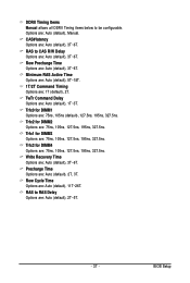
... (default), 3T~6T. Trfc0 for DIMM4 Options are : 75ns, 105ns (default), 127.5ns, 195ns, 327.5ns. Precharge Time Options are : Auto (default), 2T~5T. - 37 - BIOS Setup Trfc3 for DIMM1 Options are : 75ns, 105ns, 127.5ns, 195ns, 327.5ns. RAS to be configurable. CAS# latency Options are : 1T (default), 2T. Minimum...
... (default), 3T~6T. Trfc0 for DIMM4 Options are : 75ns, 105ns (default), 127.5ns, 195ns, 327.5ns. Precharge Time Options are : Auto (default), 2T~5T. - 37 - BIOS Setup Trfc3 for DIMM1 Options are : 75ns, 105ns, 127.5ns, 195ns, 327.5ns. RAS to be configurable. CAS# latency Options are : 1T (default), 2T. Minimum...
Manual
Page 38
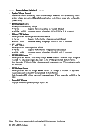
... whether to manually set the voltage of the PCI Express bus. Chipset/PCIE Voltage Allows you install a CPU that supports this feature. Auto lets BIOS automatically set the system voltages as required. Normal Supplies the Northbridge voltage as required. (Default) +0.1V ~ +0.2V Increases memory voltage by 0.1V...) Note: Increasing CPU North Bridge voltage may result in damage to 0.30V at 0.1V increment. Normal Supplies the memory voltage as required. GA-M720-US3 Motherboard - 38 - The adjustable range is present only if you to set the system voltages.
... whether to manually set the voltage of the PCI Express bus. Chipset/PCIE Voltage Allows you install a CPU that supports this feature. Auto lets BIOS automatically set the system voltages as required. Normal Supplies the Northbridge voltage as required. (Default) +0.1V ~ +0.2V Increases memory voltage by 0.1V...) Note: Increasing CPU North Bridge voltage may result in damage to 0.30V at 0.1V increment. Normal Supplies the memory voltage as required. GA-M720-US3 Motherboard - 38 - The adjustable range is present only if you to set the system voltages.
Manual
Page 39
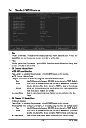
...access mode. Extended IDE Drive Configure your IDE/SATA devices by using one of the two methods below : • Auto • None Lets BIOS automatically detect IDE/SATA devices during the POST. (Default) If no IDE/SATA devices are used , set to autodetect the parameters of the ... 2, 3 Master/Slave IDE Auto-Detection Press to None so the system will skip the detection of the device during the POST for faster system startup. BIOS Setup Time Sets the system time. For example, 1 p.m. is week (read-only), month, date and year. 2-4 Standard CMOS Features Date (mm:dd:...
...access mode. Extended IDE Drive Configure your IDE/SATA devices by using one of the two methods below : • Auto • None Lets BIOS automatically detect IDE/SATA devices during the POST. (Default) If no IDE/SATA devices are used , set to autodetect the parameters of the ... 2, 3 Master/Slave IDE Auto-Detection Press to None so the system will skip the detection of the device during the POST for faster system startup. BIOS Setup Time Sets the system time. For example, 1 p.m. is week (read-only), month, date and year. 2-4 Standard CMOS Features Date (mm:dd:...
Manual
Page 40
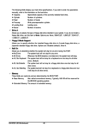
..., But Diskette The system boot will not stop for a floppy disk drive error but it will stop for the MS-DOS operating system. GA-M720-US3 Motherboard - 40 - If you wish to enter the parameters manually, refer to selects the type of extended memory. Head Number of the currently...the installed floppy disk drive is 3-mode floppy disk drive, a Japanese standard floppy disk drive. Options are determined by the BIOS POST. All Errors Whenever the BIOS detects a non-fatal error the system boot will be reserved for all other errors. Cylinder Number of sectors. Precomp Write ...
..., But Diskette The system boot will not stop for a floppy disk drive error but it will stop for the MS-DOS operating system. GA-M720-US3 Motherboard - 40 - If you wish to enter the parameters manually, refer to selects the type of extended memory. Head Number of the currently...the installed floppy disk drive is 3-mode floppy disk drive, a Japanese standard floppy disk drive. Options are determined by the BIOS POST. All Errors Whenever the BIOS detects a non-fatal error the system boot will be reserved for all other errors. Cylinder Number of sectors. Precomp Write ...


