Manual
Page 1
GA-M720-US3 AM2+/AM2 socket motherboard for AMD PhenomTM FX processor/AMD PhenomTM X4 processor/ AMD PhenomTM X3 processor/AMD AthlonTM X2 processor/ AMD AthlonTM processor/AMD SempronTM X2 processor/ AMD SempronTM processor User's Manual Rev. 1002 12ME-M720US3-1002R
GA-M720-US3 AM2+/AM2 socket motherboard for AMD PhenomTM FX processor/AMD PhenomTM X4 processor/ AMD PhenomTM X3 processor/AMD AthlonTM X2 processor/ AMD AthlonTM processor/AMD SempronTM X2 processor/ AMD SempronTM processor User's Manual Rev. 1002 12ME-M720US3-1002R
Manual
Page 2
Motherboard GA-M720-US3 Dec. 8, 2008 Motherboard GA-M720-US3 Dec. 8, 2008
Motherboard GA-M720-US3 Dec. 8, 2008 Motherboard GA-M720-US3 Dec. 8, 2008
Manual
Page 3
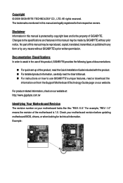
...the product. For detailed product information, carefully read the User's Manual. For instructions on how to use GIGABYTE's unique features, read or download the information on/from the Support\Motherboard\Technology Guide page on your motherboard revision before updating ...looking for technical information. Changes to their respective owners. For product-related information, check on our website at: http://www.gigabyte.com.tw Identifying Your Motherboard Revision The revision number on our website. Example: Documentation Classifications In order to assist in ...
...the product. For detailed product information, carefully read the User's Manual. For instructions on how to use GIGABYTE's unique features, read or download the information on/from the Support\Motherboard\Technology Guide page on your motherboard revision before updating ...looking for technical information. Changes to their respective owners. For product-related information, check on our website at: http://www.gigabyte.com.tw Identifying Your Motherboard Revision The revision number on our website. Example: Documentation Classifications In order to assist in ...
Manual
Page 4
Table of Contents Box Contents ...6 OptionalItems...6 GA-M720-US3 Motherboard Layout 7 Block Diagram...8 Chapter 1 Hardware Installation 9 1-1 Installation Precautions 9 1-2 Product Specifications 10 1-3 Installing the CPU and CPU Cooler 12 1-3-1 Installing the CPU 12 1-3-2 Installing the ...
Table of Contents Box Contents ...6 OptionalItems...6 GA-M720-US3 Motherboard Layout 7 Block Diagram...8 Chapter 1 Hardware Installation 9 1-1 Installation Precautions 9 1-2 Product Specifications 10 1-3 Installing the CPU and CPU Cooler 12 1-3-1 Installing the CPU 12 1-3-2 Installing the ...
Manual
Page 5
Chapter 3 Drivers Installation 55 3-1 Installing Chipset Drivers 55 3-2 Software Applications 56 3-3 Driver CD Information 56 3-4 Hardware Information 57 3-5 Contact Us ...57 Chapter 4 Unique Features 59 4-1 Xpress Recovery2 59 4-2 BIOS Update Utilities 62 4-2-1 Updating the BIOS with the Q-Flash Utility 62 4-2-2 Updating the BIOS with the @BIOS Utility 65 4-3 EasyTune 6 ...66 4-4 Easy Energy Saver 67 Chapter 5 Appendix ...69 5-1 Configuring SATA Hard Drive(s 69 5-1-1 Configuring the Onboard SATA Controller 69 5-1-2 Making a SATA RAID/AHCI Driver Diskette for Windows XP 74 5-1-3 ...
Chapter 3 Drivers Installation 55 3-1 Installing Chipset Drivers 55 3-2 Software Applications 56 3-3 Driver CD Information 56 3-4 Hardware Information 57 3-5 Contact Us ...57 Chapter 4 Unique Features 59 4-1 Xpress Recovery2 59 4-2 BIOS Update Utilities 62 4-2-1 Updating the BIOS with the Q-Flash Utility 62 4-2-2 Updating the BIOS with the @BIOS Utility 65 4-3 EasyTune 6 ...66 4-4 Easy Energy Saver 67 Chapter 5 Appendix ...69 5-1 Configuring SATA Hard Drive(s 69 5-1-1 Configuring the Onboard SATA Controller 69 5-1-2 Making a SATA RAID/AHCI Driver Diskette for Windows XP 74 5-1-3 ...
Manual
Page 6
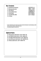
The box contents are for reference only. Box Contents GA-M720-US3 motherboard Motherboard driver disk User's Manual Quick Installation Guide One IDE cable Two SATA 3Gb/s cables I/O Shield • The box contents above are subject to ...
The box contents are for reference only. Box Contents GA-M720-US3 motherboard Motherboard driver disk User's Manual Quick Installation Guide One IDE cable Two SATA 3Gb/s cables I/O Shield • The box contents above are subject to ...
Manual
Page 8
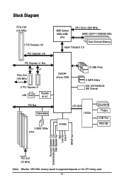
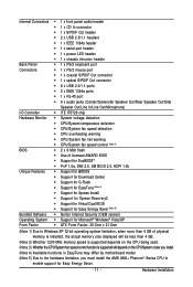
Block Diagram PCIe CLK (100 MHz) 1 PCI Express x16 PCI Express x16 AMD Socket AM2+/AM2 CPU CPU CLK+/-(200 MHz) DDR2 1200(Note)/1066/800 MHz Dual Channel Memory Hyper Transport 3.0 PCI Express x1 Bus x1 x1 PCIe CLK (100 MHz) 2 PCI Express x1 LAN RJ45 Realtek 8111C PCI Bus TSB43AB23 3 IEEE 1394a 4 PCI NVIDIA® nForce 720D 12 USB Ports 6 SATA 3Gb/s ATA-133/100/66/33 IDE Channel LPC BUS IT8720 CODEC Dual BIOS Floppy COM Port PS/2 KB Surround Speaker Out Center/Subwoofer Speaker Out Side Speaker Out MIC Line-Out Line-In SPDIF Out PCI CLK (33 MHz) (Note) Whether 1200 MHz memory ...
Block Diagram PCIe CLK (100 MHz) 1 PCI Express x16 PCI Express x16 AMD Socket AM2+/AM2 CPU CPU CLK+/-(200 MHz) DDR2 1200(Note)/1066/800 MHz Dual Channel Memory Hyper Transport 3.0 PCI Express x1 Bus x1 x1 PCIe CLK (100 MHz) 2 PCI Express x1 LAN RJ45 Realtek 8111C PCI Bus TSB43AB23 3 IEEE 1394a 4 PCI NVIDIA® nForce 720D 12 USB Ports 6 SATA 3Gb/s ATA-133/100/66/33 IDE Channel LPC BUS IT8720 CODEC Dual BIOS Floppy COM Port PS/2 KB Surround Speaker Out Center/Subwoofer Speaker Out Side Speaker Out MIC Line-Out Line-In SPDIF Out PCI CLK (33 MHz) (Note) Whether 1200 MHz memory ...
Manual
Page 9
If you are connected tightly and securely. • When handling the motherboard, avoid touching any metal leads or connectors. • It is best to wear an electrostatic discharge (ESD) wrist strap when handling electronic components such as a result of electrostatic discharge (ESD). Prior to installation, carefully read the user's manual and follow these procedures: • Prior to the use of an antistatic pad or within an electrostatic shielding container. • Before unplugging the power supply cable from the power outlet before installing or removing the motherboard or ...
If you are connected tightly and securely. • When handling the motherboard, avoid touching any metal leads or connectors. • It is best to wear an electrostatic discharge (ESD) wrist strap when handling electronic components such as a result of electrostatic discharge (ESD). Prior to installation, carefully read the user's manual and follow these procedures: • Prior to the use of an antistatic pad or within an electrostatic shielding container. • Before unplugging the power supply cable from the power outlet before installing or removing the motherboard or ...
Manual
Page 10
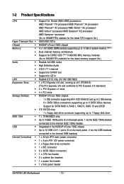
...drive connector 1 x IDE connector 6 x SATA 3Gb/s connectors 1 x CPU fan header 2 x system fan headers 1 x power fan header 1 x front panel header GA-M720-US3 Motherboard - 10 - 1-2 Product Specifications CPU Hyper Transport Bus Chipset Memory Audio ...memory (Note 1) Dual channel memory architecture Support for DDR2 1200 (Note 2)/1066/800 MHz memory modules (Go to GIGABYTE's website for the latest memory support list.) Realtek ALC888 codec High Definition Audio 2/4/5.1/7.1-channel Support for S/PDIF Out ...
...drive connector 1 x IDE connector 6 x SATA 3Gb/s connectors 1 x CPU fan header 2 x system fan headers 1 x power fan header 1 x front panel header GA-M720-US3 Motherboard - 10 - 1-2 Product Specifications CPU Hyper Transport Bus Chipset Memory Audio ...memory (Note 1) Dual channel memory architecture Support for DDR2 1200 (Note 2)/1066/800 MHz memory modules (Go to GIGABYTE's website for the latest memory support list.) Realtek ALC888 codec High Definition Audio 2/4/5.1/7.1-channel Support for S/PDIF Out ...
Manual
Page 11
Internal Connectors 1 x front panel audio header 1 x CD In connector 1 x S/PDIF Out header 2 x USB 2.0/1.1 headers 1 x IEEE 1394a header 1 x serial port header 1 x power LED header 1 x chassis intrusion header Back Panel 1 x PS/2 keyboard port Connectors 1 x PS/2 mouse port 1 x coaxial S/PDIF Out connector 1 x optical S/PDIF Out connector 8 x USB 2.0/1.1 ports 2 x IEEE 1394a ports 1 x RJ-45 port 6 x audio jacks (Center/Subwoofer ...
Internal Connectors 1 x front panel audio header 1 x CD In connector 1 x S/PDIF Out header 2 x USB 2.0/1.1 headers 1 x IEEE 1394a header 1 x serial port header 1 x power LED header 1 x chassis intrusion header Back Panel 1 x PS/2 keyboard port Connectors 1 x PS/2 mouse port 1 x coaxial S/PDIF Out connector 1 x optical S/PDIF Out connector 8 x USB 2.0/1.1 ports 2 x IEEE 1394a ports 1 x RJ-45 port 6 x audio jacks (Center/Subwoofer ...
Manual
Page 12
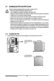
A Small Triangle Mark Denotes Pin One of the Socket AM2 Socket A Small Triangle Marking Denotes CPU Pin One AM2+/AM2 CPU GA-M720-US3 Motherboard - 12 - Locate the pin one of the CPU. It is not installed, otherwise overheating and damage of the CPU may occur. • Set...and thin layer of thermal grease on the computer if the CPU cooler is not recom- mended that the motherboard supports the CPU. (Go to GIGABYTE's website for the peripherals. 1-3 Installing the CPU and CPU Cooler Read the following guidelines before you wish to set beyond the standard specifications, please...
A Small Triangle Mark Denotes Pin One of the Socket AM2 Socket A Small Triangle Marking Denotes CPU Pin One AM2+/AM2 CPU GA-M720-US3 Motherboard - 12 - Locate the pin one of the CPU. It is not installed, otherwise overheating and damage of the CPU may occur. • Set...and thin layer of thermal grease on the computer if the CPU cooler is not recom- mended that the motherboard supports the CPU. (Go to GIGABYTE's website for the peripherals. 1-3 Installing the CPU and CPU Cooler Read the following guidelines before you wish to set beyond the standard specifications, please...
Manual
Page 13
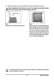
Before installing the CPU, make sure to turn off the computer and unplug the power cord from the power outlet to prevent damage to correctly install the CPU into the motherboard CPU socket. Make sure that the CPU pins fit perfectly into the CPU socket. Do not force the CPU into their holes. Step 2: Align the CPU pin one finger down on the CPU socket and gently insert the CPU into the fully locked position. The CPU cannot fit in if oriented incorrectly. Hardware Installation Adjust the CPU orientation if this occurs. - 13 - Once the CPU is positioned into its ...
Before installing the CPU, make sure to turn off the computer and unplug the power cord from the power outlet to prevent damage to correctly install the CPU into the motherboard CPU socket. Make sure that the CPU pins fit perfectly into the CPU socket. Do not force the CPU into their holes. Step 2: Align the CPU pin one finger down on the CPU socket and gently insert the CPU into the fully locked position. The CPU cannot fit in if oriented incorrectly. Hardware Installation Adjust the CPU orientation if this occurs. - 13 - Once the CPU is positioned into its ...
Manual
Page 14
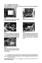
... cooler to correctly install the CPU cooler on the CPU. (The following procedure uses the GIGABYTE cooler as the example.) Step 1: Apply an even and thin layer of thermal grease on the surface of the retention frame. GA-M720-US3 Motherboard - 14 - Step 2: Place the CPU cooler on the retention frame. 1-3-2 Installing the CPU...
... cooler to correctly install the CPU cooler on the CPU. (The following procedure uses the GIGABYTE cooler as the example.) Step 1: Apply an even and thin layer of thermal grease on the surface of the retention frame. GA-M720-US3 Motherboard - 14 - Step 2: Place the CPU cooler on the retention frame. 1-3-2 Installing the CPU...
Manual
Page 15
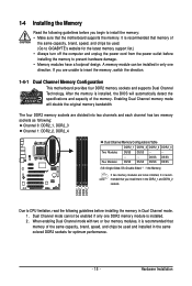
...) If two memory modules are to be installed, it is recommended that memory of the same capacity, brand, speed, and chips be used . (Go to GIGABYTE's website for optimum performance. - 15 - Dual Channel mode cannot be enabled if only one direction. The four DDR2 memory sockets are unable to insert the...
...) If two memory modules are to be installed, it is recommended that memory of the same capacity, brand, speed, and chips be used . (Go to GIGABYTE's website for optimum performance. - 15 - Dual Channel mode cannot be enabled if only one direction. The four DDR2 memory sockets are unable to insert the...
Manual
Page 16
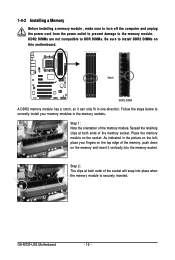
... damage to the memory module. Notch DDR2 DIMM A DDR2 memory module has a notch, so it vertically into place when the memory module is securely inserted. GA-M720-US3 Motherboard - 16 -
... damage to the memory module. Notch DDR2 DIMM A DDR2 memory module has a notch, so it vertically into place when the memory module is securely inserted. GA-M720-US3 Motherboard - 16 -
Manual
Page 17
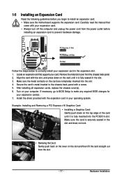
Locate an expansion slot that came with the expansion card in the slot. 3. Make sure the metal contacts on the top edge of the card until it is fully seated in your expansion card(s). 7. If necessary, go to BIOS Setup to make any required BIOS changes for your operating system. Remove the metal slot cover from the slot. - 17 - Carefully read the manual that supports your expansion card. • Always turn off the computer and unplug the power cord from the power outlet before you begin to install an expansion card: • Make sure the motherboard supports the ...
Locate an expansion slot that came with the expansion card in the slot. 3. Make sure the metal contacts on the top edge of the card until it is fully seated in your expansion card(s). 7. If necessary, go to BIOS Setup to make any required BIOS changes for your operating system. Remove the metal slot cover from the slot. - 17 - Carefully read the manual that supports your expansion card. • Always turn off the computer and unplug the power cord from the power outlet before you begin to install an expansion card: • Make sure the motherboard supports the ...
Manual
Page 18
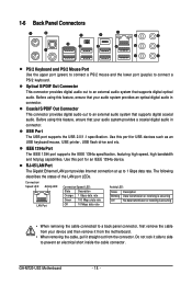
... a PS/2 mouse and the lower port (purple) to 1 Gbps data rate. Use this feature, ensure that your audio system provides a coaxial digital audio in connector. GA-M720-US3 Motherboard - 18 - IEEE 1394a Port The IEEE 1394 port supports the IEEE 1394a specification, featuring high speed, high bandwidth and hotplug capabilities. Coaxial S/PDIF Out...
... a PS/2 mouse and the lower port (purple) to 1 Gbps data rate. Use this feature, ensure that your audio system provides a coaxial digital audio in connector. GA-M720-US3 Motherboard - 18 - IEEE 1394a Port The IEEE 1394 port supports the IEEE 1394a specification, featuring high speed, high bandwidth and hotplug capabilities. Coaxial S/PDIF Out...

Manual
Page 19
Side Speaker Out Jack (Gray) Use this audio jack for a headphone or 2-channel speaker. Use this audio jack to connect side speakers in a 4/5.1/7.1-channel audio configuration. Only microphones still MUST be reconfigured to the instructions on setting up a 2/4/5.1/ 7.1-channel audio configuration in jack. Refer to perform different functions via the audio software. Line Out Jack (Green) The default line out jack. Microphones must be used to connect center/subwoofer speakers in jack ( ). In addition to the default speakers settings, the ~ audio jacks can be connected to ...
Side Speaker Out Jack (Gray) Use this audio jack for a headphone or 2-channel speaker. Use this audio jack to connect side speakers in a 4/5.1/7.1-channel audio configuration. Only microphones still MUST be reconfigured to the instructions on setting up a 2/4/5.1/ 7.1-channel audio configuration in jack. Refer to perform different functions via the audio software. Line Out Jack (Green) The default line out jack. Microphones must be used to connect center/subwoofer speakers in jack ( ). In addition to the default speakers settings, the ~ audio jacks can be connected to ...
Manual
Page 20
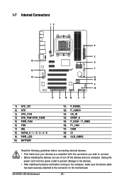
GA-M720-US3 Motherboard - 20 - 1-7 Internal Connectors 13 5 2 12 8 7 14 13 10 15 4 19 17 6 18 16 9 11 1) ATX_12V 2) ATX 3) CPU_FAN 4) SYS_FAN1/SYS_FAN2 5) PWR_FAN 6) FDD 7) IDE 8) SATA2_0 / 1 / 2 / 3 / 4 / 5 9) PWR_LED ...
GA-M720-US3 Motherboard - 20 - 1-7 Internal Connectors 13 5 2 12 8 7 14 13 10 15 4 19 17 6 18 16 9 11 1) ATX_12V 2) ATX 3) CPU_FAN 4) SYS_FAN1/SYS_FAN2 5) PWR_FAN 6) FDD 7) IDE 8) SATA2_0 / 1 / 2 / 3 / 4 / 5 9) PWR_LED ...
Manual
Page 21
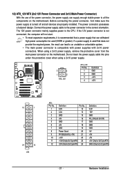
Connect the power supply cable to the CPU. If a power supply is used that can withstand high power consumption be used (500W or greater). Hardware Installation The power connector possesses a foolproof design. The 12V power connector mainly supplies power to the power connector in the correct orientation. Do not insert the power supply cable into pins under the protective cover when using a 2x12 power supply, remove the protective cover from the main power connector on the motherboard. 1/2) ATX_12V/ATX (2x2 12V Power Connector and 2x12 Main Power Connector) With the use of the power...
Connect the power supply cable to the CPU. If a power supply is used that can withstand high power consumption be used (500W or greater). Hardware Installation The power connector possesses a foolproof design. The 12V power connector mainly supplies power to the power connector in the correct orientation. Do not insert the power supply cable into pins under the protective cover when using a 2x12 power supply, remove the protective cover from the main power connector on the motherboard. 1/2) ATX_12V/ATX (2x2 12V Power Connector and 2x12 Main Power Connector) With the use of the power...
