Manual
Page 4
...of Contents Box Contents ...6 OptionalItems...6 GA-M720-US3 Motherboard Layout 7 Block Diagram...8 Chapter 1 Hardware Installation 9 1-1 Installation Precautions 9 1-2 Product Specifications 10 1-3 Installing the CPU and CPU Cooler 12 1-3-1 Installing the CPU 12 1-3-2 Installing the CPU Cooler 14 1-4 Installing the Memory 15 1-4-1 Dual Channel Memory Configuration 15 1-4-2 Installing a Memory 16 1-5 Installing an Expansion Card 17 1-6 Back Panel Connectors 18 1-7 Internal Connectors 20 Chapter 2 BIOS Setup 31 2-1 Startup Screen 32 2-2 The Main Menu 33 2-3 MB Intelligent Tweaker...
...of Contents Box Contents ...6 OptionalItems...6 GA-M720-US3 Motherboard Layout 7 Block Diagram...8 Chapter 1 Hardware Installation 9 1-1 Installation Precautions 9 1-2 Product Specifications 10 1-3 Installing the CPU and CPU Cooler 12 1-3-1 Installing the CPU 12 1-3-2 Installing the CPU Cooler 14 1-4 Installing the Memory 15 1-4-1 Dual Channel Memory Configuration 15 1-4-2 Installing a Memory 16 1-5 Installing an Expansion Card 17 1-6 Back Panel Connectors 18 1-7 Internal Connectors 20 Chapter 2 BIOS Setup 31 2-1 Startup Screen 32 2-2 The Main Menu 33 2-3 MB Intelligent Tweaker...
Manual
Page 5
... Utilities 62 4-2-1 Updating the BIOS with the Q-Flash Utility 62 4-2-2 Updating the BIOS with the @BIOS Utility 65 4-3 EasyTune 6 ...66 4-4 Easy Energy Saver 67 Chapter 5 Appendix ...69 5-1 Configuring SATA Hard Drive(s 69 5-1-1 Configuring the Onboard SATA Controller 69 5-1-2 Making a SATA RAID/AHCI Driver Diskette for Windows XP 74 5-1-3 Installing the SATA RAID Driver and Operating System 75 5-2 Configuring Audio Input and Output 79 5-2-1 Configuring 2/4/5.1/7.1-Channel Audio 79 5-2-2 Configuring S/PDIF Out 81 5-2-3 Configuring Microphone Recording 82 5-2-4 Using the Sound...
... Utilities 62 4-2-1 Updating the BIOS with the Q-Flash Utility 62 4-2-2 Updating the BIOS with the @BIOS Utility 65 4-3 EasyTune 6 ...66 4-4 Easy Energy Saver 67 Chapter 5 Appendix ...69 5-1 Configuring SATA Hard Drive(s 69 5-1-1 Configuring the Onboard SATA Controller 69 5-1-2 Making a SATA RAID/AHCI Driver Diskette for Windows XP 74 5-1-3 Installing the SATA RAID Driver and Operating System 75 5-2 Configuring Audio Input and Output 79 5-2-1 Configuring 2/4/5.1/7.1-Channel Audio 79 5-2-2 Configuring S/PDIF Out 81 5-2-3 Configuring Microphone Recording 82 5-2-4 Using the Sound...
Manual
Page 10
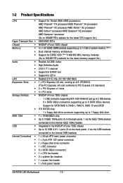
...) 1 x PCI Express x16 slot, running at x16 (PCIEX16) (The PCI Express x16 slot conforms to PCI Express 2.0 standard.) 2 x PCI Express x1 slots 4 x PCI slots NVIDIA® nForce 720D chipset: - 1 x IDE connector supporting ATA-133/100/66/33 and up to 2 IDE devices - 6 x SATA 3Gb/s connectors supporting up to the internal USB headers) 1 x 24-pin ATX main power connector 1 x 4-pin ATX 12V power connector 1 x floppy disk drive connector 1 x IDE connector 6 x SATA 3Gb/s connectors 1 x CPU fan header 2 x system fan headers 1 x power fan header 1 x front panel header GA-M720-US3 Motherboard - 10...
...) 1 x PCI Express x16 slot, running at x16 (PCIEX16) (The PCI Express x16 slot conforms to PCI Express 2.0 standard.) 2 x PCI Express x1 slots 4 x PCI slots NVIDIA® nForce 720D chipset: - 1 x IDE connector supporting ATA-133/100/66/33 and up to 2 IDE devices - 6 x SATA 3Gb/s connectors supporting up to the internal USB headers) 1 x 24-pin ATX main power connector 1 x 4-pin ATX 12V power connector 1 x floppy disk drive connector 1 x IDE connector 6 x SATA 3Gb/s connectors 1 x CPU fan header 2 x system fan headers 1 x power fan header 1 x front panel header GA-M720-US3 Motherboard - 10...
Manual
Page 11
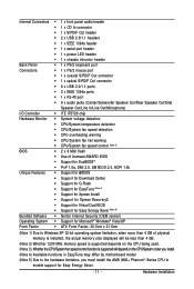
...1 x serial port header 1 x power LED header 1 x chassis intrusion header Back Panel 1 x PS/2 keyboard port Connectors 1 x PS/2 mouse port 1 x coaxial S/PDIF Out connector 1 x optical S/PDIF Out connector 8 x USB 2.0/1.1 ports 2 x IEEE 1394a ports 1 x RJ-45 port 6 x audio jacks (Center/Subwoofer Speaker Out/Rear Speaker Out/Side Speaker Out/Line In/Line Out/Microphone) I/O Controller iTE IT8720 chip Hardware Monitor System voltage detection CPU/System temperature...
...1 x serial port header 1 x power LED header 1 x chassis intrusion header Back Panel 1 x PS/2 keyboard port Connectors 1 x PS/2 mouse port 1 x coaxial S/PDIF Out connector 1 x optical S/PDIF Out connector 8 x USB 2.0/1.1 ports 2 x IEEE 1394a ports 1 x RJ-45 port 6 x audio jacks (Center/Subwoofer Speaker Out/Rear Speaker Out/Side Speaker Out/Line In/Line Out/Microphone) I/O Controller iTE IT8720 chip Hardware Monitor System voltage detection CPU/System temperature...
Manual
Page 17
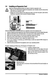
... the slot. - 17 - 1-5 Installing an Expansion Card Read the following guidelines before installing an expansion card to correctly install your card. Carefully read the manual that supports your expansion card in your expansion card. • Always turn off the computer and unplug the power cord from the chassis back panel. 2. If necessary, go to BIOS Setup to install an expansion card: • Make sure the motherboard supports the expansion card. Install the driver provided...
... the slot. - 17 - 1-5 Installing an Expansion Card Read the following guidelines before installing an expansion card to correctly install your card. Carefully read the manual that supports your expansion card in your expansion card. • Always turn off the computer and unplug the power cord from the chassis back panel. 2. If necessary, go to BIOS Setup to install an expansion card: • Make sure the motherboard supports the expansion card. Install the driver provided...
Manual
Page 22
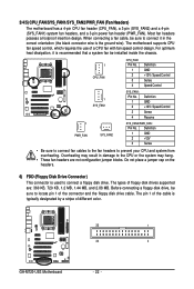
... insertion design. The motherboard supports CPU fan speed control, which requires the use of floppy disk drives supported are not configuration jumper blocks. For optimum heat dissipation, it in damage to connect a floppy disk drive. Do not place a jumper cap on the headers. 6) FDD (Floppy Disk Drive Connector) This connector is recommended that a system fan be installed inside the chassis. 1 CPU_FAN CPU_FAN: Pin No. 1 2 3 4 Definition GND +12V / Speed Control Sense Speed Control 1 SYS_FAN1 SYS_FAN1: Pin No. 1 2 3 4 Definition GND +12V / Speed Control Sense Reserve 1 PWR_FAN...
... insertion design. The motherboard supports CPU fan speed control, which requires the use of floppy disk drives supported are not configuration jumper blocks. For optimum heat dissipation, it in damage to connect a floppy disk drive. Do not place a jumper cap on the headers. 6) FDD (Floppy Disk Drive Connector) This connector is recommended that a system fan be installed inside the chassis. 1 CPU_FAN CPU_FAN: Pin No. 1 2 3 4 Definition GND +12V / Speed Control Sense Speed Control 1 SYS_FAN1 SYS_FAN1: Pin No. 1 2 3 4 Definition GND +12V / Speed Control Sense Reserve 1 PWR_FAN...
Manual
Page 29
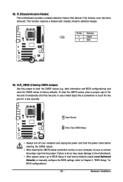
... computer and unplug the power cord from the jumper. Definition 1 1 Signal 2 GND 19) CLR_CMOS (Clearing CMOS Jumper) Use this jumper to factory defaults. Failure to do so may cause damage to the motherboard. • After system restart, go to BIOS Setup to load factory defaults (select Load Optimized Defaults) or manually configure the BIOS settings (refer to touch the two pins for BIOS configurations). - 29 - Hardware Installation This function requires a chassis with chassis intrusion detection design.
... computer and unplug the power cord from the jumper. Definition 1 1 Signal 2 GND 19) CLR_CMOS (Clearing CMOS Jumper) Use this jumper to factory defaults. Failure to do so may cause damage to the motherboard. • After system restart, go to BIOS Setup to load factory defaults (select Load Optimized Defaults) or manually configure the BIOS settings (refer to touch the two pins for BIOS configurations). - 29 - Hardware Installation This function requires a chassis with chassis intrusion detection design.
Manual
Page 34
... system operations. Set Supervisor Password Change, set , or disable password. An user password only allows you can also carry out this function to load the BIOS settings from BIOS If your CPU, memory, etc. Standard CMOS Features Use this menu to configure the system time and date, hard drive types, floppy disk drive types, and the type of reconfiguring the BIOS settings. First enter the profile name (to erase the default profile name, use the SPACE key) and then press...
... system operations. Set Supervisor Password Change, set , or disable password. An user password only allows you can also carry out this function to load the BIOS settings from BIOS If your CPU, memory, etc. Standard CMOS Features Use this menu to configure the system time and date, hard drive types, floppy disk drive types, and the type of reconfiguring the BIOS settings. First enter the profile name (to erase the default profile name, use the SPACE key) and then press...
Manual
Page 41
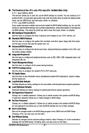
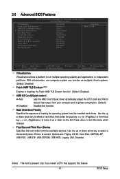
... - Options are: Floppy, LS120, Hard Disk, CDROM, ZIP, USB-FDD, USB-ZIP, USB-CDROM, USB-HDD, Legacy LAN, Disabled. (Note) This item is present only if you install a CPU that supports this function. Use the up or down arrow key to select a hard drive, then press the plus key (or ) or the minus key (or ) to move it up or down on the list. 2-5 Advanced BIOS Features CMOS Setup Utility-Copyright (C) 1984-2008 Award Software Advanced BIOS Features Virtualization Patch AMD...
... - Options are: Floppy, LS120, Hard Disk, CDROM, ZIP, USB-FDD, USB-ZIP, USB-CDROM, USB-HDD, Legacy LAN, Disabled. (Note) This item is present only if you install a CPU that supports this function. Use the up or down arrow key to select a hard drive, then press the plus key (or ) or the minus key (or ) to move it up or down on the list. 2-5 Advanced BIOS Features CMOS Setup Utility-Copyright (C) 1984-2008 Award Software Advanced BIOS Features Virtualization Patch AMD...
Manual
Page 42
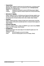
...of the monitor display from the installed PCI graphics card or PCI Express graphics card. Disabled displays normal POST message. (Default: Enabled) Init Display First Specifies the first initiation of the hard drive and to silently perform unattended tasks while in a low-power mode that appears off (Default: Disabled) Full Screen LOGO Show Allows you enter BIOS Setup. PCI Slot Sets the PCI graphics card as the first display. (Default) GA-M720-US3 Motherboard - 42 - After configuring this item, set the password(s) under the Set Supervisor/User Password item in Windows XP...
...of the monitor display from the installed PCI graphics card or PCI Express graphics card. Disabled displays normal POST message. (Default: Enabled) Init Display First Specifies the first initiation of the hard drive and to silently perform unattended tasks while in a low-power mode that appears off (Default: Disabled) Full Screen LOGO Show Allows you enter BIOS Setup. PCI Slot Sets the PCI graphics card as the first display. (Default) GA-M720-US3 Motherboard - 42 - After configuring this item, set the password(s) under the Set Supervisor/User Password item in Windows XP...
Manual
Page 43
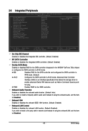
2-6 Integrated Peripherals CMOS Setup Utility-Copyright (C) 1984-2008 Award Software Integrated Peripherals On-Chip IDE Channel NV SATA Controller Onchip SATA Mode Onboard Audio Function Onboard 1394 Onboard LAN Control SMART LAN Onboard LAN Boot ROM Onboard Serial Port OnChip USB USB Memory Type USB Keyboard Support USB Mouse Support Legacy USB storage detect [Enabled] [Enabled] [IDE] [Auto] [Enabled] [Enabled] [Press Enter] [Disabled] [3F8/IRQ4] [V1.1+V2.0] [SHADOW] [Disabled] [Disabled] [Enabled] Item Help Menu Level Move Enter: Select F5: Previous Values +/-/PU/PD:...
2-6 Integrated Peripherals CMOS Setup Utility-Copyright (C) 1984-2008 Award Software Integrated Peripherals On-Chip IDE Channel NV SATA Controller Onchip SATA Mode Onboard Audio Function Onboard 1394 Onboard LAN Control SMART LAN Onboard LAN Boot ROM Onboard Serial Port OnChip USB USB Memory Type USB Keyboard Support USB Mouse Support Legacy USB storage detect [Enabled] [Enabled] [IDE] [Auto] [Enabled] [Enabled] [Press Enter] [Disabled] [3F8/IRQ4] [V1.1+V2.0] [SHADOW] [Disabled] [Disabled] [Enabled] Item Help Menu Level Move Enter: Select F5: Previous Values +/-/PU/PD:...

Manual
Page 45
... devices. Options are : Auto, 2F8/IRQ3, 3F8/IRQ4(default), 3E8/IRQ4, 2E8/IRQ3, Disabled. Onboard LAN Boot ROM Allows you to decide whether to detect USB storage devices, including USB flash drives and USB hard drives during the POST. (Default: Enabled) - 45 - USB Keyboard Support Allows USB keyboard to be used in MS-DOS. (Default: Disabled) USB Mouse Support Allows USB mouse to be used in MS-DOS. (Default: Disabled) Legacy USB storage detect Determines whether to activate the boot ROM integrated with the onboard LAN chip. (Default: Disabled) Onboard Serial Port Enables...
... devices. Options are : Auto, 2F8/IRQ3, 3F8/IRQ4(default), 3E8/IRQ4, 2E8/IRQ3, Disabled. Onboard LAN Boot ROM Allows you to decide whether to detect USB storage devices, including USB flash drives and USB hard drives during the POST. (Default: Enabled) - 45 - USB Keyboard Support Allows USB keyboard to be used in MS-DOS. (Default: Disabled) USB Mouse Support Allows USB mouse to be used in MS-DOS. (Default: Disabled) Legacy USB storage detect Determines whether to activate the boot ROM integrated with the onboard LAN chip. (Default: Disabled) Onboard Serial Port Enables...

Manual
Page 50
... BIOS autodetect the type of CPU fan installed and sets the optimal CPU fan control mode. (Default) Voltage Sets Voltage mode for a 4-pin CPU fan. PWM Sets PWM mode for a 3-pin CPU fan. If disabled, system fan runs at full speed. (Default: Enabled) CPU Smart FAN Mode Specifies how to Enabled. System/CPU Warning Temperature Sets the warning threshold for system/CPU temperature. You can adjust the fan speed with EasyTune based on system requirements. If disabled, CPU fan runs at full speed. (Default: Enabled) GA-M720-US3 Motherboard - 50 - This item is configurable...
... BIOS autodetect the type of CPU fan installed and sets the optimal CPU fan control mode. (Default) Voltage Sets Voltage mode for a 4-pin CPU fan. PWM Sets PWM mode for a 3-pin CPU fan. If disabled, system fan runs at full speed. (Default: Enabled) CPU Smart FAN Mode Specifies how to Enabled. System/CPU Warning Temperature Sets the warning threshold for system/CPU temperature. You can adjust the fan speed with EasyTune based on system requirements. If disabled, CPU fan runs at full speed. (Default: Enabled) GA-M720-US3 Motherboard - 50 - This item is configurable...
Manual
Page 62
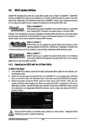
... USB flash drive or hard drive must use the key during the POST or pressing the key in BIOS Setup. During the POST, press the key to ensure normal system operation. However, if the main BIOS is @BIOSTM? @BIOS allows you can access Q-Flash by adding one more physical BIOS chip. What is DualBIOSTM? With Q-Flash you to update the system BIOS while in RAID/AHCI mode or a hard drive attached to your motherboard model. 2. From GIGABYTE's website, download the latest compressed BIOS update file...
... USB flash drive or hard drive must use the key during the POST or pressing the key in BIOS Setup. During the POST, press the key to ensure normal system operation. However, if the main BIOS is @BIOSTM? @BIOS allows you can access Q-Flash by adding one more physical BIOS chip. What is DualBIOSTM? With Q-Flash you to update the system BIOS while in RAID/AHCI mode or a hard drive attached to your motherboard model. 2. From GIGABYTE's website, download the latest compressed BIOS update file...
Manual
Page 63
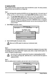
... RAID/AHCI mode or a hard drive attached to an independent IDE/SATA controller, use the up or down arrow key to select Update BIOS from Drive and press . • The Save Main BIOS to Drive option allows you to save the BIOS file to begin the BIOS update. Insert the floppy disk containing the BIOS file into the floppy disk drive. In the main menu of the system reading the BIOS file from Drive Sa0vefilBeI(Os)SfotounDdrive :Move ESC:Reset :Power Off Total size : 0 Free size...
... RAID/AHCI mode or a hard drive attached to an independent IDE/SATA controller, use the up or down arrow key to select Update BIOS from Drive and press . • The Save Main BIOS to Drive option allows you to save the BIOS file to begin the BIOS update. Insert the floppy disk containing the BIOS file into the floppy disk drive. In the main menu of the system reading the BIOS file from Drive Sa0vefilBeI(Os)SfotounDdrive :Move ESC:Reset :Power Off Total size : 0 Free size...
Manual
Page 66
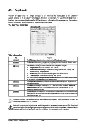
... monitor hardware temperature, voltage and fan speed and set . You can select memory module on the installed CPU and motherboard. The Smart tab allows you do overclock/overvoltage in EasyTune 6 may result in Easy mode/Advanced mode, be changed linearly based on the installed memory module(s). Incorrectly doing overclock/overvoltage may differ by motherboard model. GA-M720-US3 Motherboard - 66 - The Memory tab provides information on the CPU temperature thresholds you to install additional software. The Graphics tab allows you set temperature/fan speed...
... monitor hardware temperature, voltage and fan speed and set . You can select memory module on the installed CPU and motherboard. The Smart tab allows you do overclock/overvoltage in EasyTune 6 may result in Easy mode/Advanced mode, be changed linearly based on the installed memory module(s). Incorrectly doing overclock/overvoltage may differ by motherboard model. GA-M720-US3 Motherboard - 66 - The Memory tab provides information on the CPU temperature thresholds you to install additional software. The Graphics tab allows you set temperature/fan speed...
Manual
Page 69
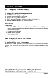
.... (Note 2) Before you begin Please prepare: • At least two SATA hard drives (to ensure optimal performance, it is recommended that you do not want to create RAID array on the motherboard. Then connect the power connector from your computer Attach one hard drive. • An empty formatted floppy disk. • Windows Vista/XP setup disk. • Motherboard driver disk. 5-1-1 Configuring the Onboard SATA Controller A. Configure a RAID array in BIOS Setup. B. Install SATA hard drive(s) in your power supply to AHCI or RAID mode. - 69 -
.... (Note 2) Before you begin Please prepare: • At least two SATA hard drives (to ensure optimal performance, it is recommended that you do not want to create RAID array on the motherboard. Then connect the power connector from your computer Attach one hard drive. • An empty formatted floppy disk. • Windows Vista/XP setup disk. • Motherboard driver disk. 5-1-1 Configuring the Onboard SATA Controller A. Configure a RAID array in BIOS Setup. B. Install SATA hard drive(s) in your power supply to AHCI or RAID mode. - 69 -

Manual
Page 70
... Peripherals. Step 1: Turn on the motherboard you have and the BIOS version. CMOS Setup Utility-Copyright (C) 1984-2008 Award Software Integrated Peripherals On-Chip IDE Channel NV SATA Controller Onchip SATA Mode Onboard Audio Function Onboard 1394 Onboard LAN Control SMART LAN Onboard LAN Boot ROM Onboard Serial Port OnChip USB USB Memory Type USB Keyboard Support USB Mouse Support Legacy USB storage detect [Enabled] [Enabled] [RAID] [Auto] [Enabled] [Enabled] [Press Enter] [Disabled] [3F8/IRQ4] [V1.1+V2.0] [SHADOW] [Disabled] [Disabled] [Enabled] Item Help Menu Level...
... Peripherals. Step 1: Turn on the motherboard you have and the BIOS version. CMOS Setup Utility-Copyright (C) 1984-2008 Award Software Integrated Peripherals On-Chip IDE Channel NV SATA Controller Onchip SATA Mode Onboard Audio Function Onboard 1394 Onboard LAN Control SMART LAN Onboard LAN Boot ROM Onboard Serial Port OnChip USB USB Memory Type USB Keyboard Support USB Mouse Support Legacy USB storage detect [Enabled] [Enabled] [RAID] [Auto] [Enabled] [Enabled] [Press Enter] [Disabled] [3F8/IRQ4] [V1.1+V2.0] [SHADOW] [Disabled] [Disabled] [Enabled] Item Help Menu Level...
Manual
Page 74
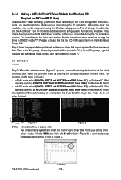
... motherboard driver disk to a floppy disk. For installing Windows Vista, please directly load the SATA RAID driver from the startup disk. Once at the A:\> prompt, change to your optical drive folder, double click the MENU.exe file in the BootDrv folder (Figure 3). A command prompt window will then automatically zip and transfer this driver file to install the SATA controller driver during the Windows setup process. For example, in the menu in your system. At the D:\> prompt, type...
... motherboard driver disk to a floppy disk. For installing Windows Vista, please directly load the SATA RAID driver from the startup disk. Once at the A:\> prompt, change to your optical drive folder, double click the MENU.exe file in the BootDrv folder (Figure 3). A command prompt window will then automatically zip and transfer this driver file to install the SATA controller driver during the Windows setup process. For example, in the menu in your system. At the D:\> prompt, type...

Manual
Page 85
...why the light is equipped with power/ amplifier. Q:How do the beeps emitted during the POST. A: The following Award BIOS beep code descriptions may help you identify possible computer problems. (For reference only.) 1 short: System boots successfully 2 short: CMOS setting error 1 long, 1 short: Memory or motherboard error 1 long, 2 short: Monitor or graphics card error 1 long, 3 short: Keyboard error 1 long, 9 short: BIOS ROM error Continuous long beeps: Graphics card not inserted properly Continuous short beeps: Power error - 85 - If not, try a speaker with an internal amplifier...
...why the light is equipped with power/ amplifier. Q:How do the beeps emitted during the POST. A: The following Award BIOS beep code descriptions may help you identify possible computer problems. (For reference only.) 1 short: System boots successfully 2 short: CMOS setting error 1 long, 1 short: Memory or motherboard error 1 long, 2 short: Monitor or graphics card error 1 long, 3 short: Keyboard error 1 long, 9 short: BIOS ROM error Continuous long beeps: Graphics card not inserted properly Continuous short beeps: Power error - 85 - If not, try a speaker with an internal amplifier...


