User Manual
Page 4
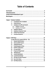
...GA-K8VT800-RH Motherboard Layout 7 Block Diagram ...8 Chapter 1 Hardware Installation 9 1-1 Considerations Prior to Installation 9 1-2 Feature Summary 10 1-3 Installation of the CPU and Heatsink 12 1-3-1 Installation of the CPU 12 1-3-2 Installation of the Heatsink 13 1-4 Installation of Memory 13 1-5 Installation of Expansion Cards 15 1-6 I/O Back Panel Introduction 16 1-7 Connectors Introduction 17 Chapter 2 BIOS... Setup 29 The Main Menu (For example: BIOS Ver. : E8 30 2-1 Standard CMOS Features 32 2-2 Advanced BIOS Features 34 2-3 ...
...GA-K8VT800-RH Motherboard Layout 7 Block Diagram ...8 Chapter 1 Hardware Installation 9 1-1 Considerations Prior to Installation 9 1-2 Feature Summary 10 1-3 Installation of the CPU and Heatsink 12 1-3-1 Installation of the CPU 12 1-3-2 Installation of the Heatsink 13 1-4 Installation of Memory 13 1-5 Installation of Expansion Cards 15 1-6 I/O Back Panel Introduction 16 1-7 Connectors Introduction 17 Chapter 2 BIOS... Setup 29 The Main Menu (For example: BIOS Ver. : E8 30 2-1 Standard CMOS Features 32 2-2 Advanced BIOS Features 34 2-3 ...
User Manual
Page 5
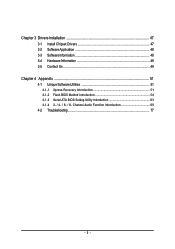
Channel Audio Function Introduction 69 4-2 Troubleshooting 77 - 5 - Chapter 3 Drivers Installation 47 3-1 Install Chipset Drivers 47 3-2 SoftwareApplication 48 3-3 Software Information 48 3-4 Hardware Information 49 3-5 Contact Us ...49 Chapter 4 Appendix 51 4-1 Unique Software Utilities 51 4-1-1 Xpress Recovery Introduction 51 4-1-2 Flash BIOS Method Introduction 54 4-1-3 Serial ATA BIOS Setting Utility Introduction 63 4-1-4 2- / 4- / 6- / 8-
Channel Audio Function Introduction 69 4-2 Troubleshooting 77 - 5 - Chapter 3 Drivers Installation 47 3-1 Install Chipset Drivers 47 3-2 SoftwareApplication 48 3-3 Software Information 48 3-4 Hardware Information 49 3-5 Contact Us ...49 Chapter 4 Appendix 51 4-1 Unique Software Utilities 51 4-1-1 Xpress Recovery Introduction 51 4-1-2 Flash BIOS Method Introduction 54 4-1-3 Serial ATA BIOS Setting Utility Introduction 63 4-1-4 2- / 4- / 6- / 8-
User Manual
Page 8
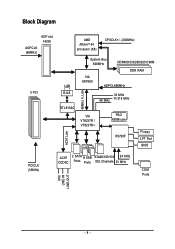
Block Diagram AGP slot 4X/8X AGPCLK (66MHz) 5 PCI AMD AthlonTM 64 processor (K8) CPUCLK+/- (200MHz) AC97 Link LAN RJ45 RTL8100C 66MHz V_Link System Bus 800MHz DDR400/333/266/200 DIMM DDR RAM VIA K8T800 AGPCLK66MHz 33 MHz 48 MHz 14.318 MHz VIA VT8237R / VT8237R+ PS/2 KB/Mouse IT8705F Floppy LPT Port BIOS PCICLK (33MHz) AC97 2 SATA 8 USB ATA66/100/133 24 MHz CODEC Ports Ports IDE Channels 33 MHz COM Ports MIC LINE-IN LINE-OUT - 8 -
Block Diagram AGP slot 4X/8X AGPCLK (66MHz) 5 PCI AMD AthlonTM 64 processor (K8) CPUCLK+/- (200MHz) AC97 Link LAN RJ45 RTL8100C 66MHz V_Link System Bus 800MHz DDR400/333/266/200 DIMM DDR RAM VIA K8T800 AGPCLK66MHz 33 MHz 48 MHz 14.318 MHz VIA VT8237R / VT8237R+ PS/2 KB/Mouse IT8705F Floppy LPT Port BIOS PCICLK (33MHz) AC97 2 SATA 8 USB ATA66/100/133 24 MHz CODEC Ports Ports IDE Channels 33 MHz COM Ports MIC LINE-IN LINE-OUT - 8 -

User Manual
Page 11
English Onboard SATA RAID Š Š Š Š Š BIOS Š Š Additional Features Š Š Overclocking Š Š Form Factor Š Onboard VT8237R / VT8237R+ chipset (SATA0, SATA1) supports data striping (RAID 0) or ... (RAID 1) function supports JBOD function supports data transfer rate of up to 150 MB/s supports a maximum of 2 SATA connections Use of licensed AWARD BIOS Supports Q-Flash Supports @BIOS Supports EasyTune Over Voltage via BIOS (CPU/ DDR/ AGP) Over Clock via BIOS (CPU) ATX form factor; 29.5cm x 21.5cm - 11 - Hardware Installation
English Onboard SATA RAID Š Š Š Š Š BIOS Š Š Additional Features Š Š Overclocking Š Š Form Factor Š Onboard VT8237R / VT8237R+ chipset (SATA0, SATA1) supports data striping (RAID 0) or ... (RAID 1) function supports JBOD function supports data transfer rate of up to 150 MB/s supports a maximum of 2 SATA connections Use of licensed AWARD BIOS Supports Q-Flash Supports @BIOS Supports EasyTune Over Voltage via BIOS (CPU/ DDR/ AGP) Over Clock via BIOS (CPU) ATX form factor; 29.5cm x 21.5cm - 11 - Hardware Installation
User Manual
Page 13
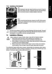
... heat sink paste on the motherboard so that the heat sink can properly function to prevent CPU overheating. The motherboard supports DDR memory modules, whereby BIOS will automatically detect memory capacity and specifications. Install all the heat sink components (Please refer to the heat sink manual for heat dissipation or using...
... heat sink paste on the motherboard so that the heat sink can properly function to prevent CPU overheating. The motherboard supports DDR memory modules, whereby BIOS will automatically detect memory capacity and specifications. Install all the heat sink components (Please refer to the heat sink manual for heat dissipation or using...
User Manual
Page 15
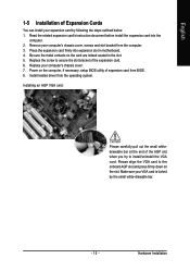
Install related driver from BIOS. 8. Installing an AGP VGA card: Please carefully pull out the small whitedrawable bar at the end of the expansion card. 6. Please align the VGA card ... try to the onboard AGP slot and press firmly down on the card are indeed seated in motherboard. 4. Power on the computer, if necessary, setup BIOS utility of expansion card from the operating system. Press the expansion card firmly into the computer. 2. Replace your computer's chassis cover, screws and slot bracket...
Install related driver from BIOS. 8. Installing an AGP VGA card: Please carefully pull out the small whitedrawable bar at the end of the expansion card. 6. Please align the VGA card ... try to the onboard AGP slot and press firmly down on the card are indeed seated in motherboard. 4. Power on the computer, if necessary, setup BIOS utility of expansion card from the operating system. Press the expansion card firmly into the computer. 2. Replace your computer's chassis cover, screws and slot bracket...
User Manual
Page 21
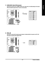
Definition 1 MPD+ 1 2 MPD- 3 MPD- - 21 - Definition 1 GND 1 7 2 TXP 3 TXN 4 GND 5 RXN 6 RXP 7 GND 8) PWR_LED PWR_LED is connect with the system power indicator to 150MB/s transfer rate. It will blink when the system enters suspend mode. Hardware Installation English 7) SATA0/ SATA1 (Serial ATA Connector) Serial ATA can provide up to indicate whether the system is on/off. Pin No. Pin No. Please refer to the BIOS setting for the Serial ATA and install the proper driver in order to work properly.
Definition 1 MPD+ 1 2 MPD- 3 MPD- - 21 - Definition 1 GND 1 7 2 TXP 3 TXN 4 GND 5 RXN 6 RXP 7 GND 8) PWR_LED PWR_LED is connect with the system power indicator to 150MB/s transfer rate. It will blink when the system enters suspend mode. Hardware Installation English 7) SATA0/ SATA1 (Serial ATA Connector) Serial ATA can provide up to indicate whether the system is on/off. Pin No. Pin No. Please refer to the BIOS setting for the Serial ATA and install the proper driver in order to work properly.
User Manual
Page 29
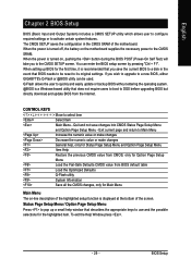
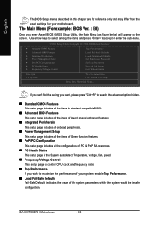
... Q-Flash utility System Information Save all the CMOS changes, only for the first time, it is a Windows-based utility that BIOS needs to a new BIOS, either GIGABYTE's Q-Flash or @BIOS utility can enter the BIOS setup screen by pressing "Ctrl + F1". When setting up a small help , only for Status Page Setup Menu and Option Page...
... Q-Flash utility System Information Save all the CMOS changes, only for the first time, it is a Windows-based utility that BIOS needs to a new BIOS, either GIGABYTE's Q-Flash or @BIOS utility can enter the BIOS setup screen by pressing "Ctrl + F1". When setting up a small help , only for Status Page Setup Menu and Option Page...
User Manual
Page 30
...only and may differ from the exact settings for your motherboard. The Main Menu (For example: BIOS Ver. : E8) Once you wish to accept or enter the sub-menu. GA-K8VT800-RH Motherboard - 30 - CMOS Setup Utility-Copyright (C) 1984-2004 Award Software ` Standard CMOS ...Features ` Advanced BIOS Features ` Integrated Peripherals ` Power Management Setup ` PnP/PCI Configurations ` PC Health Status ` Frequency/Voltage Control ...
...only and may differ from the exact settings for your motherboard. The Main Menu (For example: BIOS Ver. : E8) Once you wish to accept or enter the sub-menu. GA-K8VT800-RH Motherboard - 30 - CMOS Setup Utility-Copyright (C) 1984-2004 Award Software ` Standard CMOS ...Features ` Advanced BIOS Features ` Integrated Peripherals ` Power Management Setup ` PnP/PCI Configurations ` PC Health Status ` Frequency/Voltage Control ...
User Manual
Page 31
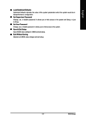
It allows you to limit access to the system. „ Save & Exit Setup Save CMOS value settings to Setup. „ Set User Password Change, set , or disable password. English „ Load Optimized Defaults Optimized Defaults indicates the value of the system parameters which the system would be in best performance configuration. „ Set Supervisor Password Change, set , or disable password. BIOS Setup It allows you to limit access to the system and Setup, or just to CMOS and exit setup. „ Exit Without Saving Abandon all CMOS value changes and exit setup. - 31 -
It allows you to limit access to the system. „ Save & Exit Setup Save CMOS value settings to Setup. „ Set User Password Change, set , or disable password. English „ Load Optimized Defaults Optimized Defaults indicates the value of the system parameters which the system would be in best performance configuration. „ Set Supervisor Password Change, set , or disable password. BIOS Setup It allows you to limit access to the system and Setup, or just to CMOS and exit setup. „ Exit Without Saving Abandon all CMOS value changes and exit setup. - 31 -
User Manual
Page 32
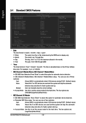
...time is display only The month, Jan. IDE Channel 0 Master/Slave; User can use one of three methods: Auto None Allows BIOS to automatically detect IDE devices during POST. (Default value) None Select this to select this option for faster system start up . IDE... the access mode for automatic device detection. Jan. For example, 1 p.m. Access Mode Use this if no IDE devices are : Large/Auto(default:Auto) GA-K8VT800-RH Motherboard - 32 - Extended IDE Drive setup You can manually input the correct settings. is , , , . IDE Channel 1 Master/Slave setup....
...time is display only The month, Jan. IDE Channel 0 Master/Slave; User can use one of three methods: Auto None Allows BIOS to automatically detect IDE devices during POST. (Default value) None Select this to select this option for faster system start up . IDE... the access mode for automatic device detection. Jan. For example, 1 p.m. Access Mode Use this if no IDE devices are : Large/Auto(default:Auto) GA-K8VT800-RH Motherboard - 32 - Extended IDE Drive setup You can manually input the correct settings. is , , , . IDE Channel 1 Master/Slave setup....

User Manual
Page 33
.... Both Drive A & B are 3 mode Floppy Drives. All, But Keyboard The system boot will not stop for a keyboard or disk error; BIOS Setup Drive A/Drive B The category identifies the types of base (or conventional) memory installed in the CPU's memory address map. it will not stop... for a disk error; Extended Memory The BIOS determines how much extended memory is 3 mode Floppy Drive. Enter the appropriate option based on the outside drive casing. Memory The category is...
.... Both Drive A & B are 3 mode Floppy Drives. All, But Keyboard The system boot will not stop for a keyboard or disk error; BIOS Setup Drive A/Drive B The category identifies the types of base (or conventional) memory installed in the CPU's memory address map. it will not stop... for a disk error; Extended Memory The BIOS determines how much extended memory is 3 mode Floppy Drive. Enter the appropriate option based on the outside drive casing. Memory The category is...

User Manual
Page 34
... system can not boot and can not access to Setup will be denied if the correct password is not entered at the prompt. (Default value) GA-K8VT800-RH Motherboard - 34 - First / Second / Third Boot Device Floppy Select your boot device priority by CDROM. Use < > or < > to select a ... to move it down the list. Press to move it up, or to exit this menu. English 2-2 Advanced BIOS Features CMOS Setup Utility-Copyright (C) 1984-2004 Award Software Advanced BIOS Features ` Hard Disk Boot Priority First Boot Device Second Boot Device Third Boot Device Password Check [Press Enter] [...
... system can not boot and can not access to Setup will be denied if the correct password is not entered at the prompt. (Default value) GA-K8VT800-RH Motherboard - 34 - First / Second / Third Boot Device Floppy Select your boot device priority by CDROM. Use < > or < > to select a ... to move it down the list. Press to move it up, or to exit this menu. English 2-2 Advanced BIOS Features CMOS Setup Utility-Copyright (C) 1984-2004 Award Software Advanced BIOS Features ` Hard Disk Boot Priority First Boot Device Second Boot Device Third Boot Device Password Check [Press Enter] [...
User Manual
Page 35
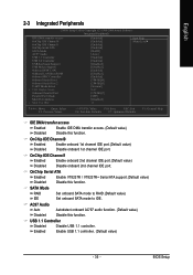
.... SATA Mode RAID Set onboard SATA mode to RAID.(Default value) IDE Set onboard SATA mode to IDE. Enabled Enable USB 1.1 controller. (Default value) - 35 - BIOS Setup English 2-3 Integrated Peripherals CMOS Setup Utility-Copyright (C) 1984-2004 Award Software Integrated Peripherals IDE DMA transfer access OnChip IDE Channel 0 OnChip IDE Channel 1 OnChip...
.... SATA Mode RAID Set onboard SATA mode to RAID.(Default value) IDE Set onboard SATA mode to IDE. Enabled Enable USB 1.1 controller. (Default value) - 35 - BIOS Setup English 2-3 Integrated Peripherals CMOS Setup Utility-Copyright (C) 1984-2004 Award Software Integrated Peripherals IDE DMA transfer access OnChip IDE Channel 0 OnChip IDE Channel 1 OnChip...

User Manual
Page 36
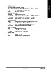
... I/O chip UART to Normal mode.(Default value) IrDA Set onboard I /O chip UART to invoke the boot ROM of Onboard I/O chip. GA-K8VT800-RH Motherboard - 36 - OnBoard LAN Boot ROM This function decide whether to ASKIR mode. UART Mode Select This item allows you to IrDA... English USB 2.0 Controller Disabled Disable USB 2.0 controller. Enable onboard Serial port 1 and address is 2E8. Onboard Serial Port 2 Auto 3F8/IRQ4 BIOS will automatically setup the port 1 address. 3F8/IRQ4 2F8/IRQ3 Enable onboard Serial port 1 and address is 3F8. (Default value) Enable onboard Serial...
... I/O chip UART to Normal mode.(Default value) IrDA Set onboard I /O chip UART to invoke the boot ROM of Onboard I/O chip. GA-K8VT800-RH Motherboard - 36 - OnBoard LAN Boot ROM This function decide whether to ASKIR mode. UART Mode Select This item allows you to IrDA... English USB 2.0 Controller Disabled Disable USB 2.0 controller. Enable onboard Serial port 1 and address is 2E8. Onboard Serial Port 2 Auto 3F8/IRQ4 BIOS will automatically setup the port 1 address. 3F8/IRQ4 2F8/IRQ3 Enable onboard Serial port 1 and address is 3F8. (Default value) Enable onboard Serial...
User Manual
Page 37
... function. (Default value) Midi Port IRQ 5 Set Midi Port IRQ to 5. 10 Set Midi Port IRQ to 330. Using Parallel port as Enhanced Parallel Port. BIOS Setup ECP ECP+EPP Using Parallel port as Extended Capabilities Port. Onboard Parallel Port Disabled 378/IRQ7 Disable onboard LPT port. Enable onboard LPT port...
... function. (Default value) Midi Port IRQ 5 Set Midi Port IRQ to 5. 10 Set Midi Port IRQ to 330. Using Parallel port as Enhanced Parallel Port. BIOS Setup ECP ECP+EPP Using Parallel port as Extended Capabilities Port. Onboard Parallel Port Disabled 378/IRQ7 Disable onboard LPT port. Enable onboard LPT port...

User Manual
Page 39
.../Time to POWER ON system. Enabled Enable Modem Ring Resume function. (Default value) Resume by Alarm You can awake the system from any suspend state. BIOS Setup Enable PME as wake up event. (Default value) Modem Ring Resume An incoming call via modem can set "Resume by Alarm is Enabled. English...
.../Time to POWER ON system. Enabled Enable Modem Ring Resume function. (Default value) Resume by Alarm You can awake the system from any suspend state. BIOS Setup Enable PME as wake up event. (Default value) Modem Ring Resume An incoming call via modem can set "Resume by Alarm is Enabled. English...
User Manual
Page 41
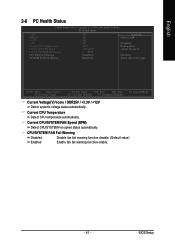
... F10: Save ESC: Exit F6: Fail-Safe Defaults F7: Optimized Defaults F1: General Help Current Voltage(V) Vcore / DDR25V / +3.3V / +12V Detect system's voltage status automatically. BIOS Setup CPU/SYSTEM FAN Fail Warning Disabled Disable fan fail warning function disable. (Default value) Enabled Enable fan fail warning function enable. - 41 - Current CPU...
... F10: Save ESC: Exit F6: Fail-Safe Defaults F7: Optimized Defaults F1: General Help Current Voltage(V) Vcore / DDR25V / +3.3V / +12V Detect system's voltage status automatically. BIOS Setup CPU/SYSTEM FAN Fail Warning Disabled Disable fan fail warning function disable. (Default value) Enabled Enable fan fail warning function enable. - 41 - Current CPU...

User Manual
Page 43
...as mentioned above. 2-9 Load Fail-Safe Defaults CMOS Setup Utility-Copyright (C) 1984-2004 Award Software ` Standard CMOS Features ` Advanced BIOS Features ` Integrated Peripherals ` Power Management Setup ` PnP/PCI Configurations ` PC Health Status ` Frequency/Voltage Control Esc: Quit ...may occur. 2-8 Top Performance CMOS Setup Utility-Copyright (C) 1984-2004 Award Software ` Standard CMOS Features Top Performance ` Advanced BIOS Features Load Fail-Safe Defaults ` Integrated Peripherals Top Performance Load Optimized Defaults ` Power Management Setup Set Supervisor Password ` `...
...as mentioned above. 2-9 Load Fail-Safe Defaults CMOS Setup Utility-Copyright (C) 1984-2004 Award Software ` Standard CMOS Features ` Advanced BIOS Features ` Integrated Peripherals ` Power Management Setup ` PnP/PCI Configurations ` PC Health Status ` Frequency/Voltage Control Esc: Quit ...may occur. 2-8 Top Performance CMOS Setup Utility-Copyright (C) 1984-2004 Award Software ` Standard CMOS Features Top Performance ` Advanced BIOS Features Load Fail-Safe Defaults ` Integrated Peripherals Top Performance Load Optimized Defaults ` Power Management Setup Set Supervisor Password ` `...
User Manual
Page 44
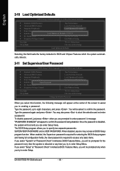
... may access all BIOS Setup program function. Type the password again and press . GA-K8VT800-RH Motherboard - ...44 - To disable password, just press when you are prompted to abort the selection and not enter a password. Once the password is disabled, the system will appear at the center of the screen to confirm the password. The BIOS... Optimized Defaults CMOS Setup Utility-Copyright (C) 1984-2004 Award Software ` Standard CMOS Features ` Advanced BIOS Features ` Integrated Peripherals ` Power Management Setup ` PnP/PCI Configurations ` PC Health Status ` ...
... may access all BIOS Setup program function. Type the password again and press . GA-K8VT800-RH Motherboard - ...44 - To disable password, just press when you are prompted to abort the selection and not enter a password. Once the password is disabled, the system will appear at the center of the screen to confirm the password. The BIOS... Optimized Defaults CMOS Setup Utility-Copyright (C) 1984-2004 Award Software ` Standard CMOS Features ` Advanced BIOS Features ` Integrated Peripherals ` Power Management Setup ` PnP/PCI Configurations ` PC Health Status ` ...


