User Manual
Page 4
...the CPU 12 1-3-2 Installation of the Heatsink 13 1-4 Installation of Memory 13 1-5 Installation of Expansion Cards 15 1-6 I/O Back Panel Introduction 16 1-7 Connectors Introduction 17 Chapter 2 BIOS Setup 29 The Main Menu (For example: BIOS Ver. : E8 30 2-1 Standard CMOS Features 32 2-2 Advanced BIOS Features 34 2-3 IntegratedPeripherals 35 2-4 Power Management Setup 38 2-5 PnP/PCI Configurations 40 2-6 PC Health Status 41 2-7 Frequency/Voltage Control 42 2-8 TopPerformance 43 2-9 Load Fail-Safe Defaults 43 2-10 Load Optimized Defaults 44 2-11 Set Supervisor/User Password 44...
...the CPU 12 1-3-2 Installation of the Heatsink 13 1-4 Installation of Memory 13 1-5 Installation of Expansion Cards 15 1-6 I/O Back Panel Introduction 16 1-7 Connectors Introduction 17 Chapter 2 BIOS Setup 29 The Main Menu (For example: BIOS Ver. : E8 30 2-1 Standard CMOS Features 32 2-2 Advanced BIOS Features 34 2-3 IntegratedPeripherals 35 2-4 Power Management Setup 38 2-5 PnP/PCI Configurations 40 2-6 PC Health Status 41 2-7 Frequency/Voltage Control 42 2-8 TopPerformance 43 2-9 Load Fail-Safe Defaults 43 2-10 Load Optimized Defaults 44 2-11 Set Supervisor/User Password 44...
User Manual
Page 10
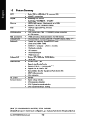
... Summary CPU Chipset Memory Slots IDE Connections FDD Connections Onboard SATA Peripherals Onboard LAN Onboard Audio I/O Control Hardware Monitor Š Socket 754 for AMD AthlonTM 64 processor (K8) Š 1600MT/s system bus Š Northbridge: VIA K8T800 Š Southbridge: VIA VT8237R / VT8237R+ Š 3 DDR DIMM memory slots (supports up an 8 channel audio configuration, you must use SATA (1.5Gb/s) hard disks. (Note 2) To set up to 3GB) Š Supports DDR 400/333/266/200 DIMMs Š 1 AGP slot supports 8X/4X(1.5V) mode Š 5 PCI slots Š 2 IDE connection (UDMA...
... Summary CPU Chipset Memory Slots IDE Connections FDD Connections Onboard SATA Peripherals Onboard LAN Onboard Audio I/O Control Hardware Monitor Š Socket 754 for AMD AthlonTM 64 processor (K8) Š 1600MT/s system bus Š Northbridge: VIA K8T800 Š Southbridge: VIA VT8237R / VT8237R+ Š 3 DDR DIMM memory slots (supports up an 8 channel audio configuration, you must use SATA (1.5Gb/s) hard disks. (Note 2) To set up to 3GB) Š Supports DDR 400/333/266/200 DIMMs Š 1 AGP slot supports 8X/4X(1.5V) mode Š 5 PCI slots Š 2 IDE connection (UDMA...

User Manual
Page 20
... IDE connector can then connect to two IDE devices (hard drive or optical drive). Before attaching the IDE cable, please take note of the foolproof groove in the IDE connector. 39 1 IDE1 IDE2 40 2 GA-K8VT800-RH Motherboard - 20 - English 5) FDD (FDD Connector) The FDD connector is used to connect the FDD cable while the other as Slave (for information on settings, please refer to the instructions located on one IDE cable, and the single IDE cable...
... IDE connector can then connect to two IDE devices (hard drive or optical drive). Before attaching the IDE cable, please take note of the foolproof groove in the IDE connector. 39 1 IDE1 IDE2 40 2 GA-K8VT800-RH Motherboard - 20 - English 5) FDD (FDD Connector) The FDD connector is used to connect the FDD cable while the other as Slave (for information on settings, please refer to the instructions located on one IDE cable, and the single IDE cable...
User Manual
Page 21
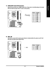
Hardware Installation Definition 1 MPD+ 1 2 MPD- 3 MPD- - 21 - English 7) SATA0/ SATA1 (Serial ATA Connector) Serial ATA can provide up to indicate whether the system is connect with the system power indicator to 150MB/s transfer rate. Definition 1 GND 1 7 2 TXP 3 TXN 4 GND 5 RXN 6 RXP 7 GND 8) PWR_LED PWR_LED is on/off. Pin No. Please refer to the BIOS setting for the Serial ATA and install the proper driver in order to work properly. Pin No. It will blink when the system enters suspend mode.
Hardware Installation Definition 1 MPD+ 1 2 MPD- 3 MPD- - 21 - English 7) SATA0/ SATA1 (Serial ATA Connector) Serial ATA can provide up to indicate whether the system is connect with the system power indicator to 150MB/s transfer rate. Definition 1 GND 1 7 2 TXP 3 TXN 4 GND 5 RXN 6 RXP 7 GND 8) PWR_LED PWR_LED is on/off. Pin No. Please refer to the BIOS setting for the Serial ATA and install the proper driver in order to work properly. Pin No. It will blink when the system enters suspend mode.
User Manual
Page 22
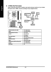
...Switch HD (IDE Hard Disk Active LED) (Blue) SPEAK (Speaker Connector) (Amber) RES (Reset Switch) (Green) PW (Power Switch) (Red) MSG(Message LED/Power/Sleep LED) (Yellow) NC (Purple) Pin 1: LED anode(+) Pin 2: LED cathode(-) Pin 1: Power Pin 2- Pin 3: NC Pin 4: Data(-) Open: Normal Close: Reset Hardware System Open: Normal Close: Power On/Off Pin 1: LED anode(+) Pin 2: LED cathode(-) NC GA-K8VT800-RH Motherboard - 22 - Active LED Soft Power Connector Speaker Connector PW- English 9) F_PANEL (Front Panel Jumper) Please connect the power LED, PC speaker, reset switch and power...
...Switch HD (IDE Hard Disk Active LED) (Blue) SPEAK (Speaker Connector) (Amber) RES (Reset Switch) (Green) PW (Power Switch) (Red) MSG(Message LED/Power/Sleep LED) (Yellow) NC (Purple) Pin 1: LED anode(+) Pin 2: LED cathode(-) Pin 1: Power Pin 2- Pin 3: NC Pin 4: Data(-) Open: Normal Close: Reset Hardware System Open: Normal Close: Power On/Off Pin 1: LED anode(+) Pin 2: LED cathode(-) NC GA-K8VT800-RH Motherboard - 22 - Active LED Soft Power Connector Speaker Connector PW- English 9) F_PANEL (Front Panel Jumper) Please connect the power LED, PC speaker, reset switch and power...

User Manual
Page 24
English 12) SPDIF_IO (SPDIF In / Out Connector) The SPDIF output is capable of the SPDIF_IO connector. Use SPDIF in feature only when your nearest dealer for optional SUR_CEN cable. 2 8 1 7 Pin No. 1 2 3 4 5 6 7 8 Definition SUR OUTL SUR OUTR GND No Pin CENTER_OUT BASS_OUT AUX_L AUX_R GA-K8VT800-RH Motherboard - 24 - Check the pin assignment carefully while you connect the SPDIF cable, incorrect connection between the cable and connector will make the device unable to...
English 12) SPDIF_IO (SPDIF In / Out Connector) The SPDIF output is capable of the SPDIF_IO connector. Use SPDIF in feature only when your nearest dealer for optional SUR_CEN cable. 2 8 1 7 Pin No. 1 2 3 4 5 6 7 8 Definition SUR OUTL SUR OUTR GND No Pin CENTER_OUT BASS_OUT AUX_L AUX_R GA-K8VT800-RH Motherboard - 24 - Check the pin assignment carefully while you connect the SPDIF cable, incorrect connection between the cable and connector will make the device unable to...
User Manual
Page 30
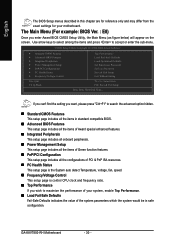
... Utility, the Main Menu (as figure below) will appear on the screen. English The BIOS Setup menus described in safe configuration. CMOS Setup Utility-Copyright (C) 1984-2004 Award Software ` Standard CMOS Features ` Advanced BIOS Features ` Integrated Peripherals ` Power Management Setup ` PnP/PCI Configurations ` PC Health Status ` Frequency/Voltage Control Esc: Quit F8: Q-Flash Top Performance Load Fail-Safe Defaults Load Optimized Defaults Set Supervisor Password Set User Password Save & Exit Setup Exit Without Saving KLJI: Select Item F10: Save & Exit Setup Time, Date, Hard Disk Type...
... Utility, the Main Menu (as figure below) will appear on the screen. English The BIOS Setup menus described in safe configuration. CMOS Setup Utility-Copyright (C) 1984-2004 Award Software ` Standard CMOS Features ` Advanced BIOS Features ` Integrated Peripherals ` Power Management Setup ` PnP/PCI Configurations ` PC Health Status ` Frequency/Voltage Control Esc: Quit F8: Q-Flash Top Performance Load Fail-Safe Defaults Load Optimized Defaults Set Supervisor Password Set User Password Save & Exit Setup Exit Without Saving KLJI: Select Item F10: Save & Exit Setup Time, Date, Hard Disk Type...
User Manual
Page 32
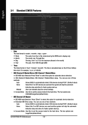
... IDE HDD Auto-Detection Press "Enter" to select this option for the hard drive. The four options are : Large/Auto(default:Auto) GA-K8VT800-RH Motherboard - 32 - User can use one of three methods: Auto None Allows BIOS to automatically detect IDE devices during POST. (Default value) None Select this to Sat, determined by the BIOS and is calculated base on the 24-hour military- Extended IDE Drive setup You can manually input the correct settings. For example, 1 p.m. IDE Channel...
... IDE HDD Auto-Detection Press "Enter" to select this option for the hard drive. The four options are : Large/Auto(default:Auto) GA-K8VT800-RH Motherboard - 32 - User can use one of three methods: Auto None Allows BIOS to automatically detect IDE devices during POST. (Default value) None Select this to Sat, determined by the BIOS and is calculated base on the 24-hour military- Extended IDE Drive setup You can manually input the correct settings. For example, 1 p.m. IDE Channel...
User Manual
Page 35
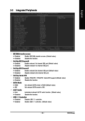
.... BIOS Setup OnChip IDE Channel0 Enabled Enable onboard 1st channel IDE port.(Default value) Disabled Disable onboard 1st channel IDE port. English 2-3 Integrated Peripherals CMOS Setup Utility-Copyright (C) 1984-2004 Award Software Integrated Peripherals IDE DMA transfer access OnChip IDE Channel 0 OnChip IDE Channel 1 OnChip Serial ATA SATA Mode AC97 Audio USB 1.1 Controller USB 2.0 Controller USB Keyboard Support USB Mouse Support Onboard H/W LAN OnBoard LAN Boot ROM Onboard FDC Controller Onboard Serial Port 1 Onboard Serial Port 2 UART Mode Select x UR2 Duplex Mode Onboard...
.... BIOS Setup OnChip IDE Channel0 Enabled Enable onboard 1st channel IDE port.(Default value) Disabled Disable onboard 1st channel IDE port. English 2-3 Integrated Peripherals CMOS Setup Utility-Copyright (C) 1984-2004 Award Software Integrated Peripherals IDE DMA transfer access OnChip IDE Channel 0 OnChip IDE Channel 1 OnChip Serial ATA SATA Mode AC97 Audio USB 1.1 Controller USB 2.0 Controller USB Keyboard Support USB Mouse Support Onboard H/W LAN OnBoard LAN Boot ROM Onboard FDC Controller Onboard Serial Port 1 Onboard Serial Port 2 UART Mode Select x UR2 Duplex Mode Onboard...

User Manual
Page 36
... Set onboard I/O chip UART to Normal mode.(Default value) IrDA Set onboard I /O chip UART to determine which Infra Red(IR) function of the onboard LAN chip. Enabled Enable USB 2.0 controller. (Default value) USB Keyboard Support Enabled Enable USB keyboard support. UART Mode Select This item allows you to ASKIR mode. Disabled Disable onboard Serial port 1. Onboard Serial Port 1 Auto BIOS will automatically setup the port 2 address. GA-K8VT800-RH Motherboard - 36 - Disabled Disable USB keyboard support. (Default value) USB Mouse Support Enabled Disabled Enable USB...
... Set onboard I/O chip UART to Normal mode.(Default value) IrDA Set onboard I /O chip UART to determine which Infra Red(IR) function of the onboard LAN chip. Enabled Enable USB 2.0 controller. (Default value) USB Keyboard Support Enabled Enable USB keyboard support. UART Mode Select This item allows you to ASKIR mode. Disabled Disable onboard Serial port 1. Onboard Serial Port 1 Auto BIOS will automatically setup the port 2 address. GA-K8VT800-RH Motherboard - 36 - Disabled Disable USB keyboard support. (Default value) USB Mouse Support Enabled Disabled Enable USB...

User Manual
Page 42
...-voltage. Auto Detect DIMM/PCI clk Enabled Disabled Detect the DIMM/PCI clock automatically. (Default value) Disable this function. Increase CPU voltage by 7.5%. For power end-user use only. Incorrectly using these features may cause your system. AGP OverVoltage Control Auto Set AGP voltage as CPU required. (Default value) Increase CPU voltage by 5%. English 2-7 Frequency/Voltage Control CMOS Setup Utility-Copyright (C) 1984-2004 Award Software Frequency/Voltage Control K8 CPU Clock Ratio Auto Detect DIMM/PCI Clk Spread Spectrum CPU Clock CPU OverVoltage Control...
...-voltage. Auto Detect DIMM/PCI clk Enabled Disabled Detect the DIMM/PCI clock automatically. (Default value) Disable this function. Increase CPU voltage by 7.5%. For power end-user use only. Incorrectly using these features may cause your system. AGP OverVoltage Control Auto Set AGP voltage as CPU required. (Default value) Increase CPU voltage by 5%. English 2-7 Frequency/Voltage Control CMOS Setup Utility-Copyright (C) 1984-2004 Award Software Frequency/Voltage Control K8 CPU Clock Ratio Auto Detect DIMM/PCI Clk Spread Spectrum CPU Clock CPU OverVoltage Control...

User Manual
Page 43
...CMOS Setup Utility-Copyright (C) 1984-2004 Award Software ` Standard CMOS Features Top Performance ` Advanced BIOS Features Load Fail-Safe Defaults ` Integrated Peripherals Top Performance Load Optimized Defaults ` Power Management Setup Set Supervisor Password ` ` PnP/PCI Configurations PC Health Status Disabled Enabled Set User Password Save & Exit Setup ` Frequency/Voltage Control Exit Without Saving Esc: Quit F8: Q-Flash KLJI: Select Item KL: Move ENTER: AcFc1e0p:t Save & Exit Setup ESC: Abort Load Fail-Safe Defaults If you disabling the option to avoid the problem...
...CMOS Setup Utility-Copyright (C) 1984-2004 Award Software ` Standard CMOS Features Top Performance ` Advanced BIOS Features Load Fail-Safe Defaults ` Integrated Peripherals Top Performance Load Optimized Defaults ` Power Management Setup Set Supervisor Password ` ` PnP/PCI Configurations PC Health Status Disabled Enabled Set User Password Save & Exit Setup ` Frequency/Voltage Control Exit Without Saving Esc: Quit F8: Q-Flash KLJI: Select Item KL: Move ENTER: AcFc1e0p:t Save & Exit Setup ESC: Abort Load Fail-Safe Defaults If you disabling the option to avoid the problem...
User Manual
Page 44
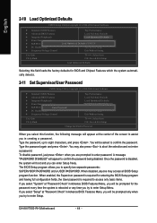
... BIOS Features Menu, you will boot and you select "System" at "Password Check" in creating a password. English 2-10 Load Optimized Defaults CMOS Setup Utility-Copyright (C) 1984-2004 Award Software ` Standard CMOS Features ` Advanced BIOS Features ` Integrated Peripherals ` Power Management Setup ` PnP/PCI Configurations ` PC Health Status ` Frequency/Voltage Control Esc: Quit F8: Q-Flash Top Performance Load Fail-Safe Defaults Load Optimized Defaults Set Supervisor Password Load Optimized DefaultsSe(tYU/Nse)r? Type the password, up to enter password. Once the password is disabled...
... BIOS Features Menu, you will boot and you select "System" at "Password Check" in creating a password. English 2-10 Load Optimized Defaults CMOS Setup Utility-Copyright (C) 1984-2004 Award Software ` Standard CMOS Features ` Advanced BIOS Features ` Integrated Peripherals ` Power Management Setup ` PnP/PCI Configurations ` PC Health Status ` Frequency/Voltage Control Esc: Quit F8: Q-Flash Top Performance Load Fail-Safe Defaults Load Optimized Defaults Set Supervisor Password Load Optimized DefaultsSe(tYU/Nse)r? Type the password, up to enter password. Once the password is disabled...
User Manual
Page 55
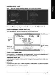
...Y button to operate the Q-Flash/Dual BIOS utility. CMOS Setup Utility-Copyright (C) 1984-2004 Award Software Standard CMOS Features Advanced BIOS Features Integrated Peripherals Power Management Setup PnP/PCI Configurations PC Health Status MB Intelligent Tweaker(M.I.T.) ESC: Quit F8: Dual BIOS/Q-Flash Select Language Load Fail-Safe Defaults Load Optimized Defaults Set Supervisor Password Set User Password Save & Exit Setup Exit Without Saving F3: Change Language F10: Save & Exit Setup Time, Date, Hard Disk Type... Appendix Pressing the buttons mentioned on your keyboards to enter BIOS...
...Y button to operate the Q-Flash/Dual BIOS utility. CMOS Setup Utility-Copyright (C) 1984-2004 Award Software Standard CMOS Features Advanced BIOS Features Integrated Peripherals Power Management Setup PnP/PCI Configurations PC Health Status MB Intelligent Tweaker(M.I.T.) ESC: Quit F8: Dual BIOS/Q-Flash Select Language Load Fail-Safe Defaults Load Optimized Defaults Set Supervisor Password Set User Password Save & Exit Setup Exit Without Saving F3: Change Language F10: Save & Exit Setup Time, Date, Hard Disk Type... Appendix Pressing the buttons mentioned on your keyboards to enter BIOS...
User Manual
Page 56
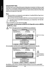
... Floppy Load Backup BIOS from the floppy disk. After BIOS file is listed. Dual BIOS Utility Boot From Main Bios Main ROM Type/Size SST 49LF003A Backup ROM Type/Size SST 49LF003A 512K 512K Wide Range Protection Disable 8KNXPU.FAbuatoBRooetcoF1vroefrimlye(s)MEfnoaauibnnldeBios 512K TFo5t:alRseifzreeCs:ho1Hp.3ay9ltMMOLanoianEdRrDrOoerMfauDDltaiStsaaFeDbttrtEoleieneLBgs:asicDzkeeul:pe9te11.50K Save Settings to the floppy disk. If you want to update BIOS using the Q-Flash utility. GA-K8VT800-RH Motherboard - 56 - As described in the Q-Flash menu and press Enter...
... Floppy Load Backup BIOS from the floppy disk. After BIOS file is listed. Dual BIOS Utility Boot From Main Bios Main ROM Type/Size SST 49LF003A Backup ROM Type/Size SST 49LF003A 512K 512K Wide Range Protection Disable 8KNXPU.FAbuatoBRooetcoF1vroefrimlye(s)MEfnoaauibnnldeBios 512K TFo5t:alRseifzreeCs:ho1Hp.3ay9ltMMOLanoianEdRrDrOoerMfauDDltaiStsaaFeDbttrtEoleieneLBgs:asicDzkeeul:pe9te11.50K Save Settings to the floppy disk. If you want to update BIOS using the Q-Flash utility. GA-K8VT800-RH Motherboard - 56 - As described in the Q-Flash menu and press Enter...

User Manual
Page 57
... Floppy Enter : Run :Move ESC:Reset F10:Power Off After system reboots, you may find the BIOS version on your boot screen becomes the one you exit Q-Flash. Please do not take out the floppy disk when it will begin to the Q-Flash menu when the BIOS updating procedure is completed. Dual BIOS Utility Boot From Main Bios Main ROM Type/Size SST 49LF003A Backup ROM Type/Size SST 49LF003A 512K 512K Wide Range Protection Disable Boot From Main Bios !A! Press any keys...
... Floppy Enter : Run :Move ESC:Reset F10:Power Off After system reboots, you may find the BIOS version on your boot screen becomes the one you exit Q-Flash. Please do not take out the floppy disk when it will begin to the Q-Flash menu when the BIOS updating procedure is completed. Dual BIOS Utility Boot From Main Bios Main ROM Type/Size SST 49LF003A Backup ROM Type/Size SST 49LF003A 512K 512K Wide Range Protection Disable Boot From Main Bios !A! Press any keys...
User Manual
Page 58
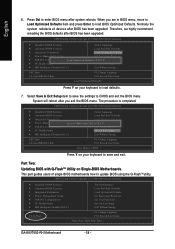
...: Dual BIOS/Q-Flash F3: Change Language F10: Save & Exit Setup Save Data to CMOS Press Y on Single-BIOS Motherboards. Therefore, we highly recommend reloading the BIOS defaults after BIOS has been upgraded. This part guides users of single-BIOS motherboards how to enter BIOS menu after you are in BIOS menu, move to Load Optimized Defaults item and press Enter to CMOS and exit the BIOS menu. Press Del to update BIOS using the Q-FlashTM utility. The procedure is completed. Part Two: Updating BIOS with Q-FlashTM Utility...
...: Dual BIOS/Q-Flash F3: Change Language F10: Save & Exit Setup Save Data to CMOS Press Y on Single-BIOS Motherboards. Therefore, we highly recommend reloading the BIOS defaults after BIOS has been upgraded. This part guides users of single-BIOS motherboards how to enter BIOS menu after you are in BIOS menu, move to Load Optimized Defaults item and press Enter to CMOS and exit the BIOS menu. Press Del to update BIOS using the Q-FlashTM utility. The procedure is completed. Part Two: Updating BIOS with Q-FlashTM Utility...
User Manual
Page 64
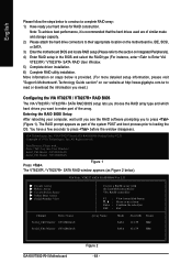
... RAID BIOS Setting Utility V2.31 Copyright (C) VIA Technologies, Inc. Scan Devices, Please wait... Entering the RAID BIOS Setup After rebooting your hard drives for RAID construction. You have a few seconds to next item Confirm the selection Exit Array Name Mode SATA SATA Size(GB) Status 111.79 Hdd 111.79 Hdd GA-K8VT800-RH Motherboard Figure 2 - 64 - VT8237 SATA RAID BIOS Ver 2.31 Create Array Delete Array Create/Delete Spare Select Boot Array Serial Number View Channel Drive...
... RAID BIOS Setting Utility V2.31 Copyright (C) VIA Technologies, Inc. Scan Devices, Please wait... Entering the RAID BIOS Setup After rebooting your hard drives for RAID construction. You have a few seconds to next item Confirm the selection Exit Array Name Mode SATA SATA Size(GB) Status 111.79 Hdd 111.79 Hdd GA-K8VT800-RH Motherboard Figure 2 - 64 - VT8237 SATA RAID BIOS Ver 2.31 Create Array Delete Array Create/Delete Spare Select Boot Array Serial Number View Channel Drive...
User Manual
Page 68
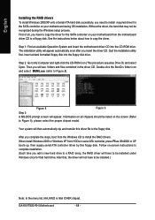
... this floppy disk. GA-K8VT800-RH Motherboard - 68 - When install Windows 2000 or Windows XP from HDDs in the driver CD. The installation utility will see folders and files contained in serial ATA controller, press F6 as Win2000 or XP boots up, then supply serial ATA controller driver by this driver file to the floppy disk. After that hard drive. English Installing the RAID drivers To install Windows 2000/XP onto a Serial ATA hard disk sucessfully, you need to install required driver for the SATA controller on your motherboard...
... this floppy disk. GA-K8VT800-RH Motherboard - 68 - When install Windows 2000 or Windows XP from HDDs in the driver CD. The installation utility will see folders and files contained in serial ATA controller, press F6 as Win2000 or XP boots up, then supply serial ATA controller driver by this driver file to the floppy disk. After that hard drive. English Installing the RAID drivers To install Windows 2000/XP onto a Serial ATA hard disk sucessfully, you need to install required driver for the SATA controller on your motherboard...
User Manual
Page 77
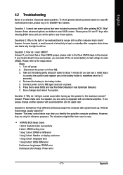
... are using is still on power. 6. If not, please change another speaker with an internal amplifier. What do I hear different continuous beeps from computer after updating BIOS. The situations might differ from MB. 3. Answer: In some options that 's why the light is equipped with power/amplifier and try again later. Connect power cord to case. AWARD BIOS Beep Codes 1 short: System boots successfully 2 short: CMOS setting error 1 long 1 short: DRAM or M/B error 1 long 2 short: Monitor or display card error 1 long 3 short: Keyboard error 1 long 9 short: BIOS ROM error...
... are using is still on power. 6. If not, please change another speaker with an internal amplifier. What do I hear different continuous beeps from computer after updating BIOS. The situations might differ from MB. 3. Answer: In some options that 's why the light is equipped with power/amplifier and try again later. Connect power cord to case. AWARD BIOS Beep Codes 1 short: System boots successfully 2 short: CMOS setting error 1 long 1 short: DRAM or M/B error 1 long 2 short: Monitor or display card error 1 long 3 short: Keyboard error 1 long 9 short: BIOS ROM error...


