User Manual
Page 4
Table of Contents GA-K8N51GMF-9 Motherboard Layout 6 Block Diagram ...7 Chapter 1 Hardware Installation 9 1-1 Considerations Prior to Installation 9 1-2 Feature Summary 10 1-3 Installation of the CPU and Fan Heat Sink ...of Memory 14 1-5 Installation of Expansion Cards 16 1-6 I/O Back Panel Introduction 17 1-7 Connectors Introduction 18 Chapter 2 BIOS Setup 29 The Main Menu (For example: BIOS Ver. : F1g 30 2-1 Standard CMOS Features 32 2-2 Advanced BIOS Features 34 2-3 IntegratedPeripherals 36 2-4 Power Management Setup 39 2-5 PnP/PCI Configurations 41 2-6 PC Health Status 42 2-7...
Table of Contents GA-K8N51GMF-9 Motherboard Layout 6 Block Diagram ...7 Chapter 1 Hardware Installation 9 1-1 Considerations Prior to Installation 9 1-2 Feature Summary 10 1-3 Installation of the CPU and Fan Heat Sink ...of Memory 14 1-5 Installation of Expansion Cards 16 1-6 I/O Back Panel Introduction 17 1-7 Connectors Introduction 18 Chapter 2 BIOS Setup 29 The Main Menu (For example: BIOS Ver. : F1g 30 2-1 Standard CMOS Features 32 2-2 Advanced BIOS Features 34 2-3 IntegratedPeripherals 36 2-4 Power Management Setup 39 2-5 PnP/PCI Configurations 41 2-6 PC Health Status 42 2-7...

User Manual
Page 5
Chapter 3 Drivers Installation 47 3-1 Install Chipset Drivers 47 3-2 SoftwareApplication 48 3-3 Software Information 48 3-4 Hardware Information 49 3-5 Contact Us ...49 Chapter 4 Appendix 51 4-1 Unique Software Utilities 51 4-1-1 EasyTune 5 Introduction 51 4-1-2 Xpress Recovery Introduction 52 4-1-3 Flash BIOS Method Introduction 55 4-1-4 Serial ATA BIOS Setting Utility Introduction 64 4-1-5 2- / 4- / 6- / 8- Channel Audio Function Introduction 70 4-2 Troubleshooting 75 - 5 -
Chapter 3 Drivers Installation 47 3-1 Install Chipset Drivers 47 3-2 SoftwareApplication 48 3-3 Software Information 48 3-4 Hardware Information 49 3-5 Contact Us ...49 Chapter 4 Appendix 51 4-1 Unique Software Utilities 51 4-1-1 EasyTune 5 Introduction 51 4-1-2 Xpress Recovery Introduction 52 4-1-3 Flash BIOS Method Introduction 55 4-1-4 Serial ATA BIOS Setting Utility Introduction 64 4-1-5 2- / 4- / 6- / 8- Channel Audio Function Introduction 70 4-2 Troubleshooting 75 - 5 -
User Manual
Page 11
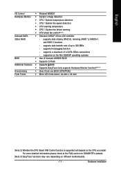
... - supports a maximum of up to 300 MB/s - Hardware Installation For more detailed information please check at the FAQ section on GIGABYTE's website. (Note 3) EasyTune functions may vary depending on the CPU you install. supports data transfer rate of 4 SATA 3Gb/s... CPU Smart FAN Control function is supported will depend on different motherboards. - 11 - English I/O Control Hardware Monitor Onboard SATA 3Gb/s RAID BIOS Additional Features Overclocking Form Factor Š Winbond W83627 Š System voltage detection Š CPU / System temperature detection Š CPU / System...
... - supports a maximum of up to 300 MB/s - Hardware Installation For more detailed information please check at the FAQ section on GIGABYTE's website. (Note 3) EasyTune functions may vary depending on the CPU you install. supports data transfer rate of 4 SATA 3Gb/s... CPU Smart FAN Control function is supported will depend on different motherboards. - 11 - English I/O Control Hardware Monitor Onboard SATA 3Gb/s RAID BIOS Additional Features Overclocking Form Factor Š Winbond W83627 Š System voltage detection Š CPU / System temperature detection Š CPU / System...
User Manual
Page 14
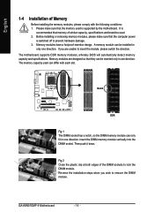
...only in only one direction. A memory module can be installed in one direction. The motherboard supports DDR memory modules, whereby BIOS will automatically detect memory capacity and specifications. Reverse the installation steps when you are designed so that the computer power is ...into the DIMM socket. English 1-4 Installation of Memory Before installing the memory modules, please comply with each slot. Then push it down. GA-K8N51GMF-9 Motherboard - 14 - Memory modules have a foolproof insertion design. If you wish to insert the module, please switch the direction. Memory...
...only in only one direction. A memory module can be installed in one direction. The motherboard supports DDR memory modules, whereby BIOS will automatically detect memory capacity and specifications. Reverse the installation steps when you are designed so that the computer power is ...into the DIMM socket. English 1-4 Installation of Memory Before installing the memory modules, please comply with each slot. Then push it down. GA-K8N51GMF-9 Motherboard - 14 - Memory modules have a foolproof insertion design. If you wish to insert the module, please switch the direction. Memory...

User Manual
Page 16
... VGA card is locked by following the steps outlined below: 1. Press the expansion card firmly into the computer. 2. Power on the slot. GA-K8N51GMF-9 Motherboard - 16 - Replace your expansion card by the small white-drawable bar. To install a VGA card or to release an installed card... the VGA card. Replace the screw to the onboard PCI Express x 16 slot and press firmly down on the computer, if necessary, setup BIOS utility of expansion card from the computer. 3. English 1-5 Installation of the expansion card. 6. Read the related expansion card's instruction document before ...
... VGA card is locked by following the steps outlined below: 1. Press the expansion card firmly into the computer. 2. Power on the slot. GA-K8N51GMF-9 Motherboard - 16 - Replace your expansion card by the small white-drawable bar. To install a VGA card or to release an installed card... the VGA card. Replace the screw to the onboard PCI Express x 16 slot and press firmly down on the computer, if necessary, setup BIOS utility of expansion card from the computer. 3. English 1-5 Installation of the expansion card. 6. Read the related expansion card's instruction document before ...
User Manual
Page 21
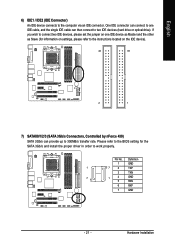
..., and the single IDE cable can provide up to two IDE devices (hard drive or optical drive). Pin No. Hardware Installation Please refer to the BIOS setting for information on settings, please refer to the instructions located on the IDE device). 40 39 2 1 7) SATAII0/1/2/3 (SATA 3Gb/s Connectors, Controlled by nForce 430...
..., and the single IDE cable can provide up to two IDE devices (hard drive or optical drive). Pin No. Hardware Installation Please refer to the BIOS setting for information on settings, please refer to the instructions located on the IDE device). 40 39 2 1 7) SATAII0/1/2/3 (SATA 3Gb/s Connectors, Controlled by nForce 430...
User Manual
Page 27
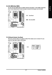
Definition 1 1 Signal 2 GND - 27 - Pin No. Hardware Installation To clear CMOS, temporarily short 1-2 pin. You can check the "Case Open" status in BIOS Setup. English 16) CLR_CMOS (Clear CMOS) You may clear the CMOS data to detect if the chassis cover is removed. Default doesn't include the jumper to prevent from improper use this header. 1 Open: Normal 1 Short: Clear CMOS 17) CI (Chassis Intrusion, Case Open) This 2-pin connector allows your system to its default values by this header.
Definition 1 1 Signal 2 GND - 27 - Pin No. Hardware Installation To clear CMOS, temporarily short 1-2 pin. You can check the "Case Open" status in BIOS Setup. English 16) CLR_CMOS (Clear CMOS) You may clear the CMOS data to detect if the chassis cover is removed. Default doesn't include the jumper to prevent from improper use this header. 1 Open: Normal 1 Short: Clear CMOS 17) CI (Chassis Intrusion, Case Open) This 2-pin connector allows your system to its default values by this header.

User Manual
Page 29
... Increase the numeric value or make changes Decrease the numeric value or make changes General help window that you to pop up BIOS for the highlighted item. English Chapter 2 BIOS Setup BIOS (Basic Input and Output System) includes a CMOS SETUP utility which allows user to configure required settings or to select item... SETUP screen. When the power is turned on -line description of the highlighted setup function is recommended that describes the appropriate keys to a new BIOS, either Gigabyte's Q-Flash or @BIOS utility can enter the BIOS setup screen by pressing "Ctrl + F1".
... Increase the numeric value or make changes Decrease the numeric value or make changes General help window that you to pop up BIOS for the highlighted item. English Chapter 2 BIOS Setup BIOS (Basic Input and Output System) includes a CMOS SETUP utility which allows user to configure required settings or to select item... SETUP screen. When the power is turned on -line description of the highlighted setup function is recommended that describes the appropriate keys to a new BIOS, either Gigabyte's Q-Flash or @BIOS utility can enter the BIOS setup screen by pressing "Ctrl + F1".

User Manual
Page 30
...differ from the exact settings for stability. „ Standard CMOS Features This setup page includes all the items in standard compatible BIOS. „ Advanced BIOS Features This setup page includes all the items of Award special enhanced features. „ Integrated Peripherals This setup page includes ...speed, etc. „ Frequency/Voltage Control This setup page is to accept or enter the sub-menu. GA-K8N51GMF-9 Motherboard - 30 - English The BIOS Setup menus described in the BIOS when somehow the system works not stable as figure below) will appear on the screen. This action makes...
...differ from the exact settings for stability. „ Standard CMOS Features This setup page includes all the items in standard compatible BIOS. „ Advanced BIOS Features This setup page includes all the items of Award special enhanced features. „ Integrated Peripherals This setup page includes ...speed, etc. „ Frequency/Voltage Control This setup page is to accept or enter the sub-menu. GA-K8N51GMF-9 Motherboard - 30 - English The BIOS Setup menus described in the BIOS when somehow the system works not stable as figure below) will appear on the screen. This action makes...

User Manual
Page 31
It allows you to limit access to the system and Setup, or just to CMOS and exit setup. „ Exit Without Saving Abandon all CMOS value changes and exit setup. - 31 - BIOS Setup It allows you to limit access to the system. „ Save & Exit Setup Save CMOS value settings to Setup. „ Set User Password Change, set , or disable password. English „ Set Supervisor Password Change, set , or disable password.
It allows you to limit access to the system and Setup, or just to CMOS and exit setup. „ Exit Without Saving Abandon all CMOS value changes and exit setup. - 31 - BIOS Setup It allows you to limit access to the system. „ Save & Exit Setup Save CMOS value settings to Setup. „ Set User Password Change, set , or disable password. English „ Set Supervisor Password Change, set , or disable password.
User Manual
Page 32
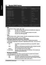
...p.m. is calculated based on the 24-hour military-time clock. IDE Channel 0 Master/Slave; Manual User can use one of three methods: Auto Allows BIOS to automatically detect IDE devices during POST(default) None Select this if no IDE devices are used and the system will skip the automatic detection... the month) 1999 to Sat. IDE Channel 1 Master/Slave IDE HDD Auto-Detection Press "Enter" to set the access mode for the hard drive. Jan. GA-K8N51GMF-9 Motherboard - 32 - Day The day, from 1 to 31 (or the maximum allowed in the month) Year The year, from Sun to Dec. IDE...
...p.m. is calculated based on the 24-hour military-time clock. IDE Channel 0 Master/Slave; Manual User can use one of three methods: Auto Allows BIOS to automatically detect IDE devices during POST(default) None Select this if no IDE devices are used and the system will skip the automatic detection... the month) 1999 to Sat. IDE Channel 1 Master/Slave IDE HDD Auto-Detection Press "Enter" to set the access mode for the hard drive. Jan. GA-K8N51GMF-9 Motherboard - 32 - Day The day, from 1 to 31 (or the maximum allowed in the month) Year The year, from Sun to Dec. IDE...

User Manual
Page 33
...Number of heads Precomp Write precomp Landing Zone Landing zone Sector Number of sectors Drive A The category identifies the types of the BIOS. Extended Memory The BIOS determines how much extended memory is the amount of the base memory is typically 512K for systems with 512K memory installed on the... the memory size that may be detected and you will determine the amount of currently installed hard drive. Base Memory The POST of the BIOS will be prompted. The value of memory located above 1 MB in the computer. No Errors The system boot will not stop for all...
...Number of heads Precomp Write precomp Landing Zone Landing zone Sector Number of sectors Drive A The category identifies the types of the BIOS. Extended Memory The BIOS determines how much extended memory is the amount of the base memory is typically 512K for systems with 512K memory installed on the... the memory size that may be detected and you will determine the amount of currently installed hard drive. Base Memory The POST of the BIOS will be prompted. The value of memory located above 1 MB in the computer. No Errors The system boot will not stop for all...
User Manual
Page 34
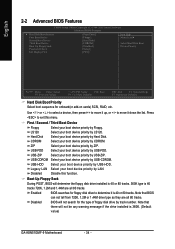
USB-HDD Select your boot device priority by CDROM. Disabled BIOS will not be any warning message if the drive installed is 360K. (Default value) GA-K8N51GMF-9 Motherboard - 34 - CDROM Select your boot device priority by USB-HDD. ZIP Select your boot device priority by ...USB-FDD. USB-FDD Select your boot device priority by ZIP. Legacy LAN Select your boot device priority by LS120. Enabled BIOS searches for floppy...
USB-HDD Select your boot device priority by CDROM. Disabled BIOS will not be any warning message if the drive installed is 360K. (Default value) GA-K8N51GMF-9 Motherboard - 34 - CDROM Select your boot device priority by USB-HDD. ZIP Select your boot device priority by ...USB-FDD. USB-FDD Select your boot device priority by ZIP. Legacy LAN Select your boot device priority by LS120. Enabled BIOS searches for floppy...

User Manual
Page 35
... to select the first initiation of the monitor display from which card when you install a PCI card and a PCI Express VGA card on the motherboard. BIOS Setup The system will boot, but access to Setup will be denied if the correct password is not entered at the prompt. (Default value) Init...
... to select the first initiation of the monitor display from which card when you install a PCI card and a PCI Express VGA card on the motherboard. BIOS Setup The system will boot, but access to Setup will be denied if the correct password is not entered at the prompt. (Default value) Init...

User Manual
Page 37
...V1.1+V2.0 Enable USB 1.1 and USB 2.0 controllers. (Default Value) V1.1 Disabled Enable only USB 1.1 controller Disable onchip USB support. BIOS Setup Disabled Disable this function. (Default value) On-Chip IDE Channel0 Enabled Disabled Enable onboard 1st channel IDE port. (Default value) Disable.... Serial-ATA-II 2 Enabled Enable Serial-ATAII 2 support. (Default Value) Disabled Disable Serial-ATAII 2 support. IDE1 Conductor Cable Auto BIOS autodetects IDE1 conductor cable. (Default Value) ATA66/100/133 Set IDE1 Conductor Cable to ATA33. (Please make sure your IDE device and...
...V1.1+V2.0 Enable USB 1.1 and USB 2.0 controllers. (Default Value) V1.1 Disabled Enable only USB 1.1 controller Disable onchip USB support. BIOS Setup Disabled Disable this function. (Default value) On-Chip IDE Channel0 Enabled Disabled Enable onboard 1st channel IDE port. (Default value) Disable.... Serial-ATA-II 2 Enabled Enable Serial-ATAII 2 support. (Default Value) Disabled Disable Serial-ATAII 2 support. IDE1 Conductor Cable Auto BIOS autodetects IDE1 conductor cable. (Default Value) ATA66/100/133 Set IDE1 Conductor Cable to ATA33. (Please make sure your IDE device and...
User Manual
Page 38
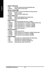
...278/IRQ5. 3BC/IRQ7 Enable onboard LPT port and address is 2E8/IRQ3. ECP Using Parallel port as ECP and EPP mode. GA-K8N51GMF-9 Motherboard - 38 - Onboard LAN Boot ROM This function decide whether to invoke the boot ROM of the onboard LAN chip. Disable...value) Onboard 1394 Function Enabled Enable onboard IEEE1394 function.(Default value) Disabled Disable onboard IEEE1394 function. Onboard Serial Port 1 Auto 3F8/IRQ4 BIOS will automatically setup the port 1 address. English Onboard LAN Function Auto Auto-detect onboard LAN chip function.(Default value) Disabled Disable onboard ...
...278/IRQ5. 3BC/IRQ7 Enable onboard LPT port and address is 2E8/IRQ3. ECP Using Parallel port as ECP and EPP mode. GA-K8N51GMF-9 Motherboard - 38 - Onboard LAN Boot ROM This function decide whether to invoke the boot ROM of the onboard LAN chip. Disable...value) Onboard 1394 Function Enabled Enable onboard IEEE1394 function.(Default value) Disabled Disable onboard IEEE1394 function. Onboard Serial Port 1 Auto 3F8/IRQ4 BIOS will automatically setup the port 1 address. English Onboard LAN Function Auto Auto-detect onboard LAN chip function.(Default value) Disabled Disable onboard ...

User Manual
Page 39
... function. If Power-On by Alarm x Day of Month Alarm : Everyday, 1~31 Time (hh: mm: ss) Alarm : (0~23) : (0~59) : (0~59) - 39 - Disabled Disable this function. BIOS Setup English 2-4 Power Management Setup CMOS Setup Utility-Copyright (C) 1984-2005 Award Software Power Management Setup ACPI Suspend Type Soft-Off by Power button PME...
... function. If Power-On by Alarm x Day of Month Alarm : Everyday, 1~31 Time (hh: mm: ss) Alarm : (0~23) : (0~59) : (0~59) - 39 - Disabled Disable this function. BIOS Setup English 2-4 Power Management Setup CMOS Setup Utility-Copyright (C) 1984-2005 Award Software Power Management Setup ACPI Suspend Type Soft-Off by Power button PME...

User Manual
Page 41
BIOS Setup Auto assign IRQ to PCI 2. (Default value) Set IRQ 3,4,5,7,9,10,11,12,14,15 to PCI 1. English 2-5 PnP/PCI Configurations CMOS Setup Utility-Copyright (C) ...
BIOS Setup Auto assign IRQ to PCI 2. (Default value) Set IRQ 3,4,5,7,9,10,11,12,14,15 to PCI 1. English 2-5 PnP/PCI Configurations CMOS Setup Utility-Copyright (C) ...

User Manual
Page 43
.... Auto Set Robust Graphics Booster to Auto. (Default value) Fast Set Robust Graphics Booster to get higher performance. Turbo Set Robust Graphics Booster to 300MHz. BIOS Setup CPU Frequency 200.0~300.0MHz Set CPU Frequency from 100MHz to 145MHz. For power end-user use only. PCIE Clock 100~145MHz Set PCIE...
.... Auto Set Robust Graphics Booster to Auto. (Default value) Fast Set Robust Graphics Booster to get higher performance. Turbo Set Robust Graphics Booster to 300MHz. BIOS Setup CPU Frequency 200.0~300.0MHz Set CPU Frequency from 100MHz to 145MHz. For power end-user use only. PCIE Clock 100~145MHz Set PCIE...

User Manual
Page 44
GA-K8N51GMF-9 Motherboard - 44 - English 2-8 Load Fail-Safe Defaults CMOS Setup Utility-Copyright (C) 1984-2005 Award Software ` Standard CMOS Features ` Advanced BIOS Features ` Integrated Peripherals ` Power Management Setup ` PnP/PCI Configurations ` PC Health Status ` Frequency/... allow minimum system performance. 2-9 Load Optimized Defaults CMOS Setup Utility-Copyright (C) 1984-2005 Award Software ` Standard CMOS Features ` Advanced BIOS Features ` Integrated Peripherals ` Power Management Setup ` PnP/PCI Configurations ` PC Health Status ` Frequency/Voltage Control Esc: Quit F8:...
GA-K8N51GMF-9 Motherboard - 44 - English 2-8 Load Fail-Safe Defaults CMOS Setup Utility-Copyright (C) 1984-2005 Award Software ` Standard CMOS Features ` Advanced BIOS Features ` Integrated Peripherals ` Power Management Setup ` PnP/PCI Configurations ` PC Health Status ` Frequency/... allow minimum system performance. 2-9 Load Optimized Defaults CMOS Setup Utility-Copyright (C) 1984-2005 Award Software ` Standard CMOS Features ` Advanced BIOS Features ` Integrated Peripherals ` Power Management Setup ` PnP/PCI Configurations ` PC Health Status ` Frequency/Voltage Control Esc: Quit F8:...


