User Manual
Page 4
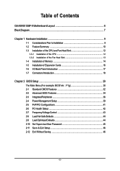
...1-3-1 Installation of the CPU 12 1-3-2 Installation of the Fan Heat Sink 13 1-4 Installation of Memory 14 1-5 Installation of Expansion Cards 16 1-6 I/O Back Panel Introduction 17 1-7 Connectors Introduction 18 Chapter 2 BIOS Setup 29 The Main Menu (For example: BIOS Ver. : F1g 30 2-1 Standard CMOS Features 32 2-2 Advanced BIOS Features 34 2-3 IntegratedPeripherals 36 2-4 Power Management Setup 39 2-5 PnP/PCI Configurations 41 2-6 PC Health Status 42 2-7 Frequency/Voltage Control 43 2-8 Load Fail-Safe Defaults 44 2-9 Load Optimized Defaults 44 2-10 Set Supervisor/User Password...
...1-3-1 Installation of the CPU 12 1-3-2 Installation of the Fan Heat Sink 13 1-4 Installation of Memory 14 1-5 Installation of Expansion Cards 16 1-6 I/O Back Panel Introduction 17 1-7 Connectors Introduction 18 Chapter 2 BIOS Setup 29 The Main Menu (For example: BIOS Ver. : F1g 30 2-1 Standard CMOS Features 32 2-2 Advanced BIOS Features 34 2-3 IntegratedPeripherals 36 2-4 Power Management Setup 39 2-5 PnP/PCI Configurations 41 2-6 PC Health Status 42 2-7 Frequency/Voltage Control 43 2-8 Load Fail-Safe Defaults 44 2-9 Load Optimized Defaults 44 2-10 Set Supervisor/User Password...
User Manual
Page 10
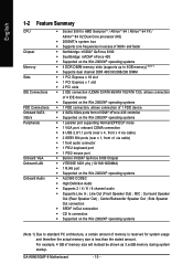
... Win 2000/XP operating systems Š ALC880 CODEC Š High Definition Audio Š Supports 2 / 4 / 6 / 8 channel audio Š Supports Line In ; GA-K8N51GMF-9 Motherboard - 10 - For example, 4 GB of memory is reserved for system usage and therefore the actual memory size is less than the stated amount. Center/Subwoofer Speaker Out ; MIC ; Line Out (Front Speaker Out) ; English 1-2 Feature Summary CPU Chipset Memory Slots IDE Connections FDD Connections Onboard SATA 3Gb/s Peripherals Onboard VGA Onboard LAN Onboard Audio Š Socket 939 for AMD...
... Win 2000/XP operating systems Š ALC880 CODEC Š High Definition Audio Š Supports 2 / 4 / 6 / 8 channel audio Š Supports Line In ; GA-K8N51GMF-9 Motherboard - 10 - For example, 4 GB of memory is reserved for system usage and therefore the actual memory size is less than the stated amount. Center/Subwoofer Speaker Out ; MIC ; Line Out (Front Speaker Out) ; English 1-2 Feature Summary CPU Chipset Memory Slots IDE Connections FDD Connections Onboard SATA 3Gb/s Peripherals Onboard VGA Onboard LAN Onboard Audio Š Socket 939 for AMD...
User Manual
Page 11
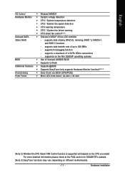
... - Hardware Installation supported on different motherboards. - 11 - supports data striping (RAID 0), mirroring (RAID 1), RAID0+1, and RAID 5 functions - supports hot plugging function - supports data transfer rate of up to 300 MB/s - English I/O Control Hardware Monitor Onboard SATA 3Gb/s RAID BIOS Additional Features Overclocking Form Factor Š Winbond W83627 Š System voltage detection Š CPU / System temperature detection Š CPU / System fan speed detection Š CPU warning temperature Š CPU / System fan failure warning Š CPU smart fan control(Note...
... - Hardware Installation supported on different motherboards. - 11 - supports data striping (RAID 0), mirroring (RAID 1), RAID0+1, and RAID 5 functions - supports hot plugging function - supports data transfer rate of up to 300 MB/s - English I/O Control Hardware Monitor Onboard SATA 3Gb/s RAID BIOS Additional Features Overclocking Form Factor Š Winbond W83627 Š System voltage detection Š CPU / System temperature detection Š CPU / System fan speed detection Š CPU warning temperature Š CPU / System fan failure warning Š CPU smart fan control(Note...
User Manual
Page 21
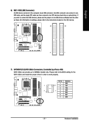
... the instructions located on one IDE cable, and the single IDE cable can then connect to 300MB/s transfer rate. One IDE connector can provide up to two IDE devices (hard drive or optical drive). Definition 1 GND 1 7 2 TXP 3 TXN 7 1 4 GND 5 RXN 6 RXP 7 GND - 21 - Hardware Installation English 6) IDE1 / IDE2 (IDE Connector) An IDE device connects to work properly. If you wish to connect two IDE devices, please set the jumper on the IDE device). 40 39 2 1 7) SATAII0/1/2/3 (SATA 3Gb/s Connectors, Controlled by...
... the instructions located on one IDE cable, and the single IDE cable can then connect to 300MB/s transfer rate. One IDE connector can provide up to two IDE devices (hard drive or optical drive). Definition 1 GND 1 7 2 TXP 3 TXN 7 1 4 GND 5 RXN 6 RXP 7 GND - 21 - Hardware Installation English 6) IDE1 / IDE2 (IDE Connector) An IDE device connects to work properly. If you wish to connect two IDE devices, please set the jumper on the IDE device). 40 39 2 1 7) SATAII0/1/2/3 (SATA 3Gb/s Connectors, Controlled by...
User Manual
Page 22
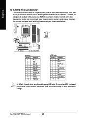
... and connector will make the audio device unable to support HD Audio. Definition 1 MIC 2 GND 3 MIC Power 4 NC 5 Line Out (R) 6 NC 7 NC 8 No Pin 9 Line Out (L) 10 NC By default, the audio driver is configured to work or even damage it. Check the pin assignments carefully while you wish to use the front audio function, connect the front panel audio module to the instructions on Page 74 about the software settings. GA-K8N51GMF-9 Motherboard...
... and connector will make the audio device unable to support HD Audio. Definition 1 MIC 2 GND 3 MIC Power 4 NC 5 Line Out (R) 6 NC 7 NC 8 No Pin 9 Line Out (L) 10 NC By default, the audio driver is configured to work or even damage it. Check the pin assignments carefully while you wish to use the front audio function, connect the front panel audio module to the instructions on Page 74 about the software settings. GA-K8N51GMF-9 Motherboard...
User Manual
Page 23
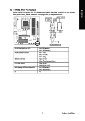
...LED/ Power/ Sleep LED Speaker Connector Power Switch MSG+ MSG- Hardware Installation RESRES+ NC HD (IDE Hard Disk Active LED) SPEAK (Speaker Connector) RES (Reset Switch) PW (Power Switch) MSG (Message LED/Power/Sleep LED) NC Reset Switch IDE Hard Disk Active LED Pin 1: LED anode(+) Pin 2: LED cathode(-) Pin 1: Power Pin 2- Pin 3: NC Pin 4: Data(-) Open: Normal Close: Reset Hardware System Open: Normal Close: Power On/Off Pin 1: LED anode(+) Pin 2: LED cathode(-) NC - 23 - PW+ PWSPEAK+ SPEAK- 2 20 1 19 HD+ HD- English 9) F_PANEL (Front Panel Jumper) Please connect the power...
...LED/ Power/ Sleep LED Speaker Connector Power Switch MSG+ MSG- Hardware Installation RESRES+ NC HD (IDE Hard Disk Active LED) SPEAK (Speaker Connector) RES (Reset Switch) PW (Power Switch) MSG (Message LED/Power/Sleep LED) NC Reset Switch IDE Hard Disk Active LED Pin 1: LED anode(+) Pin 2: LED cathode(-) Pin 1: Power Pin 2- Pin 3: NC Pin 4: Data(-) Open: Normal Close: Reset Hardware System Open: Normal Close: Power On/Off Pin 1: LED anode(+) Pin 2: LED cathode(-) NC - 23 - PW+ PWSPEAK+ SPEAK- 2 20 1 19 HD+ HD- English 9) F_PANEL (Front Panel Jumper) Please connect the power...
User Manual
Page 27
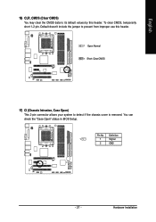
English 16) CLR_CMOS (Clear CMOS) You may clear the CMOS data to detect if the chassis cover is removed. Definition 1 1 Signal 2 GND - 27 - Pin No. Default doesn't include the jumper to prevent from improper use this header. 1 Open: Normal 1 Short: Clear CMOS 17) CI (Chassis Intrusion, Case Open) This 2-pin connector allows your system to its default values by this header. Hardware Installation To clear CMOS, temporarily short 1-2 pin. You can check the "Case Open" status in BIOS Setup.
English 16) CLR_CMOS (Clear CMOS) You may clear the CMOS data to detect if the chassis cover is removed. Definition 1 1 Signal 2 GND - 27 - Pin No. Default doesn't include the jumper to prevent from improper use this header. 1 Open: Normal 1 Short: Clear CMOS 17) CI (Chassis Intrusion, Case Open) This 2-pin connector allows your system to its default values by this header. Hardware Installation To clear CMOS, temporarily short 1-2 pin. You can check the "Case Open" status in BIOS Setup.

User Manual
Page 30
... as figure below) will appear on the screen. CMOS Setup Utility-Copyright (C) 1984-2005 Award Software ` Standard CMOS Features ` Advanced BIOS Features ` Integrated Peripherals ` Power Management Setup ` PnP/PCI Configurations ` PC Health Status ` Frequency/Voltage Control Esc: Quit F8: Q-Flash Load Fail-Safe Defaults Load Optimized Defaults Set Supervisor Password Set User Password Save & Exit Setup Exit Without Saving KLJI: Select Item F10: Save & Exit Setup Time, Date, Hard Disk Type... English The BIOS Setup menus described in this chapter are for reference...
... as figure below) will appear on the screen. CMOS Setup Utility-Copyright (C) 1984-2005 Award Software ` Standard CMOS Features ` Advanced BIOS Features ` Integrated Peripherals ` Power Management Setup ` PnP/PCI Configurations ` PC Health Status ` Frequency/Voltage Control Esc: Quit F8: Q-Flash Load Fail-Safe Defaults Load Optimized Defaults Set Supervisor Password Set User Password Save & Exit Setup Exit Without Saving KLJI: Select Item F10: Save & Exit Setup Time, Date, Hard Disk Type... English The BIOS Setup menus described in this chapter are for reference...
User Manual
Page 32
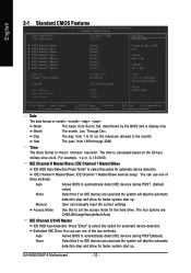
... hard drive. to Sat. You can use one of the two methods: Auto Allows BIOS to automatically detect IDE devices during POST. (Default value) None Select this to select this option for automatic device detection. Access Mode Use this if no IDE devices are : CHS/LBA/Large/Auto(default:Auto) IDE Channel 2/3/4/5 Master IDE HDD Auto-Detection Press "Enter" to Sat, determined by the BIOS and is 13:00:00. Extended IDE Drive You can manually input the correct settings. GA-K8N51GMF-9 Motherboard...
... hard drive. to Sat. You can use one of the two methods: Auto Allows BIOS to automatically detect IDE devices during POST. (Default value) None Select this to select this option for automatic device detection. Access Mode Use this if no IDE devices are : CHS/LBA/Large/Auto(default:Auto) IDE Channel 2/3/4/5 Master IDE HDD Auto-Detection Press "Enter" to Sat, determined by the BIOS and is 13:00:00. Extended IDE Drive You can manually input the correct settings. GA-K8N51GMF-9 Motherboard...
User Manual
Page 34
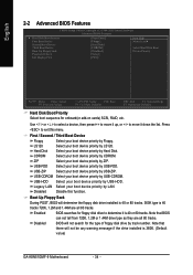
... BIOS Features CMOS Setup Utility-Copyright (C) 1984-2005 Award Software Advanced BIOS Features ` Hard Disk Boot Priority First Boot Device Second Boot Device Third Boot Device Boot Up Floppy Seek Password Check Init Display First [Press Enter] [Floppy] [Hard Disk] [CDROM] [Disabled] [Setup] [PEG] Item Help Menu Level` Select Hard Disk Boot Device Priority KLJI: Move Enter: Select F5: Previous Values +/-/PU/PD: Value F10: Save F6: Fail-Safe Defaults ESC: Exit F1: General Help F7: Optimized Defaults Hard Disk Boot Priority Select boot sequence for the type of floppy disk drive...
... BIOS Features CMOS Setup Utility-Copyright (C) 1984-2005 Award Software Advanced BIOS Features ` Hard Disk Boot Priority First Boot Device Second Boot Device Third Boot Device Boot Up Floppy Seek Password Check Init Display First [Press Enter] [Floppy] [Hard Disk] [CDROM] [Disabled] [Setup] [PEG] Item Help Menu Level` Select Hard Disk Boot Device Priority KLJI: Move Enter: Select F5: Previous Values +/-/PU/PD: Value F10: Save F6: Fail-Safe Defaults ESC: Exit F1: General Help F7: Optimized Defaults Hard Disk Boot Priority Select boot sequence for the type of floppy disk drive...
User Manual
Page 42
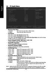
...Case Open Status Disabled Don't reset case open status. (Default value) Enabled Case Opened Clear case open status and set to CMOS, and then your computer will restart. GA-K8N51GMF-9 Motherboard - 42 - System/CPU Temperature Detect system/CPU temperature automatically. CPU Smart FAN Control (Note) Disabled Disable this function. (Default value) Enabled When this function. (Default value) System/CPU FAN Stop Warning Disabled Disable System/CPU fan stop warning function. (Default value) Enabled Enable System/CPU fan stop warning function. Current Voltage(V) VCORE / DDR Power...
...Case Open Status Disabled Don't reset case open status. (Default value) Enabled Case Opened Clear case open status and set to CMOS, and then your computer will restart. GA-K8N51GMF-9 Motherboard - 42 - System/CPU Temperature Detect system/CPU temperature automatically. CPU Smart FAN Control (Note) Disabled Disable this function. (Default value) Enabled When this function. (Default value) System/CPU FAN Stop Warning Disabled Disable System/CPU fan stop warning function. (Default value) Enabled Enable System/CPU fan stop warning function. Current Voltage(V) VCORE / DDR Power...
User Manual
Page 45
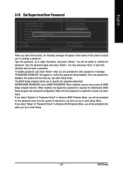
... boot and you to specify two separate passwords: SUPERVISOR PASSWORD and a USER PASSWORD. A message "PASSWORD DISABLED" will appear to eight characters, and press . Type the password, up to confirm the password being disabled. English 2-10 Set Supervisor/User Password CMOS Setup Utility-Copyright (C) 1984-2005 Award Software ` Standard CMOS Features ` Advanced BIOS Features ` Integrated Peripherals ` Power Management Setup ` PnP/PCI ConfiguratioEnsnter Password: ` PC Health Status ` Frequency/Voltage Control Load Fail-Safe Defaults Load Optimized Defaults Set Supervisor...
... boot and you to specify two separate passwords: SUPERVISOR PASSWORD and a USER PASSWORD. A message "PASSWORD DISABLED" will appear to eight characters, and press . Type the password, up to confirm the password being disabled. English 2-10 Set Supervisor/User Password CMOS Setup Utility-Copyright (C) 1984-2005 Award Software ` Standard CMOS Features ` Advanced BIOS Features ` Integrated Peripherals ` Power Management Setup ` PnP/PCI ConfiguratioEnsnter Password: ` PC Health Status ` Frequency/Voltage Control Load Fail-Safe Defaults Load Optimized Defaults Set Supervisor...
User Manual
Page 52
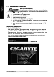
... access to use the Xpress Recovery 1. Execute Restore Utility 3. Set Password 5. Must be used to NTFS format. When the boot partition is Xpress Recovery ? Boot from CD:" appears, press any key to the IDE1 Master 3. When "Boot from CD-ROM (BMP Mode) Enter the BIOS menu, select "Advanced BIOS Feature" and set as the boot partition. Remove Backup Image 4. GIGABYTE Technology CO. , Ltd. 1. Allows installation of the screen. If the hard drive is a utility used with an IDE hard disk supporting HPA 5. Supports FAT16...
... access to use the Xpress Recovery 1. Execute Restore Utility 3. Set Password 5. Must be used to NTFS format. When the boot partition is Xpress Recovery ? Boot from CD:" appears, press any key to the IDE1 Master 3. When "Boot from CD-ROM (BMP Mode) Enter the BIOS menu, select "Advanced BIOS Feature" and set as the boot partition. Remove Backup Image 4. GIGABYTE Technology CO. , Ltd. 1. Allows installation of the screen. If the hard drive is a utility used with an IDE hard disk supporting HPA 5. Supports FAT16...
User Manual
Page 56
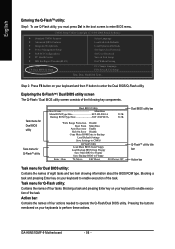
... Enter key on your keyboard to enter the Dual BIOS/Q-Flash utility. CMOS Setup Utility-Copyright (C) 1984-2004 Award Software Standard CMOS Features Advanced BIOS Features Integrated Peripherals Power Management Setup PnP/PCI Configurations PC Health Status MB Intelligent Tweaker(M.I.T.) ESC: Quit F8: Dual BIOS/Q-Flash Select Language Load Fail-Safe Defaults Load Optimized Defaults Set Supervisor Password Set User Password Save & Exit Setup Exit Without Saving F3: Change Language F10: Save & Exit Setup Time, Date, Hard Disk Type... Exploring the Q-FlashTM / Dual BIOS utility screen...
... Enter key on your keyboard to enter the Dual BIOS/Q-Flash utility. CMOS Setup Utility-Copyright (C) 1984-2004 Award Software Standard CMOS Features Advanced BIOS Features Integrated Peripherals Power Management Setup PnP/PCI Configurations PC Health Status MB Intelligent Tweaker(M.I.T.) ESC: Quit F8: Dual BIOS/Q-Flash Select Language Load Fail-Safe Defaults Load Optimized Defaults Set Supervisor Password Set User Password Save & Exit Setup Exit Without Saving F3: Change Language F10: Save & Exit Setup Time, Date, Hard Disk Type... Exploring the Q-FlashTM / Dual BIOS utility screen...
User Manual
Page 58
... keys to return to enter SETUP / Dual BIOS / Q-Flash / F9 For Xpress Recovery 09/23/2003-i875P-6A79BG03C-00 GA-K8N51GMF-9 Motherboard - 58 - English 3. Pass !! Dual BIOS Utility Boot From Main Bios Main ROM Type/Size SST 49LF003A Backup ROM Type/Size SST 49LF003A 512K 512K Wide Range Protection Disable Boot From Main Bios !A! Press Esc and then Y button to Floppy Enter : Run :Move ESC:Reset F10:Power Off After system reboots, you may find the BIOS version on your boot screen becomes the one you flashed. Award...
... keys to return to enter SETUP / Dual BIOS / Q-Flash / F9 For Xpress Recovery 09/23/2003-i875P-6A79BG03C-00 GA-K8N51GMF-9 Motherboard - 58 - English 3. Pass !! Dual BIOS Utility Boot From Main Bios Main ROM Type/Size SST 49LF003A Backup ROM Type/Size SST 49LF003A 512K 512K Wide Range Protection Disable Boot From Main Bios !A! Press Esc and then Y button to Floppy Enter : Run :Move ESC:Reset F10:Power Off After system reboots, you may find the BIOS version on your boot screen becomes the one you flashed. Award...
User Manual
Page 59
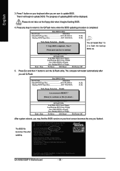
... Load Fail-Safe Defaults Integrated Peripherals Load Optimized Defaults Power Management Setup Save to update BIOS using the Q-FlashTM utility. Part Two: Updating BIOS with Q-FlashTM Utility on your keyboard to load BIOS Fail-Safe Defaults. This part guides users of single-BIOS motherboards how to CMOS and EXIT (SYe/tNS)u?pYervisor Password PnP/PCI Configurations Set User Password PC Health Status Save & Exit Setup MB Intelligent Tweaker(M.I.T.) Exit Without Saving ESC: Quit F8: Dual BIOS/Q-Flash F3: Change Language F10: Save & Exit Setup Time, Date, Hard Disk Type...
... Load Fail-Safe Defaults Integrated Peripherals Load Optimized Defaults Power Management Setup Save to update BIOS using the Q-FlashTM utility. Part Two: Updating BIOS with Q-FlashTM Utility on your keyboard to load BIOS Fail-Safe Defaults. This part guides users of single-BIOS motherboards how to CMOS and EXIT (SYe/tNS)u?pYervisor Password PnP/PCI Configurations Set User Password PC Health Status Save & Exit Setup MB Intelligent Tweaker(M.I.T.) Exit Without Saving ESC: Quit F8: Dual BIOS/Q-Flash F3: Change Language F10: Save & Exit Setup Time, Date, Hard Disk Type...
User Manual
Page 62
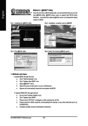
... you use the new @BIOS utility. @BIOS allows users to download the latest version of BIOS. Select the exact model name on your motherboard. II. Click "Update New BIOS". d. c. Installing the @BIOS utility Fig 2. Installation complete and run @BIOS Select @BIOS item. Click "Internet Update" icon. Please search for BIOS unzip file, downloading from internet or any other methods (such as: 51GMF9.D2). GA-K8N51GMF-9 Motherboard - 62 - System will automatically download and update the BIOS. Click "Update New BIOS" icon...
... you use the new @BIOS utility. @BIOS allows users to download the latest version of BIOS. Select the exact model name on your motherboard. II. Click "Update New BIOS". d. c. Installing the @BIOS utility Fig 2. Installation complete and run @BIOS Select @BIOS item. Click "Internet Update" icon. Please search for BIOS unzip file, downloading from internet or any other methods (such as: 51GMF9.D2). GA-K8N51GMF-9 Motherboard - 62 - System will automatically download and update the BIOS. Click "Update New BIOS" icon...

User Manual
Page 65
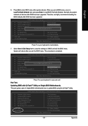
... SATA. 3) Enter the motherboard BIOS and locate RAID setup (Please refer to the section on the motherboard ie. Press F10 to select Silicon Image). 5) Complete driver installation. 6) Complete RAID utility installation. MediaShield IDE ROM BIOS 6.21 Copyright (C) 2005 NVIDIA Corp. Define a New Array window appears (as part of the array. More information on steps 4 and 5 is recommended that the hard drives used are of similar make part of the system POST and boot process...
... SATA. 3) Enter the motherboard BIOS and locate RAID setup (Please refer to the section on the motherboard ie. Press F10 to select Silicon Image). 5) Complete driver installation. 6) Complete RAID utility installation. MediaShield IDE ROM BIOS 6.21 Copyright (C) 2005 NVIDIA Corp. Define a New Array window appears (as part of the array. More information on steps 4 and 5 is recommended that the hard drives used are of similar make part of the system POST and boot process...
User Manual
Page 69
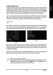
... Windows setup process. Follow the on-screen instructions to complete the installation. (Each time you add a new hard drive to a RAID array, the RAID driver will then automatically zip and transfer this floppy disk. Use an alternative system and insert the GIGABYTE motherboard driver CD-ROM. Prepare a startup disk that hard drive. Once at the A:\> prompt, change to install the RAID drivers. Press ENTER after each command (Fig.1): cd bootdrv menu Step 2: When the controller menu (Fig.2) appears, remove...
... Windows setup process. Follow the on-screen instructions to complete the installation. (Each time you add a new hard drive to a RAID array, the RAID driver will then automatically zip and transfer this floppy disk. Use an alternative system and insert the GIGABYTE motherboard driver CD-ROM. Prepare a startup disk that hard drive. Once at the A:\> prompt, change to install the RAID drivers. Press ENTER after each command (Fig.1): cd bootdrv menu Step 2: When the controller menu (Fig.2) appears, remove...
User Manual
Page 75
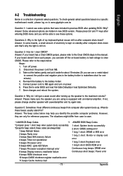
... were included in the manual. AWARD BIOS Beep Codes 1 short: System boots successfully 2 short: CMOS setting error 1 long 1 short: DRAM or M/B error 1 long 2 short: Monitor or display card error 1 long 3 short: Keyboard error 1 long 9 short: BIOS ROM error Continuous long beeps: DRAM error Continuous short beeps: Power error Appendix Answer: In some options that 's why the light is equipped with power/amplifier and try again later. Please refer to the maximum volume? Re-insert the battery to MB again and turn on -board battery to leak voltage to case. Connect power cord to the...
... were included in the manual. AWARD BIOS Beep Codes 1 short: System boots successfully 2 short: CMOS setting error 1 long 1 short: DRAM or M/B error 1 long 2 short: Monitor or display card error 1 long 3 short: Keyboard error 1 long 9 short: BIOS ROM error Continuous long beeps: DRAM error Continuous short beeps: Power error Appendix Answer: In some options that 's why the light is equipped with power/amplifier and try again later. Please refer to the maximum volume? Re-insert the battery to MB again and turn on -board battery to leak voltage to case. Connect power cord to the...


