Manual
Page 3
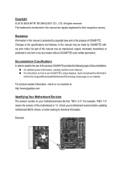
... use GIGABYTE's unique features, read or download the information on/from the Support&Downloads\Motherboard\Technology Guide page on your motherboard revision before updating motherboard BIOS, drivers, or when looking for technical information. The trademarks mentioned in this product, GIGABYTE provides the following types of documentations: For detailed product information, carefully read the User's Manual. For instructions on how to their respective owners. No part of this manual...
... use GIGABYTE's unique features, read or download the information on/from the Support&Downloads\Motherboard\Technology Guide page on your motherboard revision before updating motherboard BIOS, drivers, or when looking for technical information. The trademarks mentioned in this product, GIGABYTE provides the following types of documentations: For detailed product information, carefully read the User's Manual. For instructions on how to their respective owners. No part of this manual...

Manual
Page 4
Table of Contents GA-G41M-Combo Motherboard Layout 5 Chapter 1 Hardware Installation 6 1-1 Installation Precautions 6 1-2 Product Specifications 7 1-3 Installing the CPU and CPU Cooler 9 1-3-1 Installing the CPU...9 1-4 Installing the Memory 10 1-4-1 Dual Channel Memory Configuration 10 1-5 Installing an Expansion Card 10 1-6 Back Panel Connectors 11 1-7 Internal Connectors 12 Chapter 2 BIOS Setup 21 2-1 Startup Screen 21 2-2 The Main Menu 21 2-3 MB Intelligent Tweaker(M.I.T 22 2-4 Standard CMOS Features 28 2-5 Advanced BIOS Features 29 2-6 Advanced Chipset Features 31 2-7 ...
Table of Contents GA-G41M-Combo Motherboard Layout 5 Chapter 1 Hardware Installation 6 1-1 Installation Precautions 6 1-2 Product Specifications 7 1-3 Installing the CPU and CPU Cooler 9 1-3-1 Installing the CPU...9 1-4 Installing the Memory 10 1-4-1 Dual Channel Memory Configuration 10 1-5 Installing an Expansion Card 10 1-6 Back Panel Connectors 11 1-7 Internal Connectors 12 Chapter 2 BIOS Setup 21 2-1 Startup Screen 21 2-2 The Main Menu 21 2-3 MB Intelligent Tweaker(M.I.T 22 2-4 Standard CMOS Features 28 2-5 Advanced BIOS Features 29 2-6 Advanced Chipset Features 31 2-7 ...
Manual
Page 5
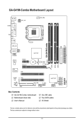
... you obtain. GA-G41M-Combo Motherboard Layout KB_MS COMA ATX_12V VGA CPU_FAN LGA775 LPT COMB R_USB USB_LAN AUDIO F_AUDIO Atheros AR8151 iTE IT8718F PCIEX1 PCIEX16 PCI1 Intel® G41 BAT B_BIOS M_BIOS CLR_CMOS DDR2_1 GA-G41M-Combo DDR3_1 DDR2_2 DDR3_2 IDE ATX CD_IN SPDIF_O CODEC PCI2 FDD SYS_FAN F_USB2 F_USB1 Intel® ICH7 SATA2_3 SATA2_2 SATA2_0 SATA2_1 Box Contents GA-G41M-Combo motherboard Motherboard driver disk User's Manual One IDE cable Two SATA cables I/O Shield...
... you obtain. GA-G41M-Combo Motherboard Layout KB_MS COMA ATX_12V VGA CPU_FAN LGA775 LPT COMB R_USB USB_LAN AUDIO F_AUDIO Atheros AR8151 iTE IT8718F PCIEX1 PCIEX16 PCI1 Intel® G41 BAT B_BIOS M_BIOS CLR_CMOS DDR2_1 GA-G41M-Combo DDR3_1 DDR2_2 DDR3_2 IDE ATX CD_IN SPDIF_O CODEC PCI2 FDD SYS_FAN F_USB2 F_USB1 Intel® ICH7 SATA2_3 SATA2_2 SATA2_0 SATA2_1 Box Contents GA-G41M-Combo motherboard Motherboard driver disk User's Manual One IDE cable Two SATA cables I/O Shield...
Manual
Page 7
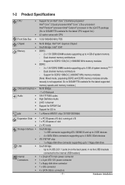
... the internal USB headers) Internal w 1 x 24-pin ATX main power connector Connectors w 1 x 4-pin ATX 12V power connector w 1 x floppy disk drive connector w 1 x IDE connector w 4 x SATA 3Gb/s connectors - 7 - Go to GIGABYTE's website for the latest supported memory speeds and memory modules.) North Bridge: - 1 x D-Sub port VIA VT1708S codec High Definition Audio 2/4/5.1-channel Support for S/PDIF Out Support for CD In 1 x Atheros AR8151 chip (10/100/1000 Mbit) Expansion Slots w 1 x PCI Express x16 slot, running at x16 1 x PCI Express...
... the internal USB headers) Internal w 1 x 24-pin ATX main power connector Connectors w 1 x 4-pin ATX 12V power connector w 1 x floppy disk drive connector w 1 x IDE connector w 4 x SATA 3Gb/s connectors - 7 - Go to GIGABYTE's website for the latest supported memory speeds and memory modules.) North Bridge: - 1 x D-Sub port VIA VT1708S codec High Definition Audio 2/4/5.1-channel Support for S/PDIF Out Support for CD In 1 x Atheros AR8151 chip (10/100/1000 Mbit) Expansion Slots w 1 x PCI Express x16 slot, running at x16 1 x PCI Express...
Manual
Page 10
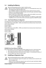
... supported. When enabling Dual Channel mode with your expansion card. • Always turn off the computer and unplug the power cord from the power outlet before installing the memory to insert the memory, switch the direction. • Populating DDR2 and DDR3 memory modules simultaneously is recommended that memory of the same capacity, brand, speed, and chips be sure to install an expansion card: • Make sure the motherboard supports the expansion card...
... supported. When enabling Dual Channel mode with your expansion card. • Always turn off the computer and unplug the power cord from the power outlet before installing the memory to insert the memory, switch the direction. • Populating DDR2 and DDR3 memory modules simultaneously is recommended that memory of the same capacity, brand, speed, and chips be sure to install an expansion card: • Make sure the motherboard supports the expansion card...
Manual
Page 14
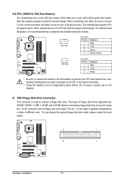
...black connector wire is used to locate pin 1 of floppy disk drives supported are not configuration jumper blocks. The types of the connector and the floppy disk drive cable. For purchasing the optional floppy disk drive cable, please contact the local dealer. 33 1 34 2 Hardware Installation - 14 - 3/4) CPU_FAN/SYS_FAN (Fan Headers) The motherboard has a 4-pin CPU fan header (CPU_FAN) and a 3-pin (SYS_FAN) system fan header. Most fan headers possess a foolproof insertion design. Before connecting a floppy disk drive, be installed inside the chassis. 1 CPU_FAN CPU_FAN: Pin No...
...black connector wire is used to locate pin 1 of floppy disk drives supported are not configuration jumper blocks. The types of the connector and the floppy disk drive cable. For purchasing the optional floppy disk drive cable, please contact the local dealer. 33 1 34 2 Hardware Installation - 14 - 3/4) CPU_FAN/SYS_FAN (Fan Headers) The motherboard has a 4-pin CPU fan header (CPU_FAN) and a 3-pin (SYS_FAN) system fan header. Most fan headers possess a foolproof insertion design. Before connecting a floppy disk drive, be installed inside the chassis. 1 CPU_FAN CPU_FAN: Pin No...

Manual
Page 18
... (2x5-pin) cable into the USB header. • Prior to installing the USB bracket, be sure to turn off your computer and unplug the power cord from your motherboard to certain expansion cards like graphics cards and sound cards. For information about connecting the S/PDIF digital audio cable, carefully read the manual for your graphics card if you wish to connect an HDMI display to the graphics card and have digital audio output from the HDMI display at...
... (2x5-pin) cable into the USB header. • Prior to installing the USB bracket, be sure to turn off your computer and unplug the power cord from your motherboard to certain expansion cards like graphics cards and sound cards. For information about connecting the S/PDIF digital audio cable, carefully read the manual for your graphics card if you wish to connect an HDMI display to the graphics card and have digital audio output from the HDMI display at...
Manual
Page 19
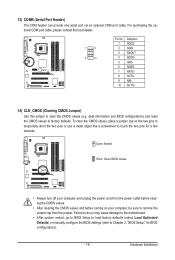
... optional COM port cable. Failure to do so may cause damage to the motherboard. • After system restart, go to BIOS Setup to load factory defaults (select Load Optimized Defaults) or manually configure the BIOS settings (refer to Chapter 2, "BIOS Setup," for a few seconds. Open: Normal Short: Clear CMOS Values • Always turn off your computer and unplug the power cord from the jumper. Hardware Installation date information and BIOS configurations) and reset the CMOS values to remove the jumper...
... optional COM port cable. Failure to do so may cause damage to the motherboard. • After system restart, go to BIOS Setup to load factory defaults (select Load Optimized Defaults) or manually configure the BIOS settings (refer to Chapter 2, "BIOS Setup," for a few seconds. Open: Normal Short: Clear CMOS Values • Always turn off your computer and unplug the power cord from the jumper. Hardware Installation date information and BIOS configurations) and reset the CMOS values to remove the jumper...
Manual
Page 21
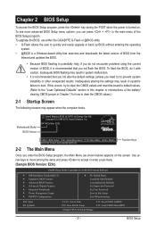
... BIOS without entering the operating system. • @BIOS is a Windows-based utility that you need to) to BIOS F12: Load CMOS from the Internet and updates the BIOS. • Because BIOS flashing is recommended that you not alter the default settings (unless you not flash the BIOS. G41M-Combo E20c . . . . : BIOS Setup : XpressRecovery2 : Boot Menu : Qflash 05/07/2010-G41-ICH7-6A79PG0FC-00 Function Keys 2-2 The Main Menu Once you do it is turned on the screen. BIOS Setup Motherboard Model BIOS Version Award...
... BIOS without entering the operating system. • @BIOS is a Windows-based utility that you need to) to BIOS F12: Load CMOS from the Internet and updates the BIOS. • Because BIOS flashing is recommended that you not alter the default settings (unless you not flash the BIOS. G41M-Combo E20c . . . . : BIOS Setup : XpressRecovery2 : Boot Menu : Qflash 05/07/2010-G41-ICH7-6A79PG0FC-00 Function Keys 2-2 The Main Menu Once you do it is turned on the screen. BIOS Setup Motherboard Model BIOS Version Award...
Manual
Page 23
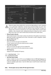
... configurations. If this feature. - 23 - mode based on your system fails to boot after overclocking, please wait for the installed CPU. Options are: Auto (default), Fast, Turbo. Fine CPU Clock Ratio (Note) Allows you to CPU, chipset, or memory and reduce the useful life of these components. CPU Frequency Displays the current operating CPU frequency. ******** Clock Chip Control Standard Clock Control CPU Host Clock Control Enables or disables the control of the graphics chip and memory. BIOS Setup The item is present only if a CPU with unlocked clock...
... configurations. If this feature. - 23 - mode based on your system fails to boot after overclocking, please wait for the installed CPU. Options are: Auto (default), Fast, Turbo. Fine CPU Clock Ratio (Note) Allows you to CPU, chipset, or memory and reduce the useful life of these components. CPU Frequency Displays the current operating CPU frequency. ******** Clock Chip Control Standard Clock Control CPU Host Clock Control Enables or disables the control of the graphics chip and memory. BIOS Setup The item is present only if a CPU with unlocked clock...
Manual
Page 27
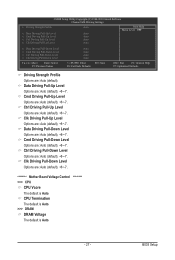
...Auto (default), +8~-7. Clk Driving Pull-Down Level Options are : Auto (default), +8~-7. BIOS Setup Cmd Driving Pull-Up Level Options are : Auto (default), +8~-7. ******** Mother Board Voltage Control CPU CPU Vcore The default is Auto. - 27 - Ctrl Driving Pull-Down Level Options are : Auto (default). CMOS Setup Utility-Copyright (C) 1984-2010 Award Software Channel A/B Driving Settings x Driving Strength Profile x Data Driving Pull-Up Level x Cmd Driving Pull-Up Level x Ctrl Driving Pull-Up Level x Clk Driving Pull-Up Level Auto Auto Auto Auto Auto Item Help Menu...
...Auto (default), +8~-7. Clk Driving Pull-Down Level Options are : Auto (default), +8~-7. BIOS Setup Cmd Driving Pull-Up Level Options are : Auto (default), +8~-7. ******** Mother Board Voltage Control CPU CPU Vcore The default is Auto. - 27 - Ctrl Driving Pull-Down Level Options are : Auto (default). CMOS Setup Utility-Copyright (C) 1984-2010 Award Software Channel A/B Driving Settings x Driving Strength Profile x Data Driving Pull-Up Level x Cmd Driving Pull-Up Level x Ctrl Driving Pull-Up Level x Clk Driving Pull-Up Level Auto Auto Auto Auto Auto Item Help Menu...
Manual
Page 29
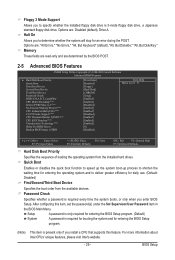
... +/-/PU/PD: Value F10: Save F6: Fail-Safe Defaults ESC: Exit F1: General Help F7: Optimized Defaults Hard Disk Boot Priority Specifies the sequence of loading the operating system from the available devices. Setup A password is only required for entering the BIOS Setup program. (Default) System A password is 3-mode floppy disk drive, a Japanese standard floppy disk drive. Floppy 3 Mode Support Allows you install a CPU that supports this item, set the password(s) under the Set Supervisor/User Password item in the BIOS Main Menu. Options are: Disabled (default), Drive A.
... +/-/PU/PD: Value F10: Save F6: Fail-Safe Defaults ESC: Exit F1: General Help F7: Optimized Defaults Hard Disk Boot Priority Specifies the sequence of loading the operating system from the available devices. Setup A password is only required for entering the BIOS Setup program. (Default) System A password is 3-mode floppy disk drive, a Japanese standard floppy disk drive. Floppy 3 Mode Support Allows you install a CPU that supports this item, set the password(s) under the Set Supervisor/User Password item in the BIOS Main Menu. Options are: Disabled (default), Drive A.
Manual
Page 30
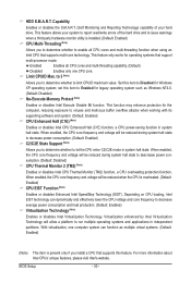
... lower the CPU voltage and core frequency to Disabled for legacy operating system such as multiple virtual systems. (Default: Enabled) (Note) This item is present only if you to determine whether to enable all CPU cores and multi-threading function when using an Intel CPU that support multi-processor mode. Capability Enables or disables the S.M.A.R.T. (Self Monitoring and Reporting Technology) capability of the hard drive and to let the CPU enter C2/C2E mode in system...
... lower the CPU voltage and core frequency to Disabled for legacy operating system such as multiple virtual systems. (Default: Enabled) (Note) This item is present only if you to determine whether to enable all CPU cores and multi-threading function when using an Intel CPU that support multi-processor mode. Capability Enables or disables the S.M.A.R.T. (Self Monitoring and Reporting Technology) capability of the hard drive and to let the CPU enter C2/C2E mode in system...
Manual
Page 31
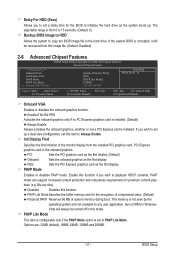
... any user application. Delay For HDD (Secs) Allows you to set a delay time for the BIOS to initialize the hard drive as the system boots up a dual view configuration, set this item to Always Enable. Aero (DWM) in Windows Vista will be turned off in this mode. The adjustable range is from this image file. (Default: Disabled) 2-6 Advanced Chipset Features CMOS Setup Utility-Copyright (C) 1984-2010 Award Software Advanced Chipset Features ** VGA Setting ** Onboard VGA Init Display First PAVP Mode...
... any user application. Delay For HDD (Secs) Allows you to set a delay time for the BIOS to initialize the hard drive as the system boots up a dual view configuration, set this item to Always Enable. Aero (DWM) in Windows Vista will be turned off in this mode. The adjustable range is from this image file. (Default: Disabled) 2-6 Advanced Chipset Features CMOS Setup Utility-Copyright (C) 1984-2010 Award Software Advanced Chipset Features ** VGA Setting ** Onboard VGA Init Display First PAVP Mode...
Manual
Page 32
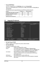
... memory No (96 MB reserved during boot) PAVP Paranoid Yes Yes Yes 2-7 Integrated Peripherals CMOS Setup Utility-Copyright (C) 1984-2010 Award Software Integrated Peripherals On-Chip Primary PCI IDE On-Chip SATA Mode x PATA IDE Set to SATA Port 0/2 Set to SATA Port 1/3 Set to Azalia Codec Onboard H/W LAN } SMART LAN Onboard LAN Boot ROM Onboard Serial Port 1 Onboard Serial Port 2 Onboard Parallel Port Parallel Port Mode USB 1.0 Controller USB 2.0 Controller USB Keyboard Support USB Mouse Support USB Storage Function [Enabled...
... memory No (96 MB reserved during boot) PAVP Paranoid Yes Yes Yes 2-7 Integrated Peripherals CMOS Setup Utility-Copyright (C) 1984-2010 Award Software Integrated Peripherals On-Chip Primary PCI IDE On-Chip SATA Mode x PATA IDE Set to SATA Port 0/2 Set to SATA Port 1/3 Set to Azalia Codec Onboard H/W LAN } SMART LAN Onboard LAN Boot ROM Onboard Serial Port 1 Onboard Serial Port 2 Onboard Parallel Port Parallel Port Mode USB 1.0 Controller USB 2.0 Controller USB Keyboard Support USB Mouse Support USB Storage Function [Enabled...
Manual
Page 33
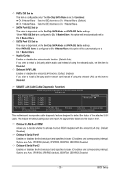
... onboard LAN chip. (Default: Disabled) Onboard Serial Port 1 Enables or disables the first serial port and specifies its base I /O address and corresponding interrupt. SMART LAN (LAN Cable Diagnostic Function) CMOS Setup Utility-Copyright (C) 1984-2010 Award Software SMART LAN Start detecting at Port..... When PATA IDE Set to is dependent on the On-Chip SATA Mode and PATA IDE Set to settings. BIOS Setup When PATA IDE Set to is set to Ch. 1 Master/Slave. Onboard LAN Boot ROM Allows you wish to install a 3rd party add-in network card instead of the attached LAN cable. PATA IDE Set...
... onboard LAN chip. (Default: Disabled) Onboard Serial Port 1 Enables or disables the first serial port and specifies its base I /O address and corresponding interrupt. SMART LAN (LAN Cable Diagnostic Function) CMOS Setup Utility-Copyright (C) 1984-2010 Award Software SMART LAN Start detecting at Port..... When PATA IDE Set to is dependent on the On-Chip SATA Mode and PATA IDE Set to settings. BIOS Setup When PATA IDE Set to is set to Ch. 1 Master/Slave. Onboard LAN Boot ROM Allows you wish to install a 3rd party add-in network card instead of the attached LAN cable. PATA IDE Set...
Manual
Page 34
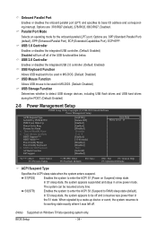
...Suspend) sleep state. USB 2.0 Controller Enables or disables the integrated USB 2.0 controller. (Default: Enabled) USB Keyboard Function Allows USB keyboard to be used in MS-DOS. (Default: Disabled) USB Mouse Function Allows USB mouse to be used in the S1 state. The system can be off and consumes less power than in MS-DOS. (Default: Disabled) USB Storage Function Determines whether to detect USB storage devices, including USB flash drives and USB hard drives during the POST. (Default: Enabled) 2-8 Power Management Setup CMOS Setup Utility-Copyright (C) 1984-2010 Award Software Power...
...Suspend) sleep state. USB 2.0 Controller Enables or disables the integrated USB 2.0 controller. (Default: Enabled) USB Keyboard Function Allows USB keyboard to be used in MS-DOS. (Default: Disabled) USB Mouse Function Allows USB mouse to be used in the S1 state. The system can be off and consumes less power than in MS-DOS. (Default: Disabled) USB Storage Function Determines whether to detect USB storage devices, including USB flash drives and USB hard drives during the POST. (Default: Enabled) 2-8 Power Management Setup CMOS Setup Utility-Copyright (C) 1984-2010 Award Software Power...
Manual
Page 35
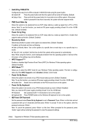
... enter suspend mode. BIOS Setup Soft-Off by PWR-BTTN Configures the way to accept. Note: To use this function, you need an ATX power supply providing at a specific time on each day or on a specific day in MS-DOS mode using this item. Password Set a password with up signal from an ACPI sleep state by a wake-up to 5 characters and then press to turn on by Keyboard is set to Enabled. (Default: 32-bit mode) Power...
... enter suspend mode. BIOS Setup Soft-Off by PWR-BTTN Configures the way to accept. Note: To use this function, you need an ATX power supply providing at a specific time on each day or on a specific day in MS-DOS mode using this item. Password Set a password with up signal from an ACPI sleep state by a wake-up to 5 characters and then press to turn on by Keyboard is set to Enabled. (Default: 32-bit mode) Power...
Manual
Page 36
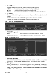
...,12,14,15 BIOS auto-assigns IRQ to the first/second PCI slot. (Default) Assigns IRQ 3,4,5,7,9,10,11,12,14,15 to the first/second PCI slot. 2-10 PC Health Status CMOS Setup Utility-Copyright (C) 1984-2010 Award Software PC Health Status Reset Case Open Status Case Opened Vcore DDR +3.3V +12V Current CPU Temperature Current CPU FAN Speed Current SYSTEM FAN Speed CPU Warning Temperature CPU FAN Fail Warning SYSTEM FAN Fail Warning CPU Smart FAN Control [Disabled] No 1.300V 1.584V...
...,12,14,15 BIOS auto-assigns IRQ to the first/second PCI slot. (Default) Assigns IRQ 3,4,5,7,9,10,11,12,14,15 to the first/second PCI slot. 2-10 PC Health Status CMOS Setup Utility-Copyright (C) 1984-2010 Award Software PC Health Status Reset Case Open Status Case Opened Vcore DDR +3.3V +12V Current CPU Temperature Current CPU FAN Speed Current SYSTEM FAN Speed CPU Warning Temperature CPU FAN Fail Warning SYSTEM FAN Fail Warning CPU Smart FAN Control [Disabled] No 1.300V 1.584V...
Manual
Page 37
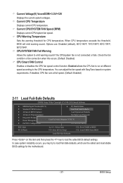
... the key to the CPU temperature. Current CPU Temperature Displays current CPU temperature. If disabled, CPU fan runs at different speed according to load the safest BIOS default settings. CPU/SYSTEM FAN Fail Warning Allows the system to load Fail-Safe defaults, which are : Disabled (default), 60oC/140oF, 70oC/158oF, 80oC/176oF, 90oC/194oF. BIOS Setup You can adjust the fan speed with EasyTune based on this occurs. (Default: Disabled) CPU Smart FAN Control Enables or disables the CPU fan speed control function. Current Voltage(V) Vcore/DDR/+3.3V/+12V Displays the...
... the key to the CPU temperature. Current CPU Temperature Displays current CPU temperature. If disabled, CPU fan runs at different speed according to load the safest BIOS default settings. CPU/SYSTEM FAN Fail Warning Allows the system to load Fail-Safe defaults, which are : Disabled (default), 60oC/140oF, 70oC/158oF, 80oC/176oF, 90oC/194oF. BIOS Setup You can adjust the fan speed with EasyTune based on this occurs. (Default: Disabled) CPU Smart FAN Control Enables or disables the CPU fan speed control function. Current Voltage(V) Vcore/DDR/+3.3V/+12V Displays the...


