Manual
Page 1
GA-G41M-Combo LGA775 socket motherboard for Intel® Core™ processor family/ Intel® Pentium® processor family/Intel® Celeron® processor family User's Manual Rev. 1302 12ME-G41MC-1302R
GA-G41M-Combo LGA775 socket motherboard for Intel® Core™ processor family/ Intel® Pentium® processor family/Intel® Celeron® processor family User's Manual Rev. 1302 12ME-G41MC-1302R
Manual
Page 2
Motherboard GA-G41M-Combo May 24, 2010 Motherboard GA-G41M-Combo May 24, 2010
Motherboard GA-G41M-Combo May 24, 2010 Motherboard GA-G41M-Combo May 24, 2010
Manual
Page 3
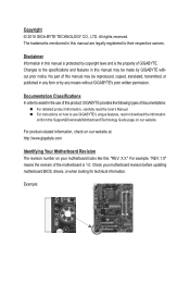
...be reproduced, copied, translated, transmitted, or published in the use of this manual may be made by GIGABYTE without GIGABYTE's prior written permission. The trademarks mentioned in this manual are legally registered to the specifications and features in this product... of documentations: For detailed product information, carefully read the User's Manual. For instructions on how to use GIGABYTE's unique features, read or download the information on/from the Support&Downloads\Motherboard\Technology Guide page on your motherboard revision before updating ...
...be reproduced, copied, translated, transmitted, or published in the use of this manual may be made by GIGABYTE without GIGABYTE's prior written permission. The trademarks mentioned in this manual are legally registered to the specifications and features in this product... of documentations: For detailed product information, carefully read the User's Manual. For instructions on how to use GIGABYTE's unique features, read or download the information on/from the Support&Downloads\Motherboard\Technology Guide page on your motherboard revision before updating ...

Manual
Page 4
Table of Contents GA-G41M-Combo Motherboard Layout 5 Chapter 1 Hardware Installation 6 1-1 Installation Precautions 6 1-2 Product Specifications 7 1-3 Installing the CPU and CPU Cooler 9 1-3-1 Installing the CPU...9 1-4 Installing the Memory 10 1-4-1 Dual Channel Memory ...
Table of Contents GA-G41M-Combo Motherboard Layout 5 Chapter 1 Hardware Installation 6 1-1 Installation Precautions 6 1-2 Product Specifications 7 1-3 Installing the CPU and CPU Cooler 9 1-3-1 Installing the CPU...9 1-4 Installing the Memory 10 1-4-1 Dual Channel Memory ...
Manual
Page 5
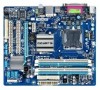
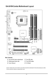
... ATX_12V VGA CPU_FAN LGA775 LPT COMB R_USB USB_LAN AUDIO F_AUDIO Atheros AR8151 iTE IT8718F PCIEX1 PCIEX16 PCI1 Intel® G41 BAT B_BIOS M_BIOS CLR_CMOS DDR2_1 GA-G41M-Combo DDR3_1 DDR2_2 DDR3_2 IDE ATX CD_IN SPDIF_O CODEC PCI2 FDD SYS_FAN F_USB2 F_USB1 Intel® ICH7 SATA2_3 SATA2_2 SATA2_0 SATA2_1 Box Contents...
... ATX_12V VGA CPU_FAN LGA775 LPT COMB R_USB USB_LAN AUDIO F_AUDIO Atheros AR8151 iTE IT8718F PCIEX1 PCIEX16 PCI1 Intel® G41 BAT B_BIOS M_BIOS CLR_CMOS DDR2_1 GA-G41M-Combo DDR3_1 DDR2_2 DDR3_2 IDE ATX CD_IN SPDIF_O CODEC PCI2 FDD SYS_FAN F_USB2 F_USB1 Intel® ICH7 SATA2_3 SATA2_2 SATA2_0 SATA2_1 Box Contents...
Manual
Page 6
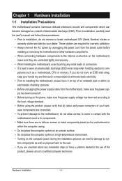
These stickers are required for warranty validation. • Always remove the AC power by your hardware components are connected. • To prevent damage to the motherboard, do not remove or break motherboard S/N (Serial Number) sticker or warranty sticker provided by unplugging the power cord from the power outlet before installing or removing the motherboard or other hardware components. • When connecting hardware components to the internal connectors on the computer power during the installation process can become damaged as a motherboard, CPU or memory. ponents such as a...
These stickers are required for warranty validation. • Always remove the AC power by your hardware components are connected. • To prevent damage to the motherboard, do not remove or break motherboard S/N (Serial Number) sticker or warranty sticker provided by unplugging the power cord from the power outlet before installing or removing the motherboard or other hardware components. • When connecting hardware components to the internal connectors on the computer power during the installation process can become damaged as a motherboard, CPU or memory. ponents such as a...
Manual
Page 7
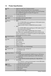
...; Core™ 2 Duo processor/ Intel® Pentium® processor/Intel® Celeron® processor in the LGA775 package (Go to GIGABYTE's website for the latest CPU support list.) L2 cache varies with CPU Front Side Bus w 1333/1066/800 MHz FSB Chipset w w ... 4 x SATA 3Gb/s connectors supporting up to 4 SATA 3Gb/s devices w iTE IT8718F chip: - 1 x floppy disk drive connector supporting up to GIGABYTE's website for the latest supported memory speeds and memory modules.) North Bridge: - 1 x D-Sub port VIA VT1708S codec High Definition Audio 2/4/5.1-channel Support ...
...; Core™ 2 Duo processor/ Intel® Pentium® processor/Intel® Celeron® processor in the LGA775 package (Go to GIGABYTE's website for the latest CPU support list.) L2 cache varies with CPU Front Side Bus w 1333/1066/800 MHz FSB Chipset w w ... 4 x SATA 3Gb/s connectors supporting up to 4 SATA 3Gb/s devices w iTE IT8718F chip: - 1 x floppy disk drive connector supporting up to GIGABYTE's website for the latest supported memory speeds and memory modules.) North Bridge: - 1 x D-Sub port VIA VT1708S codec High Definition Audio 2/4/5.1-channel Support ...
Manual
Page 8
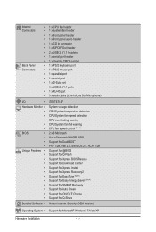
Internal Connectors Back Panel Connectors w 1 x CPU fan header w 1 x system fan header w 1 x front panel header w 1 x front panel audio header w 1 x CD In connector w 1 x S/PDIF Out header w 2 x USB 2.0/1.1 headers w 1 x serial port header w 1 x clearing CMOS jumper w 1 x PS/2 keyboard port w 1 x PS/2 mouse port w 1 x parallel port w 1 x serial port w 1 x D-Sub port w 4 x USB 2.0/1.1 ports w 1 x RJ-45 port w 3 x audio jacks (Line In/Line Out/Microphone) I/O w iTE IT8718F Hardware Monitor w w w w w w BIOS w w w w Unique ...
Internal Connectors Back Panel Connectors w 1 x CPU fan header w 1 x system fan header w 1 x front panel header w 1 x front panel audio header w 1 x CD In connector w 1 x S/PDIF Out header w 2 x USB 2.0/1.1 headers w 1 x serial port header w 1 x clearing CMOS jumper w 1 x PS/2 keyboard port w 1 x PS/2 mouse port w 1 x parallel port w 1 x serial port w 1 x D-Sub port w 4 x USB 2.0/1.1 ports w 1 x RJ-45 port w 3 x audio jacks (Line In/Line Out/Microphone) I/O w iTE IT8718F Hardware Monitor w w w w w w BIOS w w w w Unique ...
Manual
Page 9
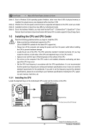
... the power cord from the power outlet before you begin to install the CPU: • Make sure that the motherboard supports the CPU. (Go to GIGABYTE's website for the latest CPU support list.) • Always turn on the computer if the CPU cooler is not recommended that the system bus frequency...
... the power cord from the power outlet before you begin to install the CPU: • Make sure that the motherboard supports the CPU. (Go to GIGABYTE's website for the latest CPU support list.) • Always turn on the computer if the CPU cooler is not recommended that the system bus frequency...
Manual
Page 10
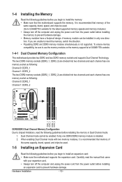
... DDR2_2 DDR2_1 DDR3_1 DDR2_2 DDR3_2 DDR3/DDR2 Dual Channel Memory Configuration: Due to use the memory modules on the memory support list at GIGABYTE's website. 1-4-1 Dual Channel Memory Configuration This motherboard provides two DDR2 and two DDR3 memory sockets and supports Dual Channel Technology. Hardware ...expansion card to prevent hardware damage. • Memory modules have a foolproof design. A memory module can be used . (Go to GIGABYTE's website for the latest supported memory speeds and memory modules.) • Always turn off the computer and unplug the power cord from...
... DDR2_2 DDR2_1 DDR3_1 DDR2_2 DDR3_2 DDR3/DDR2 Dual Channel Memory Configuration: Due to use the memory modules on the memory support list at GIGABYTE's website. 1-4-1 Dual Channel Memory Configuration This motherboard provides two DDR2 and two DDR3 memory sockets and supports Dual Channel Technology. Hardware ...expansion card to prevent hardware damage. • Memory modules have a foolproof design. A memory module can be used . (Go to GIGABYTE's website for the latest supported memory speeds and memory modules.) • Always turn off the computer and unplug the power cord from...
Manual
Page 11
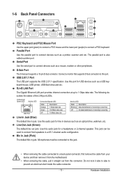
Parallel Port Use the parallel port to connect devices such as a USB keyboard/mouse, USB printer, USB flash drive and etc. Use this audio jack for line in jack. D-Sub Port The D-Sub port supports a 15-pin D-Sub connector. Mic In Jack (Pink) The default Mic in a 4/5.1-channel audio configuration. Connect a monitor that supports D-Sub connection to this jack. • When removing the cable connected to a back panel connector, first remove the cable from your device and then remove it from the motherboard. • When removing the cable, pull it side to side to connect ...
Parallel Port Use the parallel port to connect devices such as a USB keyboard/mouse, USB printer, USB flash drive and etc. Use this audio jack for line in jack. D-Sub Port The D-Sub port supports a 15-pin D-Sub connector. Mic In Jack (Pink) The default Mic in a 4/5.1-channel audio configuration. Connect a monitor that supports D-Sub connection to this jack. • When removing the cable connected to a back panel connector, first remove the cable from your device and then remove it from the motherboard. • When removing the cable, pull it side to side to connect ...
Manual
Page 12
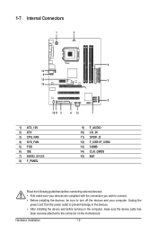
Hardware Installation - 12 - Unplug the power cord from the power outlet to prevent damage to the devices. • After installing the device and before connecting external devices: • First make sure the device cable has been securely attached to turn off the devices and your computer. 1-7 Internal Connectors 1 3 6 13 9 15 2 14 8 1011 5 4 12 7 1) ATX_12V 2) ATX 3) CPU_FAN 4) SYS_FAN 5) FDD 6) IDE 7) SATA2_0/1/2/3 8) F_PANEL 9) F_AUDIO 10) CD_IN 11) SPDIF_O 12) F_USB1/F_USB2 13) COMB 14) CLR_CMOS 15) BAT Read the following guidelines before turning on the computer,...
Hardware Installation - 12 - Unplug the power cord from the power outlet to prevent damage to the devices. • After installing the device and before connecting external devices: • First make sure the device cable has been securely attached to turn off the devices and your computer. 1-7 Internal Connectors 1 3 6 13 9 15 2 14 8 1011 5 4 12 7 1) ATX_12V 2) ATX 3) CPU_FAN 4) SYS_FAN 5) FDD 6) IDE 7) SATA2_0/1/2/3 8) F_PANEL 9) F_AUDIO 10) CD_IN 11) SPDIF_O 12) F_USB1/F_USB2 13) COMB 14) CLR_CMOS 15) BAT Read the following guidelines before turning on the computer,...
Manual
Page 13
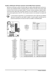
1/2) ATX_12V/ATX (2x2 12V Power Connector and 2x12 Main Power Connector) With the use of the power connector, the power supply can supply enough stable power to all devices are properly installed. Connect the power supply cable to the CPU. The 12V power connector mainly supplies power to the power connector in the correct orientation. To meet expansion requirements, it is used that can lead to an unstable or unbootable system. 3 4 1 2 ATX_12V ATX_12V: Pin No. 1 2 3 4 Definition GND GND +12V +12V 12 24 1 13 ATX ATX: Pin No. 1 2 3 4 5 6 7 8 9 10 11 12 Definition Pin No. 3....
1/2) ATX_12V/ATX (2x2 12V Power Connector and 2x12 Main Power Connector) With the use of the power connector, the power supply can supply enough stable power to all devices are properly installed. Connect the power supply cable to the CPU. The 12V power connector mainly supplies power to the power connector in the correct orientation. To meet expansion requirements, it is used that can lead to an unstable or unbootable system. 3 4 1 2 ATX_12V ATX_12V: Pin No. 1 2 3 4 Definition GND GND +12V +12V 12 24 1 13 ATX ATX: Pin No. 1 2 3 4 5 6 7 8 9 10 11 12 Definition Pin No. 3....
Manual
Page 14
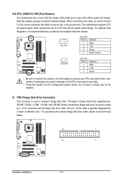
When connecting a fan cable, be sure to the CPU or the system may result in the correct orientation (the black connector wire is used to prevent your CPU and system from overheating. Overheating may hang. • These fan headers are : 360 KB, 720 KB, 1.2 MB, 1.44 MB, and 2.88 MB. The types of a CPU fan with fan speed control design. Most fan headers possess a foolproof insertion design. Before connecting a floppy disk drive, be sure to connect it is typically designated by a stripe of different color. The pin 1 of the connector and the floppy disk drive cable. For ...
When connecting a fan cable, be sure to the CPU or the system may result in the correct orientation (the black connector wire is used to prevent your CPU and system from overheating. Overheating may hang. • These fan headers are : 360 KB, 720 KB, 1.2 MB, 1.44 MB, and 2.88 MB. The types of a CPU fan with fan speed control design. Most fan headers possess a foolproof insertion design. Before connecting a floppy disk drive, be sure to connect it is typically designated by a stripe of different color. The pin 1 of the connector and the floppy disk drive cable. For ...
Manual
Page 15
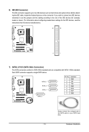
6) IDE (IDE Connector) The IDE connector supports up to SATA 3Gb/s standard and are compatible with SATA 1.5Gb/s standard. If you wish to connect two IDE devices, remember to set the jumpers and the cabling according to the role of the SATA cable to your SATA hard drive. Definition 1 GND 1 2 TXP 3 TXN 1 4 GND 5 RXN 1 6 RXP 7 GND - 15 - Each SATA connector supports a single SATA device. Before attaching the IDE cable, locate the foolproof groove on the connector. Hardware Installation SATA2_3 7 SATA2_2 7 SATA2_1 7 7 1 SATA2_0 Pin No. Please connect the L-shaped ...
6) IDE (IDE Connector) The IDE connector supports up to SATA 3Gb/s standard and are compatible with SATA 1.5Gb/s standard. If you wish to connect two IDE devices, remember to set the jumpers and the cabling according to the role of the SATA cable to your SATA hard drive. Definition 1 GND 1 2 TXP 3 TXN 1 4 GND 5 RXN 1 6 RXP 7 GND - 15 - Each SATA connector supports a single SATA device. Before attaching the IDE cable, locate the foolproof groove on the connector. Hardware Installation SATA2_3 7 SATA2_2 7 SATA2_1 7 7 1 SATA2_0 Pin No. Please connect the L-shaped ...
Manual
Page 16
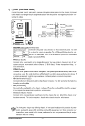
8) F_PANEL (Front Panel Header) Connect the power switch, reset switch, speaker and system status indicator on the chassis front panel to this header, make sure the wire assignments and the pin assignments are matched correctly. HD+ Power LED Chassis Intrusion Header Reset Switch Hard Drive Activity LED • MSG/PWR (Message/Power/Sleep LED): System Status LED Connects to the reset switch on the chassis front panel. Hardware Installation - 16 - Speaker Power Switch Message/Power/ Sleep LED G.QBOFM 20 19 SPEAK- The LED S0 On is reading or writing data. • RES (...
8) F_PANEL (Front Panel Header) Connect the power switch, reset switch, speaker and system status indicator on the chassis front panel to this header, make sure the wire assignments and the pin assignments are matched correctly. HD+ Power LED Chassis Intrusion Header Reset Switch Hard Drive Activity LED • MSG/PWR (Message/Power/Sleep LED): System Status LED Connects to the reset switch on the chassis front panel. Hardware Installation - 16 - Speaker Power Switch Message/Power/ Sleep LED G.QBOFM 20 19 SPEAK- The LED S0 On is reading or writing data. • RES (...

Manual
Page 17
For information about connecting the front panel audio module that has different wire assignments, please contact the chassis manufacturer. 10) CD_IN (CD In Connector) You may connect your optical drive to the header. 1 Pin No. Definition 1 CD-L 2 GND 3 GND 4 CD-R - 17 - ously. • Some chassis provide a front panel audio module that came with your chassis front panel audio module to work or even damage it. You may connect the audio cable that has separated connectors on both of the motherboard header. For HD Front Panel Audio: For AC'97 Front Panel Audio:...
For information about connecting the front panel audio module that has different wire assignments, please contact the chassis manufacturer. 10) CD_IN (CD In Connector) You may connect your optical drive to the header. 1 Pin No. Definition 1 CD-L 2 GND 3 GND 4 CD-R - 17 - ously. • Some chassis provide a front panel audio module that came with your chassis front panel audio module to work or even damage it. You may connect the audio cable that has separated connectors on both of the motherboard header. For HD Front Panel Audio: For AC'97 Front Panel Audio:...

Manual
Page 18
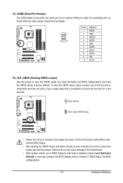
Definition 1 SPDIFO 2 GND 12) F_USB1/F_USB2 (USB Headers) The headers conform to certain expansion cards like graphics cards and sound cards. 11) SPDIF_O (S/PDIF Out Header) This header supports digital S/PDIF Out and connects a S/PDIF digital audio cable (provided by expansion cards) for digital audio output from your motherboard to your graphics card if you to use a S/PDIF digital audio cable for digital audio output from the power outlet to prevent damage to the USB bracket. Definition 1 Power (5V) 9 1 10 2 2 Power (5V) 3 USB DX4 USB DY- 5 USB DX+ 6 USB DY+ 7 GND...
Definition 1 SPDIFO 2 GND 12) F_USB1/F_USB2 (USB Headers) The headers conform to certain expansion cards like graphics cards and sound cards. 11) SPDIF_O (S/PDIF Out Header) This header supports digital S/PDIF Out and connects a S/PDIF digital audio cable (provided by expansion cards) for digital audio output from your motherboard to your graphics card if you to use a S/PDIF digital audio cable for digital audio output from the power outlet to prevent damage to the USB bracket. Definition 1 Power (5V) 9 1 10 2 2 Power (5V) 3 USB DX4 USB DY- 5 USB DX+ 6 USB DY+ 7 GND...
Manual
Page 19
Failure to do so may cause damage to the motherboard. • After system restart, go to BIOS Setup to load factory defaults (select Load Optimized Defaults) or manually configure the BIOS settings (refer to Chapter 2, "BIOS Setup," for a few seconds. Open: Normal Short: Clear CMOS Values • Always turn off your computer and unplug the power cord from the power outlet before clearing the CMOS values. • After clearing the CMOS values and before turning on the two pins to temporarily short the two pins or use a metal object like a screwdriver to factory defaults. To clear ...
Failure to do so may cause damage to the motherboard. • After system restart, go to BIOS Setup to load factory defaults (select Load Optimized Defaults) or manually configure the BIOS settings (refer to Chapter 2, "BIOS Setup," for a few seconds. Open: Normal Short: Clear CMOS Values • Always turn off your computer and unplug the power cord from the power outlet before clearing the CMOS values. • After clearing the CMOS values and before turning on the two pins to temporarily short the two pins or use a metal object like a screwdriver to factory defaults. To clear ...
Manual
Page 20
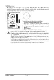
Turn off your computer and unplug the power cord before replacing the battery. • Replace the battery with an equivalent one minute. (Or use a metal object like a screwdriver to touch the positive and negative terminals of the battery (the positive side should face up). • Used batteries must be lost. Replace the battery when the battery voltage drops to a low level, or the CMOS values may not be accurate or may clear the CMOS values by yourself or uncertain about the battery model. • When installing the battery, note the orientation of the positive side (+) and the ...
Turn off your computer and unplug the power cord before replacing the battery. • Replace the battery with an equivalent one minute. (Or use a metal object like a screwdriver to touch the positive and negative terminals of the battery (the positive side should face up). • Used batteries must be lost. Replace the battery when the battery voltage drops to a low level, or the CMOS values may not be accurate or may clear the CMOS values by yourself or uncertain about the battery model. • When installing the battery, note the orientation of the positive side (+) and the ...
