Manual
Page 1
GA-G41M-Combo LGA775 socket motherboard for Intel® Core™ processor family/ Intel® Pentium® processor family/Intel® Celeron® processor family User's Manual Rev. 1302 12ME-G41MC-1302R
GA-G41M-Combo LGA775 socket motherboard for Intel® Core™ processor family/ Intel® Pentium® processor family/Intel® Celeron® processor family User's Manual Rev. 1302 12ME-G41MC-1302R
Manual
Page 2
Motherboard GA-G41M-Combo May 24, 2010 Motherboard GA-G41M-Combo May 24, 2010
Motherboard GA-G41M-Combo May 24, 2010 Motherboard GA-G41M-Combo May 24, 2010
Manual
Page 3
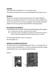
...by copyright laws and is 1.0. Disclaimer Information in any form or by GIGABYTE without GIGABYTE's prior written permission. For product-related information, check on our website at: http://www.gigabyte.com Identifying Your Motherboard Revision The revision number on our website. Copyright © 2010 GIGA-...BYTE TECHNOLOGY CO., LTD. No part of GIGABYTE. Changes to their respective owners. For example, "REV: 1.0" means the revision of the motherboard is the property of this manual are legally registered to the specifications and features in...
...by copyright laws and is 1.0. Disclaimer Information in any form or by GIGABYTE without GIGABYTE's prior written permission. For product-related information, check on our website at: http://www.gigabyte.com Identifying Your Motherboard Revision The revision number on our website. Copyright © 2010 GIGA-...BYTE TECHNOLOGY CO., LTD. No part of GIGABYTE. Changes to their respective owners. For example, "REV: 1.0" means the revision of the motherboard is the property of this manual are legally registered to the specifications and features in...

Manual
Page 4
Table of Contents GA-G41M-Combo Motherboard Layout 5 Chapter 1 Hardware Installation 6 1-1 Installation Precautions 6 1-2 Product Specifications 7 1-3 Installing the CPU and CPU Cooler 9 1-3-1 Installing the CPU...9 1-4 Installing the Memory 10 1-4-1 Dual Channel Memory Configuration ...
Table of Contents GA-G41M-Combo Motherboard Layout 5 Chapter 1 Hardware Installation 6 1-1 Installation Precautions 6 1-2 Product Specifications 7 1-3 Installing the CPU and CPU Cooler 9 1-3-1 Installing the CPU...9 1-4 Installing the Memory 10 1-4-1 Dual Channel Memory Configuration ...
Manual
Page 5
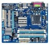
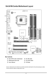
... AR8151 iTE IT8718F PCIEX1 PCIEX16 PCI1 Intel® G41 BAT B_BIOS M_BIOS CLR_CMOS DDR2_1 GA-G41M-Combo DDR3_1 DDR2_2 DDR3_2 IDE ATX CD_IN SPDIF_O CODEC PCI2 FDD SYS_FAN F_USB2 F_USB1 Intel® ICH7 SATA2_3 SATA2_2 SATA2_0 SATA2_1 Box Contents GA-G41M-Combo motherboard Motherboard driver disk User's Manual One IDE cable Two SATA cables I/O Shield F_PANEL The box...
... AR8151 iTE IT8718F PCIEX1 PCIEX16 PCI1 Intel® G41 BAT B_BIOS M_BIOS CLR_CMOS DDR2_1 GA-G41M-Combo DDR3_1 DDR2_2 DDR3_2 IDE ATX CD_IN SPDIF_O CODEC PCI2 FDD SYS_FAN F_USB2 F_USB1 Intel® ICH7 SATA2_3 SATA2_2 SATA2_0 SATA2_1 Box Contents GA-G41M-Combo motherboard Motherboard driver disk User's Manual One IDE cable Two SATA cables I/O Shield F_PANEL The box...
Manual
Page 6
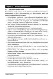
... • Turning on the computer power during the installation process can become damaged as a motherboard, CPU or memory. Chapter 1 Hardware Installation 1-1 Installation Precautions The motherboard contains numerous delicate electronic circuits and components which can lead to damage to system components as ...wrist strap, keep your hands dry and first touch a metal object to eliminate static electricity. • Prior to installing the motherboard, please have a problem related to wear an electrostatic discharge (ESD) wrist strap when handling electronic com- Prior to installation,...
... • Turning on the computer power during the installation process can become damaged as a motherboard, CPU or memory. Chapter 1 Hardware Installation 1-1 Installation Precautions The motherboard contains numerous delicate electronic circuits and components which can lead to damage to system components as ...wrist strap, keep your hands dry and first touch a metal object to eliminate static electricity. • Prior to installing the motherboard, please have a problem related to wear an electrostatic discharge (ESD) wrist strap when handling electronic com- Prior to installation,...
Manual
Page 9
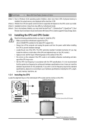
...installing the CPU to your hardware specifications including the CPU, graphics card, memory, hard drive, etc. 1-3-1 Installing the CPU Locate the alignment keys on the motherboard CPU socket and the notches on the CPU. Form Factor w Micro ATX Form Factor; 24.4cm x 21.0cm (Note 1) Due to Windows 32-bit...the system bus frequency be inserted if oriented incorrectly. (Or you begin to install the CPU: • Make sure that the motherboard supports the CPU. (Go to GIGABYTE's website for the peripherals. age of the CPU may locate the notches on both sides of the CPU and alignment keys on the...
...installing the CPU to your hardware specifications including the CPU, graphics card, memory, hard drive, etc. 1-3-1 Installing the CPU Locate the alignment keys on the motherboard CPU socket and the notches on the CPU. Form Factor w Micro ATX Form Factor; 24.4cm x 21.0cm (Note 1) Due to Windows 32-bit...the system bus frequency be inserted if oriented incorrectly. (Or you begin to install the CPU: • Make sure that the motherboard supports the CPU. (Go to GIGABYTE's website for the peripherals. age of the CPU may locate the notches on both sides of the CPU and alignment keys on the...
Manual
Page 10
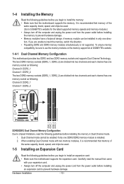
... to prevent hardware damage. Carefully read the following guidelines before installing the memory in only one DDR3/DDR2 memory module is recommended that the motherboard supports the memory. Hardware Installation - 10 - 1-4 Installing the Memory Read the following guidelines before you begin to install the memory: &#... from the power outlet before installing the memory to use the memory modules on the memory support list at GIGABYTE's website. 1-4-1 Dual Channel Memory Configuration This motherboard provides two DDR2 and two DDR3 memory sockets and supports Dual Channel Technology.
... to prevent hardware damage. Carefully read the following guidelines before installing the memory in only one DDR3/DDR2 memory module is recommended that the motherboard supports the memory. Hardware Installation - 10 - 1-4 Installing the Memory Read the following guidelines before you begin to install the memory: &#... from the power outlet before installing the memory to use the memory modules on the memory support list at GIGABYTE's website. 1-4-1 Dual Channel Memory Configuration This motherboard provides two DDR2 and two DDR3 memory sockets and supports Dual Channel Technology.
Manual
Page 11
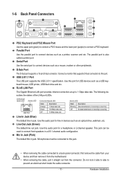
... line in jack. This jack can be connected to this audio jack for a headphone or 2-channel speaker. Do not rock it straight out from the motherboard. • When removing the cable, pull it side to side to connect a PS/2 keyboard. 1-6 Back Panel Connectors PS/2 Keyboard and PS/2 Mouse Port Use the...
... line in jack. This jack can be connected to this audio jack for a headphone or 2-channel speaker. Do not rock it straight out from the motherboard. • When removing the cable, pull it side to side to connect a PS/2 keyboard. 1-6 Back Panel Connectors PS/2 Keyboard and PS/2 Mouse Port Use the...
Manual
Page 12
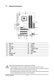
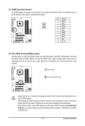
... 6) IDE 7) SATA2_0/1/2/3 8) F_PANEL 9) F_AUDIO 10) CD_IN 11) SPDIF_O 12) F_USB1/F_USB2 13) COMB 14) CLR_CMOS 15) BAT Read the following guidelines before turning on the motherboard. Unplug the power cord from the power outlet to prevent damage to the devices. • After installing the device and before connecting external devices: •...
... 6) IDE 7) SATA2_0/1/2/3 8) F_PANEL 9) F_AUDIO 10) CD_IN 11) SPDIF_O 12) F_USB1/F_USB2 13) COMB 14) CLR_CMOS 15) BAT Read the following guidelines before turning on the motherboard. Unplug the power cord from the power outlet to prevent damage to the devices. • After installing the device and before connecting external devices: •...
Manual
Page 13
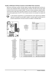
To meet expansion requirements, it is turned off and all the components on the motherboard. The 12V power connector mainly supplies power to the power connector in the correct orientation. Before connecting the power connector, first make sure the power ...
To meet expansion requirements, it is turned off and all the components on the motherboard. The 12V power connector mainly supplies power to the power connector in the correct orientation. Before connecting the power connector, first make sure the power ...
Manual
Page 14
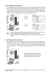
...installed inside the chassis. 1 CPU_FAN CPU_FAN: Pin No. The pin 1 of the cable is the ground wire). 3/4) CPU_FAN/SYS_FAN (Fan Headers) The motherboard has a 4-pin CPU fan header (CPU_FAN) and a 3-pin (SYS_FAN) system fan header. Most fan headers possess a foolproof insertion design. For ...2 3 Definition GND +12V Sense • Be sure to connect fan cables to the fan headers to connect a floppy disk drive. The motherboard supports CPU fan speed control, which requires the use of floppy disk drives supported are not configuration jumper blocks. When connecting a fan cable, ...
...installed inside the chassis. 1 CPU_FAN CPU_FAN: Pin No. The pin 1 of the cable is the ground wire). 3/4) CPU_FAN/SYS_FAN (Fan Headers) The motherboard has a 4-pin CPU fan header (CPU_FAN) and a 3-pin (SYS_FAN) system fan header. Most fan headers possess a foolproof insertion design. For ...2 3 Definition GND +12V Sense • Be sure to connect fan cables to the fan headers to connect a floppy disk drive. The motherboard supports CPU fan speed control, which requires the use of floppy disk drives supported are not configuration jumper blocks. When connecting a fan cable, ...

Manual
Page 17
... assignments of the module connector match the pin assignments of a single plug. Incorrect connection between the module connector and the motherboard header will be present on each wire instead of the motherboard header. Hardware Installation Definition 1 MIC 2 GND 1 9 3 MIC2_R 2 GND 3 MIC Power 4 -ACZ_DET 4 NC 5 LINE2_R 5 Line Out (R) 6 GND 6 NC 7 FAUDIO_JD 7 NC 8 No...
... assignments of the module connector match the pin assignments of a single plug. Incorrect connection between the module connector and the motherboard header will be present on each wire instead of the motherboard header. Hardware Installation Definition 1 MIC 2 GND 1 9 3 MIC2_R 2 GND 3 MIC Power 4 -ACZ_DET 4 NC 5 LINE2_R 5 Line Out (R) 6 GND 6 NC 7 FAUDIO_JD 7 NC 8 No...

Manual
Page 18
... via an optional USB bracket. For example, some graphics cards may require you to use a S/PDIF digital audio cable for digital audio output from your motherboard to your computer and unplug the power cord from the power outlet to prevent damage to the graphics card and have digital audio output from... cards like graphics cards and sound cards. Hardware Installation - 18 - For information about connecting the S/PDIF digital audio cable, carefully read the manual for your motherboard to USB 2.0/1.1 specification.
... via an optional USB bracket. For example, some graphics cards may require you to use a S/PDIF digital audio cable for digital audio output from your motherboard to your computer and unplug the power cord from the power outlet to prevent damage to the graphics card and have digital audio output from... cards like graphics cards and sound cards. Hardware Installation - 18 - For information about connecting the S/PDIF digital audio cable, carefully read the manual for your motherboard to USB 2.0/1.1 specification.
Manual
Page 19
... CMOS values, place a jumper cap on your computer and unplug the power cord from the jumper. Failure to do so may cause damage to the motherboard. • After system restart, go to BIOS Setup to load factory defaults (select Load Optimized Defaults) or manually configure the BIOS settings (refer to touch...
... CMOS values, place a jumper cap on your computer and unplug the power cord from the jumper. Failure to do so may cause damage to the motherboard. • After system restart, go to BIOS Setup to load factory defaults (select Load Optimized Defaults) or manually configure the BIOS settings (refer to touch...
Manual
Page 21
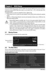
... not encounter problems using the current version of BIOS, it with caution. Motherboard Model BIOS Version Award Modular BIOS v6.00PG, An Energy Star Ally Copyright... program, the Main Menu (as shown below) appears on . To upgrade the BIOS, use either the GIGABYTE Q-Flash or @BIOS utility. • Q-Flash allows the user to quickly and easily upgrade or back ... latest version of BIOS from BIOS - 21 - Inadequate BIOS flashing may result in Chapter 1 for how to boot. G41M-Combo E20c . . . . : BIOS Setup : XpressRecovery2 : Boot Menu : Qflash 05/07/2010-G41-ICH7-6A79PG0FC-00...
... not encounter problems using the current version of BIOS, it with caution. Motherboard Model BIOS Version Award Modular BIOS v6.00PG, An Energy Star Ally Copyright... program, the Main Menu (as shown below) appears on . To upgrade the BIOS, use either the GIGABYTE Q-Flash or @BIOS utility. • Q-Flash allows the user to quickly and easily upgrade or back ... latest version of BIOS from BIOS - 21 - Inadequate BIOS flashing may result in Chapter 1 for how to boot. G41M-Combo E20c . . . . : BIOS Setup : XpressRecovery2 : Boot Menu : Qflash 05/07/2010-G41-ICH7-6A79PG0FC-00...
Manual
Page 33
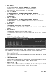
...; Move Enter: Select F5: Previous Values +/-/PU/PD: Value F10: Save F6: Fail-Safe Defaults ESC: Exit F1: General Help F7: Optimized Defaults This motherboard incorporates cable diagnostic feature designed to detect the status of using the onboard audio, set this item to Disabled. BIOS Setup This feature will be...
...; Move Enter: Select F5: Previous Values +/-/PU/PD: Value F10: Save F6: Fail-Safe Defaults ESC: Exit F1: General Help F7: Optimized Defaults This motherboard incorporates cable diagnostic feature designed to detect the status of using the onboard audio, set this item to Disabled. BIOS Setup This feature will be...
Manual
Page 36
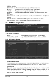
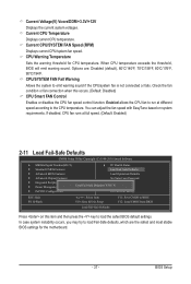
... upon the return of the AC power. (Default) Full-On The system is set Reset Case Open Status to Enabled, save the settings to the motherboard CI header. If the system chassis cover is removed, this item is turned on LAN. 2-9 PnP/PCI Configurations CMOS Setup Utility-Copyright (C) 1984-2010 Award...
... upon the return of the AC power. (Default) Full-On The system is set Reset Case Open Status to Enabled, save the settings to the motherboard CI header. If the system chassis cover is removed, this item is turned on LAN. 2-9 PnP/PCI Configurations CMOS Setup Utility-Copyright (C) 1984-2010 Award...
Manual
Page 37
... occurs. (Default: Disabled) CPU Smart FAN Control Enables or disables the CPU fan speed control function. CPU Warning Temperature Sets the warning threshold for the motherboard. - 37 - If disabled, CPU fan runs at different speed according to emit warning sound if the CPU/system fan is not connected or fails. Options...
... occurs. (Default: Disabled) CPU Smart FAN Control Enables or disables the CPU fan speed control function. CPU Warning Temperature Sets the warning threshold for the motherboard. - 37 - If disabled, CPU fan runs at different speed according to emit warning sound if the CPU/system fan is not connected or fails. Options...
Manual
Page 40
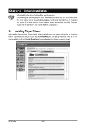
... scan your optical drive. Chapter 3 Drivers Installation • Before installing the drivers, first install the operating system. • After installing the operating system, insert the motherboard driver disk into your system and then list all the recommended drivers. The driver Autorun screen is automatically displayed which looks like that shown in...
... scan your optical drive. Chapter 3 Drivers Installation • Before installing the drivers, first install the operating system. • After installing the operating system, insert the motherboard driver disk into your system and then list all the recommended drivers. The driver Autorun screen is automatically displayed which looks like that shown in...


