Manual
Page 1
GA-G41M-Combo LGA775 socket motherboard for Intel® Core™ processor family/ Intel® Pentium® processor family/Intel® Celeron® processor family User's Manual Rev. 1302 12ME-G41MC-1302R
GA-G41M-Combo LGA775 socket motherboard for Intel® Core™ processor family/ Intel® Pentium® processor family/Intel® Celeron® processor family User's Manual Rev. 1302 12ME-G41MC-1302R
Manual
Page 2
Motherboard GA-G41M-Combo May 24, 2010 Motherboard GA-G41M-Combo May 24, 2010
Motherboard GA-G41M-Combo May 24, 2010 Motherboard GA-G41M-Combo May 24, 2010
Manual
Page 3
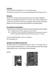
...copied, translated, transmitted, or published in the use of this product, GIGABYTE provides the following types of GIGABYTE. All rights reserved. For example, "REV: 1.0" means the revision of the motherboard is the property of documentations: For detailed product information, carefully ... and features in this manual may be made by GIGABYTE without GIGABYTE's prior written permission. For product-related information, check on our website at: http://www.gigabyte.com Identifying Your Motherboard Revision The revision number on our website. Example: Documentation...
...copied, translated, transmitted, or published in the use of this product, GIGABYTE provides the following types of GIGABYTE. All rights reserved. For example, "REV: 1.0" means the revision of the motherboard is the property of documentations: For detailed product information, carefully ... and features in this manual may be made by GIGABYTE without GIGABYTE's prior written permission. For product-related information, check on our website at: http://www.gigabyte.com Identifying Your Motherboard Revision The revision number on our website. Example: Documentation...

Manual
Page 4
Table of Contents GA-G41M-Combo Motherboard Layout 5 Chapter 1 Hardware Installation 6 1-1 Installation Precautions 6 1-2 Product Specifications 7 1-3 Installing the CPU and CPU Cooler 9 1-3-1 Installing the CPU...9 1-4 Installing the Memory 10 1-4-1 Dual Channel Memory Configuration ...
Table of Contents GA-G41M-Combo Motherboard Layout 5 Chapter 1 Hardware Installation 6 1-1 Installation Precautions 6 1-2 Product Specifications 7 1-3 Installing the CPU and CPU Cooler 9 1-3-1 Installing the CPU...9 1-4 Installing the Memory 10 1-4-1 Dual Channel Memory Configuration ...
Manual
Page 5
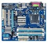
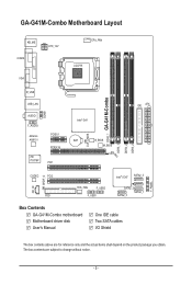
... AR8151 iTE IT8718F PCIEX1 PCIEX16 PCI1 Intel® G41 BAT B_BIOS M_BIOS CLR_CMOS DDR2_1 GA-G41M-Combo DDR3_1 DDR2_2 DDR3_2 IDE ATX CD_IN SPDIF_O CODEC PCI2 FDD SYS_FAN F_USB2 F_USB1 Intel® ICH7 SATA2_3 SATA2_2 SATA2_0 SATA2_1 Box Contents GA-G41M-Combo motherboard Motherboard driver disk User's Manual One IDE cable Two SATA cables I/O Shield F_PANEL The box...
... AR8151 iTE IT8718F PCIEX1 PCIEX16 PCI1 Intel® G41 BAT B_BIOS M_BIOS CLR_CMOS DDR2_1 GA-G41M-Combo DDR3_1 DDR2_2 DDR3_2 IDE ATX CD_IN SPDIF_O CODEC PCI2 FDD SYS_FAN F_USB2 F_USB1 Intel® ICH7 SATA2_3 SATA2_2 SATA2_0 SATA2_1 Box Contents GA-G41M-Combo motherboard Motherboard driver disk User's Manual One IDE cable Two SATA cables I/O Shield F_PANEL The box...
Manual
Page 6
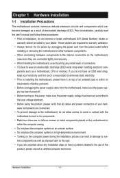
...not have an ESD wrist strap, keep your hands dry and first touch a metal object to eliminate static electricity. • Prior to installing the motherboard, please have a problem related to the local voltage standard. • Before using the product, please verify that all cables and power connectors of ... or have it on top of an antistatic pad or within an electrostatic shielding container. • Before unplugging the power supply cable from the motherboard, make sure the power supply has been turned off. • Before turning on the power, make sure the power supply voltage has been...
...not have an ESD wrist strap, keep your hands dry and first touch a metal object to eliminate static electricity. • Prior to installing the motherboard, please have a problem related to the local voltage standard. • Before using the product, please verify that all cables and power connectors of ... or have it on top of an antistatic pad or within an electrostatic shielding container. • Before unplugging the power supply cable from the motherboard, make sure the power supply has been turned off. • Before turning on the power, make sure the power supply voltage has been...
Manual
Page 9
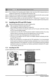
...your hardware specifications including the CPU, graphics card, memory, hard drive, etc. 1-3-1 Installing the CPU Locate the alignment keys on the motherboard CPU socket and the notches on the CPU Hardware Installation The CPU cannot be set the frequency beyond hardware specifications since it does not... the CPU fan speed control function is supported will depend on the computer if the CPU cooler is not recommended that the motherboard supports the CPU. (Go to GIGABYTE's website for the latest CPU support list.) • Always turn on the CPU cooler you install. (Note 3) Available ...
...your hardware specifications including the CPU, graphics card, memory, hard drive, etc. 1-3-1 Installing the CPU Locate the alignment keys on the motherboard CPU socket and the notches on the CPU Hardware Installation The CPU cannot be set the frequency beyond hardware specifications since it does not... the CPU fan speed control function is supported will depend on the computer if the CPU cooler is not recommended that the motherboard supports the CPU. (Go to GIGABYTE's website for the latest CPU support list.) • Always turn on the CPU cooler you install. (Note 3) Available ...
Manual
Page 10
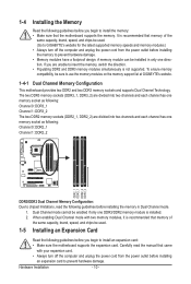
...the following guidelines before installing the memory in only one direction. It is recommended that the motherboard supports the memory. To ensure memory compatibility, be used . (Go to GIGABYTE's website for the latest supported memory speeds and memory modules.) • Always turn off the... memory sockets (DDR2_1, DDR2_2) are unable to use the memory modules on the memory support list at GIGABYTE's website. 1-4-1 Dual Channel Memory Configuration This motherboard provides two DDR2 and two DDR3 memory sockets and supports Dual Channel Technology. When enabling Dual Channel mode...
...the following guidelines before installing the memory in only one direction. It is recommended that the motherboard supports the memory. To ensure memory compatibility, be used . (Go to GIGABYTE's website for the latest supported memory speeds and memory modules.) • Always turn off the... memory sockets (DDR2_1, DDR2_2) are unable to use the memory modules on the memory support list at GIGABYTE's website. 1-4-1 Dual Channel Memory Configuration This motherboard provides two DDR2 and two DDR3 memory sockets and supports Dual Channel Technology. When enabling Dual Channel mode...
Manual
Page 11
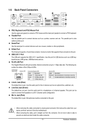
... connect a PS/2 mouse and the lower port (purple) to a back panel connector, first remove the cable from your device and then remove it from the motherboard. • When removing the cable, pull it side to side to connect front speakers in jack. Use this port. This jack can be connected to...
... connect a PS/2 mouse and the lower port (purple) to a back panel connector, first remove the cable from your device and then remove it from the motherboard. • When removing the cable, pull it side to side to connect front speakers in jack. Use this port. This jack can be connected to...
Manual
Page 12
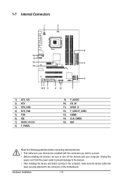
... 6) IDE 7) SATA2_0/1/2/3 8) F_PANEL 9) F_AUDIO 10) CD_IN 11) SPDIF_O 12) F_USB1/F_USB2 13) COMB 14) CLR_CMOS 15) BAT Read the following guidelines before turning on the motherboard. Unplug the power cord from the power outlet to prevent damage to the devices. • After installing the device and before connecting external devices: •...
... 6) IDE 7) SATA2_0/1/2/3 8) F_PANEL 9) F_AUDIO 10) CD_IN 11) SPDIF_O 12) F_USB1/F_USB2 13) COMB 14) CLR_CMOS 15) BAT Read the following guidelines before turning on the motherboard. Unplug the power cord from the power outlet to prevent damage to the devices. • After installing the device and before connecting external devices: •...
Manual
Page 13
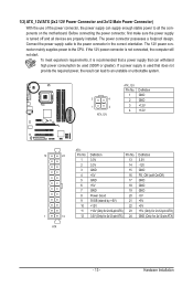
... power consumption be used (500W or greater). The power connector possesses a foolproof design. If a power supply is turned off and all the components on the motherboard.
... power consumption be used (500W or greater). The power connector possesses a foolproof design. If a power supply is turned off and all the components on the motherboard.
Manual
Page 14
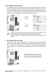
... drive cable. For purchasing the optional floppy disk drive cable, please contact the local dealer. 33 1 34 2 Hardware Installation - 14 - 3/4) CPU_FAN/SYS_FAN (Fan Headers) The motherboard has a 4-pin CPU fan header (CPU_FAN) and a 3-pin (SYS_FAN) system fan header. For optimum heat dissipation, it in damage to locate pin 1 of floppy disk...
... drive cable. For purchasing the optional floppy disk drive cable, please contact the local dealer. 33 1 34 2 Hardware Installation - 14 - 3/4) CPU_FAN/SYS_FAN (Fan Headers) The motherboard has a 4-pin CPU fan header (CPU_FAN) and a 3-pin (SYS_FAN) system fan header. For optimum heat dissipation, it in damage to locate pin 1 of floppy disk...

Manual
Page 17
... (HD) and AC'97 audio. Definition 2 10 1 MIC2_L Pin No. Hardware Installation Incorrect connection between the module connector and the motherboard header will be present on each wire instead of the motherboard header. Definition 1 MIC 2 GND 1 9 3 MIC2_R 2 GND 3 MIC Power 4 -ACZ_DET 4 NC 5 LINE2_R 5 Line Out (R) 6 GND 6 NC 7 FAUDIO_JD 7 NC 8 No Pin 8 No...
... (HD) and AC'97 audio. Definition 2 10 1 MIC2_L Pin No. Hardware Installation Incorrect connection between the module connector and the motherboard header will be present on each wire instead of the motherboard header. Definition 1 MIC 2 GND 1 9 3 MIC2_R 2 GND 3 MIC Power 4 -ACZ_DET 4 NC 5 LINE2_R 5 Line Out (R) 6 GND 6 NC 7 FAUDIO_JD 7 NC 8 No Pin 8 No...

Manual
Page 18
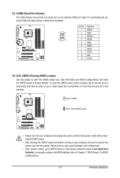
... plug the IEEE 1394 bracket (2x5-pin) cable into the USB header. • Prior to installing the USB bracket, be sure to turn off your motherboard to certain expansion cards like graphics cards and sound cards. Hardware Installation - 18 - Definition 1 SPDIFO 2 GND 12) F_USB1/F_USB2 (USB Headers) The headers conform to... audio cable for your graphics card if you wish to connect an HDMI display to the graphics card and have digital audio output from your motherboard to USB 2.0/1.1 specification.
... plug the IEEE 1394 bracket (2x5-pin) cable into the USB header. • Prior to installing the USB bracket, be sure to turn off your motherboard to certain expansion cards like graphics cards and sound cards. Hardware Installation - 18 - Definition 1 SPDIFO 2 GND 12) F_USB1/F_USB2 (USB Headers) The headers conform to... audio cable for your graphics card if you wish to connect an HDMI display to the graphics card and have digital audio output from your motherboard to USB 2.0/1.1 specification.
Manual
Page 19
... the two pins or use a metal object like a screwdriver to Chapter 2, "BIOS Setup," for a few seconds. Failure to do so may cause damage to the motherboard. • After system restart, go to BIOS Setup to load factory defaults (select Load Optimized Defaults) or manually configure the BIOS settings (refer to touch...
... the two pins or use a metal object like a screwdriver to Chapter 2, "BIOS Setup," for a few seconds. Failure to do so may cause damage to the motherboard. • After system restart, go to BIOS Setup to load factory defaults (select Load Optimized Defaults) or manually configure the BIOS settings (refer to touch...
Manual
Page 21
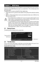
... the BIOS, use either the GIGABYTE Q-Flash or @BIOS utility. • Q-Flash allows the user to BIOS F12: Load CMOS from the Internet and updates the BIOS. • Because BIOS flashing is recommended that you not alter the default settings (unless you not flash the BIOS. G41M-Combo E20c . . . . : ... the BIOS Setup program, the Main Menu (as shown below) appears on . If this chapter or introductions of the BIOS Setup program. Motherboard Model BIOS Version Award Modular BIOS v6.00PG, An Energy Star Ally Copyright (C) 1984-2010, Award Software, Inc. BIOS Setup Inadequately altering ...
... the BIOS, use either the GIGABYTE Q-Flash or @BIOS utility. • Q-Flash allows the user to BIOS F12: Load CMOS from the Internet and updates the BIOS. • Because BIOS flashing is recommended that you not alter the default settings (unless you not flash the BIOS. G41M-Combo E20c . . . . : ... the BIOS Setup program, the Main Menu (as shown below) appears on . If this chapter or introductions of the BIOS Setup program. Motherboard Model BIOS Version Award Modular BIOS v6.00PG, An Energy Star Ally Copyright (C) 1984-2010, Award Software, Inc. BIOS Setup Inadequately altering ...
Manual
Page 33
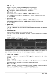
...; Move Enter: Select F5: Previous Values +/-/PU/PD: Value F10: Save F6: Fail-Safe Defaults ESC: Exit F1: General Help F7: Optimized Defaults This motherboard incorporates cable diagnostic feature designed to detect the status of using the onboard audio, set this item to Disabled. Onboard Serial Port 2 Enables or disables...
...; Move Enter: Select F5: Previous Values +/-/PU/PD: Value F10: Save F6: Fail-Safe Defaults ESC: Exit F1: General Help F7: Optimized Defaults This motherboard incorporates cable diagnostic feature designed to detect the status of using the onboard audio, set this item to Disabled. Onboard Serial Port 2 Enables or disables...
Manual
Page 36
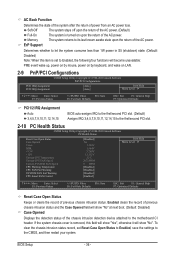
... the AC power. (Default) Full-On The system is removed, this item is set Reset Case Open Status to Enabled, save the settings to the motherboard CI header. Enabled clears the record of previous chassis intrusion status and the Case Opened field will show "No" at next boot. (Default: Disabled) Case...
... the AC power. (Default) Full-On The system is removed, this item is set Reset Case Open Status to Enabled, save the settings to the motherboard CI header. Enabled clears the record of previous chassis intrusion status and the Case Opened field will show "No" at next boot. (Default: Disabled) Case...
Manual
Page 37
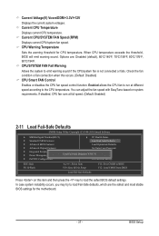
...-Safe Defaults F11: Save CMOS to BIOS F12: Load CMOS from BIOS Press on system requirements. CPU Warning Temperature Sets the warning threshold for the motherboard. - 37 - You can adjust the fan speed with EasyTune based on this occurs. (Default: Disabled) CPU Smart FAN Control Enables or disables the CPU fan...
...-Safe Defaults F11: Save CMOS to BIOS F12: Load CMOS from BIOS Press on system requirements. CPU Warning Temperature Sets the warning threshold for the motherboard. - 37 - You can adjust the fan speed with EasyTune based on this occurs. (Default: Disabled) CPU Smart FAN Control Enables or disables the CPU fan...
Manual
Page 40
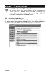
... you wish to install. Chapter 3 Drivers Installation • Before installing the drivers, first install the operating system. • After installing the operating system, insert the motherboard driver disk into your system and then list all the drivers that shown in the screen shot below. (If the driver Autorun screen does not...
... you wish to install. Chapter 3 Drivers Installation • Before installing the drivers, first install the operating system. • After installing the operating system, insert the motherboard driver disk into your system and then list all the drivers that shown in the screen shot below. (If the driver Autorun screen does not...


