Manual
Page 3
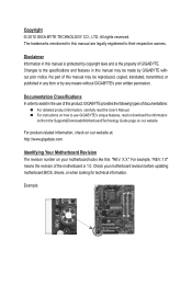
...Changes to the specifications and features in this product, GIGABYTE provides the following types of documentations: For detailed product information, carefully read the User's Manual. For instructions on how to use of this manual may be made by GIGABYTE without GIGABYTE's prior written ...motherboard BIOS, drivers, or when looking for technical information. For product-related information, check on our website at: http://www.gigabyte.com Identifying Your Motherboard Revision The revision number on our website. For example, "REV: 1.0" means the revision of the ...
...Changes to the specifications and features in this product, GIGABYTE provides the following types of documentations: For detailed product information, carefully read the User's Manual. For instructions on how to use of this manual may be made by GIGABYTE without GIGABYTE's prior written ...motherboard BIOS, drivers, or when looking for technical information. For product-related information, check on our website at: http://www.gigabyte.com Identifying Your Motherboard Revision The revision number on our website. For example, "REV: 1.0" means the revision of the ...

Manual
Page 4
Table of Contents GA-G41M-Combo Motherboard Layout 5 Chapter 1 Hardware Installation 6 1-1 Installation Precautions 6 1-2 Product Specifications 7 1-3 Installing the CPU and CPU Cooler 9 1-3-1 Installing the CPU...9 1-4 Installing the Memory 10 1-4-1 Dual Channel Memory Configuration 10 1-5 Installing an Expansion Card 10 1-6 Back Panel ...
Table of Contents GA-G41M-Combo Motherboard Layout 5 Chapter 1 Hardware Installation 6 1-1 Installation Precautions 6 1-2 Product Specifications 7 1-3 Installing the CPU and CPU Cooler 9 1-3-1 Installing the CPU...9 1-4 Installing the Memory 10 1-4-1 Dual Channel Memory Configuration 10 1-5 Installing an Expansion Card 10 1-6 Back Panel ...
Manual
Page 7
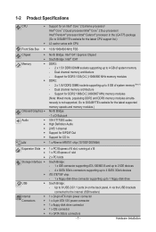
...: - 1 x floppy disk drive connector supporting up to 1 floppy disk drive USB South Bridge: - Go to GIGABYTE's website for the latest supported memory speeds and memory modules.) North Bridge: - 1 x D-Sub port VIA VT1708S codec High ...1 x 4-pin ATX 12V power connector w 1 x floppy disk drive connector w 1 x IDE connector w 4 x SATA 3Gb/s connectors - 7 - 1-2 Product Specifications CPU w w Support for an Intel® Core™ 2 Extreme processor/ Intel® Core™ 2 Quad processor/Intel® Core™ 2 Duo processor/...
...: - 1 x floppy disk drive connector supporting up to 1 floppy disk drive USB South Bridge: - Go to GIGABYTE's website for the latest supported memory speeds and memory modules.) North Bridge: - 1 x D-Sub port VIA VT1708S codec High ...1 x 4-pin ATX 12V power connector w 1 x floppy disk drive connector w 1 x IDE connector w 4 x SATA 3Gb/s connectors - 7 - 1-2 Product Specifications CPU w w Support for an Intel® Core™ 2 Extreme processor/ Intel® Core™ 2 Quad processor/Intel® Core™ 2 Duo processor/...
Manual
Page 9
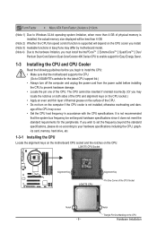
... sure that the motherboard supports the CPU. (Go to GIGABYTE's website for the peripherals. Notch Triangle Pin One Marking on the computer if the CPU cooler is supported will be set the frequency beyond hardware specifications since it does not meet the standard requirements for the latest...enable support for Easy Energy Saver. 1-3 Installing the CPU and CPU Cooler Read the following guidelines before installing the CPU to your hardware specifications including the CPU, graphics card, memory, hard drive, etc. 1-3-1 Installing the CPU Locate the alignment keys on the motherboard CPU ...
... sure that the motherboard supports the CPU. (Go to GIGABYTE's website for the peripherals. Notch Triangle Pin One Marking on the computer if the CPU cooler is supported will be set the frequency beyond hardware specifications since it does not meet the standard requirements for the latest...enable support for Easy Energy Saver. 1-3 Installing the CPU and CPU Cooler Read the following guidelines before installing the CPU to your hardware specifications including the CPU, graphics card, memory, hard drive, etc. 1-3-1 Installing the CPU Locate the alignment keys on the motherboard CPU ...
Manual
Page 11
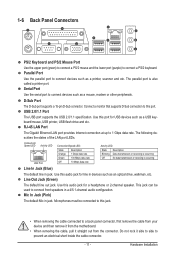
D-Sub Port The D-Sub port supports a 15-pin D-Sub connector. USB 2.0/1.1 Port The USB port supports the USB 2.0/1.1 specification. Use this audio jack for line in a 4/5.1-channel audio configuration. 1-6 Back Panel Connectors PS/2 Keyboard and PS/2 Mouse Port Use the upper port (green) to ...
D-Sub Port The D-Sub port supports a 15-pin D-Sub connector. USB 2.0/1.1 Port The USB port supports the USB 2.0/1.1 specification. Use this audio jack for line in a 4/5.1-channel audio configuration. 1-6 Back Panel Connectors PS/2 Keyboard and PS/2 Mouse Port Use the upper port (green) to ...

Manual
Page 18
... you wish to connect an HDMI display to the graphics card and have digital audio output from the power outlet to prevent damage to USB 2.0/1.1 specification. 11) SPDIF_O (S/PDIF Out Header) This header supports digital S/PDIF Out and connects a S/PDIF digital audio cable (provided by expansion cards) for digital audio output...
... you wish to connect an HDMI display to the graphics card and have digital audio output from the power outlet to prevent damage to USB 2.0/1.1 specification. 11) SPDIF_O (S/PDIF Out Header) This header supports digital S/PDIF Out and connects a S/PDIF digital audio cable (provided by expansion cards) for digital audio output...
Manual
Page 24
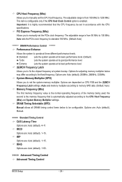
... Memory Multiplier settings. DRAM Timing Selectable (SPD) Manual allows all DRAM timing control items below may differ according to set in accordance with the CPU specifications. tRCD Options are : Auto (default), 4~11. Standard Lets the system operate at its basic performance level. (Default) Turbo Lets the system operate at three different...
... Memory Multiplier settings. DRAM Timing Selectable (SPD) Manual allows all DRAM timing control items below may differ according to set in accordance with the CPU specifications. tRCD Options are : Auto (default), 4~11. Standard Lets the system operate at its basic performance level. (Default) Turbo Lets the system operate at three different...
Manual
Page 28
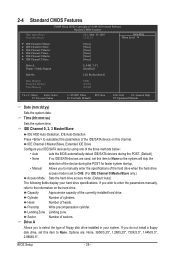
... : None, 360K/5.25", 1.2M/5.25", 720K/3.5", 1.44M/3.5", 2.88M/3.5". Options are used, set this item to manually enter the specifications of heads. IDE Channel 0 Master/Slave, Extended IDE Drive Configure your hard drive specifications. Sector Number of the currently installed hard drive. BIOS Setup - 28 - If you wish to enter the parameters manually...
... : None, 360K/5.25", 1.2M/5.25", 720K/3.5", 1.44M/3.5", 2.88M/3.5". Options are used, set this item to manually enter the specifications of heads. IDE Channel 0 Master/Slave, Extended IDE Drive Configure your hard drive specifications. Sector Number of the currently installed hard drive. BIOS Setup - 28 - If you wish to enter the parameters manually...
Manual
Page 35
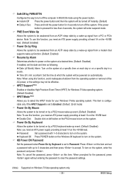
... to be turned on by a wake-up signal from the operating system or removal of Month) Alarm: Turn on the system at a specific time on each day or on a specific day in MS-DOS mode using this item and set to Enabled. (Default: 32-bit mode) Power On By Mouse Allows the...
... to be turned on by a wake-up signal from the operating system or removal of Month) Alarm: Turn on the system at a specific time on each day or on a specific day in MS-DOS mode using this item and set to Enabled. (Default: 32-bit mode) Power On By Mouse Allows the...