
Manual
Page 4
Installing the Infineon TPM Driver Insert the GIGABYTE motherboard driver disk. Click the Install All button and "Xpress Install" will automatically scan your system and list all of Smart TPM to install the Infineon ... Infineon TPM driver and the Smart TPM utility have been installed. 2.1. Click the Install button on the "Xpress Install" main menu to install it. Some motherboard driver disks include the Smart TPM utility in "Xpress Install." Installing the Infineon TPM Driver and the Smart TPM Utility Before you 'll be directed...
Installing the Infineon TPM Driver Insert the GIGABYTE motherboard driver disk. Click the Install All button and "Xpress Install" will automatically scan your system and list all of Smart TPM to install the Infineon ... Infineon TPM driver and the Smart TPM utility have been installed. 2.1. Click the Install button on the "Xpress Install" main menu to install it. Some motherboard driver disks include the Smart TPM utility in "Xpress Install." Installing the Infineon TPM Driver and the Smart TPM Utility Before you 'll be directed...

Manual
Page 7
... digits recommended) in Passkey which will store the encrypted TPM User Password in the system BIOS. Before creating a Bluetooth cell phone key, make sure your motherboard includes a Bluetooth receiver and turn on the search and Bluetooth functions on your cell phone. Selecting the Enable Backup to use as the portable Smart...
... digits recommended) in Passkey which will store the encrypted TPM User Password in the system BIOS. Before creating a Bluetooth cell phone key, make sure your motherboard includes a Bluetooth receiver and turn on the search and Bluetooth functions on your cell phone. Selecting the Enable Backup to use as the portable Smart...

Manual
Page 19
...'t display your Bluetooth-enabled cell phone, click Refresh to let Smart TPM re-detect the device.) Before creating a Bluetooth cell phone key, make sure your motherboard includes a Bluetooth receiver and turn off or reset your computer when a USB key is cancelled. 4.2. Then the USB key is being created. • If you...
...'t display your Bluetooth-enabled cell phone, click Refresh to let Smart TPM re-detect the device.) Before creating a Bluetooth cell phone key, make sure your motherboard includes a Bluetooth receiver and turn off or reset your computer when a USB key is cancelled. 4.2. Then the USB key is being created. • If you...
Manual
Page 3
... Install buttons on the right of the selected drivers, including the Infineon TPM driver and the GIGABYTE Ultra TPM utility. "Xpress Install" will automatically scan your system. Install the GIGABYTE Ultra TPM utility. - 3 - 2. Method 1: Insert the GIGABYTE motherboard driver disk. Click the Install All button. "Xpress Install" will install all the drivers that are...
... Install buttons on the right of the selected drivers, including the Infineon TPM driver and the GIGABYTE Ultra TPM utility. "Xpress Install" will automatically scan your system. Install the GIGABYTE Ultra TPM utility. - 3 - 2. Method 1: Insert the GIGABYTE motherboard driver disk. Click the Install All button. "Xpress Install" will install all the drivers that are...
Manual
Page 1
GA-EP45-DQ6 LGA775 socket motherboard for Intel® CoreTM processor family/ Intel® Pentium® processor family/Intel® Celeron® processor family User's Manual Rev. 1004 12ME-EP45DQ6-1004R
GA-EP45-DQ6 LGA775 socket motherboard for Intel® CoreTM processor family/ Intel® Pentium® processor family/Intel® Celeron® processor family User's Manual Rev. 1004 12ME-EP45DQ6-1004R

Manual
Page 2
Motherboard GA-EP45-DQ6 May 15, 2008 Motherboard GA-EP45-DQ6 May 15, 2008
Motherboard GA-EP45-DQ6 May 15, 2008 Motherboard GA-EP45-DQ6 May 15, 2008
Manual
Page 3
...., LTD. For product-related information, check on our website at: http://www.gigabyte.com.tw Identifying Your Motherboard Revision The revision number on our website. All rights reserved. GIGABYTE UNITED INC. No part of this manual are legally registered to assist in this... „ For quick set-up of the motherboard is exclusively licensed to use GIGABYTE's unique features, read or download the information on/from the Support\Motherboard\Technology Guide page on your motherboard revision before updating motherboard BIOS, drivers, or when looking for technical ...
...., LTD. For product-related information, check on our website at: http://www.gigabyte.com.tw Identifying Your Motherboard Revision The revision number on our website. All rights reserved. GIGABYTE UNITED INC. No part of this manual are legally registered to assist in this... „ For quick set-up of the motherboard is exclusively licensed to use GIGABYTE's unique features, read or download the information on/from the Support\Motherboard\Technology Guide page on your motherboard revision before updating motherboard BIOS, drivers, or when looking for technical ...
Manual
Page 4
Table of Contents Box Contents ...6 OptionalItems ...6 GA-EP45-DQ6 Motherboard Layout 7 Block Diagram ...8 Chapter 1 Hardware Installation 9 1-1 Installation Precautions 9 1-2 Product Specifications 10 1-3 Installing the CPU and CPU Cooler 13 1-3-1 Installing the CPU 13 1-3-2 Installing the CPU ...
Table of Contents Box Contents ...6 OptionalItems ...6 GA-EP45-DQ6 Motherboard Layout 7 Block Diagram ...8 Chapter 1 Hardware Installation 9 1-1 Installation Precautions 9 1-2 Product Specifications 10 1-3 Installing the CPU and CPU Cooler 13 1-3-1 Installing the CPU 13 1-3-2 Installing the CPU ...
Manual
Page 6
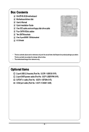
... power cable (Part No. 12CF1-2SERPW-01R) S/PDIF in cable (Part No. 12CR1-1SPDIN-01R) COM port cable (Part No. 12CF1-1CM001-32R) - 6 - Box Contents GA-EP45-DQ6 motherboard Motherboard driver disk User's Manual Quick Installation Guide One IDE cable and one floppy disk drive cable Four SATA 3Gb/s cables Two SATA brackets One 2-port... IEEE 1394a bracket I/O Shield • The box contents above are subject to change without notice. • The motherboard image is for reference only and the actual items shall depend on product package you obtain.
... power cable (Part No. 12CF1-2SERPW-01R) S/PDIF in cable (Part No. 12CR1-1SPDIN-01R) COM port cable (Part No. 12CF1-1CM001-32R) - 6 - Box Contents GA-EP45-DQ6 motherboard Motherboard driver disk User's Manual Quick Installation Guide One IDE cable and one floppy disk drive cable Four SATA 3Gb/s cables Two SATA brackets One 2-port... IEEE 1394a bracket I/O Shield • The box contents above are subject to change without notice. • The motherboard image is for reference only and the actual items shall depend on product package you obtain.
Manual
Page 7
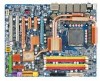
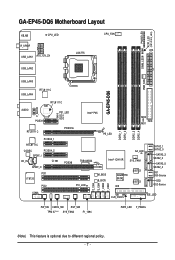
GA-EP45-DQ6 Motherboard Layout PHASE LED ACPI_LED (S0/1/3/4/5_LED) KB_MS CPU_LED CPU_FAN R_SPDIF ATX LGA775 USB_LAN1 ATX_12V_2X DIMM_LED USB_LAN2 PWR_FAN USB_LAN3 GA-EP45-DQ6 USB_LAN4 RTL8111C AUDIO RTL8111C BAT F_AUDIO PCIEX1 PE1_LED ...GD1 GD2 RTL8111C PCIEX16 PCIEX4_1 Intel® P45 PE_LED DDR2_1 DDR2_2 DDR2_3 DDR2_4 MD2 MD1 FDD RTL8111C CODEC PCIEX4_2 SPDIF_I CD_IN CI SPDIF_O PCI1 IT8720 PCI2 SA_LED PCIEX8 TSB43AB23 Intel® ICH10R SYS_FAN1 PCI_LED M_BIOS B_BIOS GIGABYTE...
GA-EP45-DQ6 Motherboard Layout PHASE LED ACPI_LED (S0/1/3/4/5_LED) KB_MS CPU_LED CPU_FAN R_SPDIF ATX LGA775 USB_LAN1 ATX_12V_2X DIMM_LED USB_LAN2 PWR_FAN USB_LAN3 GA-EP45-DQ6 USB_LAN4 RTL8111C AUDIO RTL8111C BAT F_AUDIO PCIEX1 PE1_LED ...GD1 GD2 RTL8111C PCIEX16 PCIEX4_1 Intel® P45 PE_LED DDR2_1 DDR2_2 DDR2_3 DDR2_4 MD2 MD1 FDD RTL8111C CODEC PCIEX4_2 SPDIF_I CD_IN CI SPDIF_O PCI1 IT8720 PCI2 SA_LED PCIEX8 TSB43AB23 Intel® ICH10R SYS_FAN1 PCI_LED M_BIOS B_BIOS GIGABYTE...
Manual
Page 9
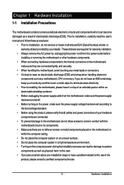
...for warranty validation. • Always remove the AC power by your hardware components are connected. • To prevent damage to the motherboard, do not have an ESD wrist strap, keep your hands dry and first touch a metal object to eliminate static electricity. •...the product, please verify that all cables and power connectors of your dealer. Hardware Installation Chapter 1 Hardware Installation 1-1 Installation Precautions The motherboard contains numerous delicate electronic circuits and components which can lead to damage to system components as well as physical harm to the user....
...for warranty validation. • Always remove the AC power by your hardware components are connected. • To prevent damage to the motherboard, do not have an ESD wrist strap, keep your hands dry and first touch a metal object to eliminate static electricity. •...the product, please verify that all cables and power connectors of your dealer. Hardware Installation Chapter 1 Hardware Installation 1-1 Installation Precautions The motherboard contains numerous delicate electronic circuits and components which can lead to damage to system components as well as physical harm to the user....
Manual
Page 10
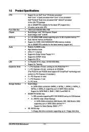
...of system memory (Note 1) Š Dual channel memory architecture Š Support for DDR2 1200/1066/800/667 MHz memory modules (Go to GIGABYTE's website for the latest memory support list.) Š Realtek ALC889A codec Š High Definition Audio Š 2/4/5.1/7.1-channel Š Support for... 0, RAID 1, RAID 5 and RAID 10 Š GIGABYTE SATA2 chip: - 1 x IDE connector supporting ATA-133/100/66/33 and up to 2 IDE devices Š 2 x SiI5723 chips (Smart Backup): - 4 x SATA 3Gb/s connectors (GS0-Source, GS1, GS2-Source, GS3) supporting up to 1 floppy disk drive GA-EP45-DQ6 Motherboard - 10 -
...of system memory (Note 1) Š Dual channel memory architecture Š Support for DDR2 1200/1066/800/667 MHz memory modules (Go to GIGABYTE's website for the latest memory support list.) Š Realtek ALC889A codec Š High Definition Audio Š 2/4/5.1/7.1-channel Š Support for... 0, RAID 1, RAID 5 and RAID 10 Š GIGABYTE SATA2 chip: - 1 x IDE connector supporting ATA-133/100/66/33 and up to 2 IDE devices Š 2 x SiI5723 chips (Smart Backup): - 4 x SATA 3Gb/s connectors (GS0-Source, GS1, GS2-Source, GS3) supporting up to 1 floppy disk drive GA-EP45-DQ6 Motherboard - 10 -
Manual
Page 12
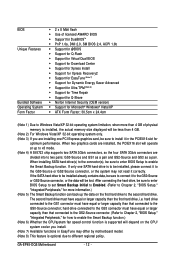
... Backup function.) (Note 6) Whether the CPU/system fan speed control function is supported will depend on the first hard drive to the second hard drive. GA-EP45-DQ6 Motherboard - 12 - When two graphics cards are installed, the PCIEX16 slot will operate at up the data on the CPU/ system cooler you are divided into..., the actual memory size displayed will be installed, please connect it to the GS0-Source or GS2-Source connector, or the system may differ by motherboard model. (Note 8) This feature is optional due to different regional policy.
... Backup function.) (Note 6) Whether the CPU/system fan speed control function is supported will depend on the first hard drive to the second hard drive. GA-EP45-DQ6 Motherboard - 12 - When two graphics cards are installed, the PCIEX16 slot will operate at up the data on the CPU/ system cooler you are divided into..., the actual memory size displayed will be installed, please connect it to the GS0-Source or GS2-Source connector, or the system may differ by motherboard model. (Note 8) This feature is optional due to different regional policy.
Manual
Page 13
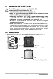
mended that the motherboard supports the CPU. (Go to GIGABYTE's website for the peripherals. 1-3 Installing the CPU and CPU Cooler Read the following guidelines before installing the CPU to prevent hardware damage. • Locate the ... for the latest CPU support list.) • Always turn on the computer if the CPU cooler is not recom- Locate the alignment keys on the motherboard CPU socket and the notches on the CPU - 13 - LGA775 CPU Socket Alignment Key LGA 775 CPU Alignment Key Pin One Corner of the CPU...
mended that the motherboard supports the CPU. (Go to GIGABYTE's website for the peripherals. 1-3 Installing the CPU and CPU Cooler Read the following guidelines before installing the CPU to prevent hardware damage. • Locate the ... for the latest CPU support list.) • Always turn on the computer if the CPU cooler is not recom- Locate the alignment keys on the motherboard CPU socket and the notches on the CPU - 13 - LGA775 CPU Socket Alignment Key LGA 775 CPU Alignment Key Pin One Corner of the CPU...
Manual
Page 14
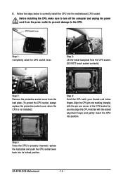
... one marking (triangle) with the pin one corner of the CPU socket (or you may align the CPU notches with your thumb and index fingers. GA-EP45-DQ6 Motherboard - 14 - Follow the steps below to the CPU. B. Before installing the CPU, make sure to turn off the computer and unplug the power cord from... into position. Step 5: Once the CPU is not installed.) Step 4: Hold the CPU with the socket alignment keys) and gently insert the CPU into the motherboard CPU socket.
... one marking (triangle) with the pin one corner of the CPU socket (or you may align the CPU notches with your thumb and index fingers. GA-EP45-DQ6 Motherboard - 14 - Follow the steps below to the CPU. B. Before installing the CPU, make sure to turn off the computer and unplug the power cord from... into position. Step 5: Once the CPU is not installed.) Step 4: Hold the CPU with the socket alignment keys) and gently insert the CPU into the motherboard CPU socket.
Manual
Page 15
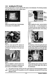
... is complete. Check that the Male and Female push pins are joined closely. (Refer to your CPU cooler installation manual for instructions on the motherboard. Step 6: Finally, attach the power connector of the CPU cooler to the CPU fan header (CPU_FAN) on installing the cooler.) Step 5: After..., check the back of the installed CPU. 1-3-2 Installing the CPU Cooler Follow the steps below to correctly install the CPU cooler on the motherboard. (The following procedure uses Intel® boxed cooler as the picture above, the installation is to install.) Step 3: Place the cooler atop...
... is complete. Check that the Male and Female push pins are joined closely. (Refer to your CPU cooler installation manual for instructions on the motherboard. Step 6: Finally, attach the power connector of the CPU cooler to the CPU fan header (CPU_FAN) on installing the cooler.) Step 5: After..., check the back of the installed CPU. 1-3-2 Installing the CPU Cooler Follow the steps below to correctly install the CPU cooler on the motherboard. (The following procedure uses Intel® boxed cooler as the picture above, the installation is to install.) Step 3: Place the cooler atop...
Manual
Page 16
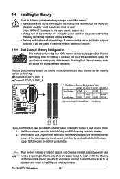
1-4 Installing the Memory Read the following guidelines before installing the memory to GIGABYTE's website for optimum performance. After the memory is installed, the BIOS will automatically detect the specifications and capacity of different capacity... Channel Memory Configurations Table DDR2_1 DDR2_2 DDR2_3 DDR2_4 Two Modules DS/SS - - Dual Channel mode cannot be installed in Dual Channel mode/performance. GA-EP45-DQ6 Motherboard - 16 - It is recommended that memory of the same capacity, brand, speed, and chips be populated and remain in only one DDR2 memory...
1-4 Installing the Memory Read the following guidelines before installing the memory to GIGABYTE's website for optimum performance. After the memory is installed, the BIOS will automatically detect the specifications and capacity of different capacity... Channel Memory Configurations Table DDR2_1 DDR2_2 DDR2_3 DDR2_4 Two Modules DS/SS - - Dual Channel mode cannot be installed in Dual Channel mode/performance. GA-EP45-DQ6 Motherboard - 16 - It is recommended that memory of the same capacity, brand, speed, and chips be populated and remain in only one DDR2 memory...
Manual
Page 17
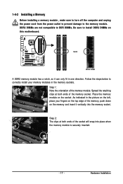
... , make sure to turn off the computer and unplug the power cord from the power outlet to prevent damage to install DDR2 DIMMs on this motherboard. DDR2 DIMMs are not compatible to DDR DIMMs. Be sure to the memory module. Step 2: The clips at both ends of the memory, push down...
... , make sure to turn off the computer and unplug the power cord from the power outlet to prevent damage to install DDR2 DIMMs on this motherboard. DDR2 DIMMs are not compatible to DDR DIMMs. Be sure to the memory module. Step 2: The clips at both ends of the memory, push down...
Manual
Page 18
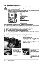
Install the driver provided with your computer. Make sure the card is securely seated in your card. GA-EP45-DQ6 Motherboard - 18 - • Removing the Card from the PCIEX16 slot: Gently push back on the lever on your expansion card. • Always turn off the computer ... expansion card(s). 7. Make sure the metal contacts on the top edge of the PCI Express slot to install an expansion card: • Make sure the motherboard supports the expansion card. Remove the metal slot cover from the power outlet before you begin to release the card and then pull the card...
Install the driver provided with your computer. Make sure the card is securely seated in your card. GA-EP45-DQ6 Motherboard - 18 - • Removing the Card from the PCIEX16 slot: Gently push back on the lever on your expansion card. • Always turn off the computer ... expansion card(s). 7. Make sure the metal contacts on the top edge of the PCI Express slot to install an expansion card: • Make sure the motherboard supports the expansion card. Remove the metal slot cover from the power outlet before you begin to release the card and then pull the card...
Manual
Page 19
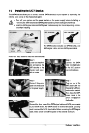
.... Step 3: Step 4: Connect the power Plug one free PCI slot and secure the SATA bracket to the chassis back panel with a screw. nector on your motherboard. 1-6 Installing the SATA Bracket The SATA bracket allows you only need to connect the SATA signal cable. For SATA device in external enclosure, you to...
.... Step 3: Step 4: Connect the power Plug one free PCI slot and secure the SATA bracket to the chassis back panel with a screw. nector on your motherboard. 1-6 Installing the SATA Bracket The SATA bracket allows you only need to connect the SATA signal cable. For SATA device in external enclosure, you to...


