Manual
Page 4
... ...6 GA-EP45-DQ6 Motherboard Layout 7 Block Diagram ...8 Chapter 1 Hardware Installation 9 1-1 Installation Precautions 9 1-2 Product Specifications 10 1-3 Installing the CPU and CPU Cooler 13 1-3-1 Installing the CPU 13 1-3-2 Installing the CPU Cooler 15 1-4 Installing the Memory 16 1-4-1 Dual Channel Memory Configuration 16 1-4-2 Installing a Memory 17 1-5 Installing an Expansion Card 18 1-6 Installing the SATA Bracket 19 1-7 Back Panel Connectors 20 1-8 Onboard LEDs and Switches 22 1-9 Internal Connectors 23 Chapter 2 BIOS Setup 35 2-1 Startup Screen 36 2-2 The Main Menu...
... ...6 GA-EP45-DQ6 Motherboard Layout 7 Block Diagram ...8 Chapter 1 Hardware Installation 9 1-1 Installation Precautions 9 1-2 Product Specifications 10 1-3 Installing the CPU and CPU Cooler 13 1-3-1 Installing the CPU 13 1-3-2 Installing the CPU Cooler 15 1-4 Installing the Memory 16 1-4-1 Dual Channel Memory Configuration 16 1-4-2 Installing a Memory 17 1-5 Installing an Expansion Card 18 1-6 Installing the SATA Bracket 19 1-7 Back Panel Connectors 20 1-8 Onboard LEDs and Switches 22 1-9 Internal Connectors 23 Chapter 2 BIOS Setup 35 2-1 Startup Screen 36 2-2 The Main Menu...
Manual
Page 10
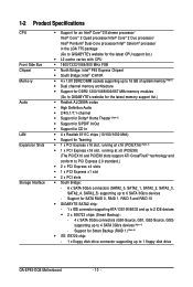
... 5) Š iTE IT8720 chip: - 1 x floppy disk drive connector supporting up to 4 SATA 3Gb/s devices (Note 4) - Support for SATA RAID 0, RAID 1, RAID 5 and RAID 10 Š GIGABYTE SATA2 chip: - 1 x IDE connector supporting ATA-133/100/66/33 and up to 2 IDE devices Š 2 x SiI5723 chips (Smart Backup): - 4 x SATA 3Gb/s connectors (GS0-Source, GS1, GS2-Source, GS3) supporting up to 6 SATA 3Gb/s devices - 1-2 Product Specifications CPU Front Side Bus Chipset Memory Audio LAN Expansion Slots Storage Interface Š Support for an Intel® CoreTM 2 Extreme processor/ Intel® CoreTM...
... 5) Š iTE IT8720 chip: - 1 x floppy disk drive connector supporting up to 4 SATA 3Gb/s devices (Note 4) - Support for SATA RAID 0, RAID 1, RAID 5 and RAID 10 Š GIGABYTE SATA2 chip: - 1 x IDE connector supporting ATA-133/100/66/33 and up to 2 IDE devices Š 2 x SiI5723 chips (Smart Backup): - 4 x SATA 3Gb/s connectors (GS0-Source, GS1, GS2-Source, GS3) supporting up to 6 SATA 3Gb/s devices - 1-2 Product Specifications CPU Front Side Bus Chipset Memory Audio LAN Expansion Slots Storage Interface Š Support for an Intel® CoreTM 2 Extreme processor/ Intel® CoreTM...
Manual
Page 12
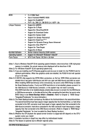
... (OEM version) Š Support for how to enable the Smart Backup function.) (Note 6) Whether the CPU/system fan speed control function is supported will depend on the first hard drive to two pairs: GS0-Source and GS1 as a pair and GS2-Source and GS3 as a pair. GA-EP45-DQ6 Motherboard - 12 - If the SATA hard drive to be installed already contains data, be sure to the GS0-Source connector; hard drive connected to...
... (OEM version) Š Support for how to enable the Smart Backup function.) (Note 6) Whether the CPU/system fan speed control function is supported will depend on the first hard drive to two pairs: GS0-Source and GS1 as a pair and GS2-Source and GS3 as a pair. GA-EP45-DQ6 Motherboard - 12 - If the SATA hard drive to be installed already contains data, be sure to the GS0-Source connector; hard drive connected to...
Manual
Page 16
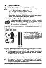
... Memory Mode will appear during the POST. The four DDR2 memory sockets are installed, a message which says memory is recommended that memory of the same capacity, brand, speed, and chips be enabled if only one direction. Intel® Flex Memory Technology offers greater flexibility to upgrade by allowing different memory sizes to be used . (Go to GIGABYTE's website for optimum performance. After the memory is recommended that the motherboard supports the memory. 1-4 Installing...
... Memory Mode will appear during the POST. The four DDR2 memory sockets are installed, a message which says memory is recommended that memory of the same capacity, brand, speed, and chips be enabled if only one direction. Intel® Flex Memory Technology offers greater flexibility to upgrade by allowing different memory sizes to be used . (Go to GIGABYTE's website for optimum performance. After the memory is recommended that the motherboard supports the memory. 1-4 Installing...
Manual
Page 18
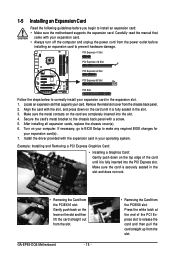
... expansion card in the expansion slot. 1. After installing all expansion cards, replace the chassis cover(s). 6. PCI Express x1 Slot PCI Express x16 Slot PCI Express x4 Slot PCI Express x8 Slot PCI Slot Follow the steps below to make any required BIOS changes for your expansion card(s). 7. Remove the metal slot cover from the slot. If necessary, go to BIOS Setup to correctly install your expansion card in your card. Carefully read the manual that supports your operating system. GA-EP45-DQ6 Motherboard - 18 - • Removing the Card from...
... expansion card in the expansion slot. 1. After installing all expansion cards, replace the chassis cover(s). 6. PCI Express x1 Slot PCI Express x16 Slot PCI Express x4 Slot PCI Express x8 Slot PCI Slot Follow the steps below to make any required BIOS changes for your expansion card(s). 7. Remove the metal slot cover from the slot. If necessary, go to BIOS Setup to correctly install your expansion card in your card. Carefully read the manual that supports your operating system. GA-EP45-DQ6 Motherboard - 18 - • Removing the Card from...
Manual
Page 32
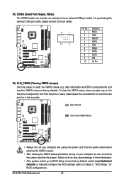
... to BIOS Setup to load factory defaults (select Load Optimized Defaults) or manually configure the BIOS settings (refer to clear the CMOS values (e.g. GA-EP45-DQ6 Motherboard - 32 - date information and BIOS configurations) and reset the CMOS values to remove the jumper cap from the power outlet before clearing the CMOS values. • After clearing the CMOS values and before turning on the two pins to temporarily short the two pins or use a metal object like a screwdriver to touch the two pins for BIOS configurations).
... to BIOS Setup to load factory defaults (select Load Optimized Defaults) or manually configure the BIOS settings (refer to clear the CMOS values (e.g. GA-EP45-DQ6 Motherboard - 32 - date information and BIOS configurations) and reset the CMOS values to remove the jumper cap from the power outlet before clearing the CMOS values. • After clearing the CMOS values and before turning on the two pins to temporarily short the two pins or use a metal object like a screwdriver to touch the two pins for BIOS configurations).
Manual
Page 36
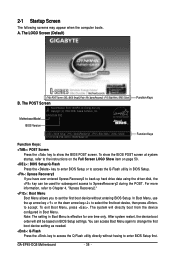
... access the Q-Flash utility directly without entering BIOS Setup. In Boot Menu, use the up hard drive data using the driver disk, the key can access Boot Menu again to change the first boot device setting as needed. : Q-Flash Press the key to XpressRecovery2 during the POST. Note: The setting in BIOS Setup. : Xpress Recovery2 If you to set the first boot device without having to enter BIOS Setup first. GA-EP45-DQ6 Motherboard - 36 - 2-1 Startup Screen The following screens may appear when the computer boots. Motherboard Model BIOS Version EP45-DQ6 F8C . . . . : BIOS Setup...
... access the Q-Flash utility directly without entering BIOS Setup. In Boot Menu, use the up hard drive data using the driver disk, the key can access Boot Menu again to change the first boot device setting as needed. : Q-Flash Press the key to XpressRecovery2 during the POST. Note: The setting in BIOS Setup. : Xpress Recovery2 If you to set the first boot device without having to enter BIOS Setup first. GA-EP45-DQ6 Motherboard - 36 - 2-1 Startup Screen The following screens may appear when the computer boots. Motherboard Model BIOS Version EP45-DQ6 F8C . . . . : BIOS Setup...
Manual
Page 38
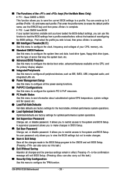
... CPU, memory, etc. „ Standard CMOS Features Use this menu to configure the system time and date, hard drive types, floppy disk drive types, and the type of errors that stop the system boot, etc. „ Advanced BIOS Features Use this menu to configure the device boot order, advanced features available on the CPU, and the primary display adapter. „ Integrated Peripherals Use this menu to configure all peripheral devices, such as IDE, SATA, USB, integrated audio, and integrated LAN, etc. „ Power Management Setup Use...
... CPU, memory, etc. „ Standard CMOS Features Use this menu to configure the system time and date, hard drive types, floppy disk drive types, and the type of errors that stop the system boot, etc. „ Advanced BIOS Features Use this menu to configure the device boot order, advanced features available on the CPU, and the primary display adapter. „ Integrated Peripherals Use this menu to configure all peripheral devices, such as IDE, SATA, USB, integrated audio, and integrated LAN, etc. „ Power Management Setup Use...
Manual
Page 40
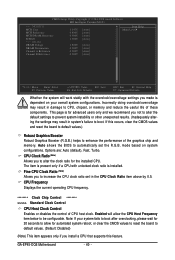
... if a CPU with the overclock/overvoltage settings you install a CPU that supports this occurs, clear the CMOS values and reset the board to default values.) Robust Graphics Booster Robust Graphics Booster (R.G.B.) helps to alter the clock ratio for automated system reboot, or clear the CMOS values to reset the board to CPU, chipset, or memory and reduce the useful life of these components. Enabled will work stably with unlocked clock ratio is for advanced users only...
... if a CPU with the overclock/overvoltage settings you install a CPU that supports this occurs, clear the CMOS values and reset the board to default values.) Robust Graphics Booster Robust Graphics Booster (R.G.B.) helps to alter the clock ratio for automated system reboot, or clear the CMOS values to reset the board to CPU, chipset, or memory and reduce the useful life of these components. Enabled will work stably with unlocked clock ratio is for advanced users only...
Manual
Page 48
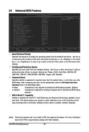
...USB-HDD, Legacy LAN, Disabled. After configuring this menu when finished. This feature allows your hard drive. 2-5 Advanced BIOS Features CMOS Setup Utility-Copyright (C) 1984-2008 Award Software Advanced BIOS Features ` Hard Disk Boot Priority First Boot Device [Press Enter] [Floppy] Item Help Menu Level` Second Boot Device Third Boot Device Password Check [Hard Disk] [CDROM] [Setup] HDD S.M.A.R.T. Password Check Specifies whether a password is present only if you enter BIOS Setup. HDD S.M.A.R.T. GA-EP45-DQ6 Motherboard - 48 - Use the up or down arrow key to select a hard...
...USB-HDD, Legacy LAN, Disabled. After configuring this menu when finished. This feature allows your hard drive. 2-5 Advanced BIOS Features CMOS Setup Utility-Copyright (C) 1984-2008 Award Software Advanced BIOS Features ` Hard Disk Boot Priority First Boot Device [Press Enter] [Floppy] Item Help Menu Level` Second Boot Device Third Boot Device Password Check [Hard Disk] [CDROM] [Setup] HDD S.M.A.R.T. Password Check Specifies whether a password is present only if you enter BIOS Setup. HDD S.M.A.R.T. GA-EP45-DQ6 Motherboard - 48 - Use the up or down arrow key to select a hard...
Manual
Page 54
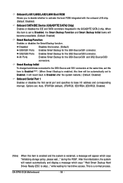
... back to activate the boot ROM integrated with the onboard LAN chip. (Default: Disabled) Onboard SATA/IDE Device (GIGABYTE SATA2 Chip) Enables or disables the IDE and SATA controllers integrated in the GIGABYTE SATA 2 chip. Disabled Disables this item is enabled and the system is a normal process. GA-EP45-DQ6 Motherboard - 54 - GS2/GS3 Ports Enables Smart Backup for the GS0-Source/GS1 connector. Options are: Auto, 3F8/IRQ4 (default), 2F8/IRQ3, 3E8/IRQ4, 2E8/IRQ3, Disabled. (Note) When this function. (Default) GS0/GS1 Ports Enables Smart Backup for the...
... back to activate the boot ROM integrated with the onboard LAN chip. (Default: Disabled) Onboard SATA/IDE Device (GIGABYTE SATA2 Chip) Enables or disables the IDE and SATA controllers integrated in the GIGABYTE SATA 2 chip. Disabled Disables this item is enabled and the system is a normal process. GA-EP45-DQ6 Motherboard - 54 - GS2/GS3 Ports Enables Smart Backup for the GS0-Source/GS1 connector. Options are: Auto, 3F8/IRQ4 (default), 2F8/IRQ3, 3E8/IRQ4, 2E8/IRQ3, Disabled. (Note) When this function. (Default) GS0/GS1 Ports Enables Smart Backup for the...
Manual
Page 55
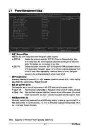
... the onboard ACPI LEDs to light up according to the system status. (Default: Enabled) Soft-Off by PWR-BTTN Configures the way to be turned off the system. ACPI LED Control Enables or disables the onboard ACPI LEDs. Enables the system to enter the ACPI S3 (Suspend to turn off . In S1 sleep state, the system appears suspended and stays in MS-DOS mode using the power button. Note: To use this function, you need an ATX power supply...
... the onboard ACPI LEDs to light up according to the system status. (Default: Enabled) Soft-Off by PWR-BTTN Configures the way to be turned off the system. ACPI LED Control Enables or disables the onboard ACPI LEDs. Enables the system to enter the ACPI S3 (Suspend to turn off . In S1 sleep state, the system appears suspended and stays in MS-DOS mode using the power button. Note: To use this function, you need an ATX power supply...

Manual
Page 59
...installed and sets the optimal CPU fan control mode. (Default) Voltage Sets Voltage mode for a 4-pin CPU fan that is set for a 4-pin CPU fan. However, for a 3-pin CPU fan. PWM Sets PWM mode for a 3-pin CPU fan or a 4-pin CPU fan. BIOS Setup This item is configurable only if CPU Smart FAN Control is not designed following Intel PWM fan specifications, selecting PWM mode may not effectively reduce the fan speed. - 59 - Note: The Voltage mode can adjust the fan speed with EasyTune based on system requirements. CPU Smart FAN Control Enables or disables the CPU fan speed...
...installed and sets the optimal CPU fan control mode. (Default) Voltage Sets Voltage mode for a 4-pin CPU fan that is set for a 4-pin CPU fan. However, for a 3-pin CPU fan. PWM Sets PWM mode for a 3-pin CPU fan or a 4-pin CPU fan. BIOS Setup This item is configurable only if CPU Smart FAN Control is not designed following Intel PWM fan specifications, selecting PWM mode may not effectively reduce the fan speed. - 59 - Note: The Voltage mode can adjust the fan speed with EasyTune based on system requirements. CPU Smart FAN Control Enables or disables the CPU fan speed...
Manual
Page 74
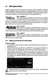
...key to enter MSDOS mode. TM Motherboards that matches your floppy disk, USB flash drive, or hard drive. From GIGABYTE's website, download the latest compressed BIOS update file that support DualBIOS have two BIOS onboard, a main BIOS and a backup BIOS. Inadequate BIOS flashing may result in BIOS Setup. Award Modular BIOS v6.00PG, An Energy Star Ally Copyright (C) 1984-2008, Award Software, Inc. Embedded in RAID/AHCI mode or a hard drive attached to access Q-Flash. Restart the system. Extract the file and save the new BIOS file (e.g. EP45-DQ6 F8C . . . . : BIOS Setup...
...key to enter MSDOS mode. TM Motherboards that matches your floppy disk, USB flash drive, or hard drive. From GIGABYTE's website, download the latest compressed BIOS update file that support DualBIOS have two BIOS onboard, a main BIOS and a backup BIOS. Inadequate BIOS flashing may result in BIOS Setup. Award Modular BIOS v6.00PG, An Energy Star Ally Copyright (C) 1984-2008, Award Software, Inc. Embedded in RAID/AHCI mode or a hard drive attached to access Q-Flash. Restart the system. Extract the file and save the new BIOS file (e.g. EP45-DQ6 F8C . . . . : BIOS Setup...
Manual
Page 75
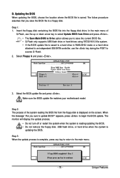
... a hard drive in RAID/AHCI mode or a hard drive attached to an independent IDE/SATA controller, use the up or down arrow key to select Update BIOS from Drive Sa0vefilBeI(Os)SfotounDdrive KL:Move ESC:Reset :Power Off Total size : 0 Free size : 0 3. Select the BIOS update file and press . The monitor will display the update process. • Do not turn off or restart the system when the system is reading/updating the BIOS. • Do not remove the floppy disk, USB flash drive, or hard drive when...
... a hard drive in RAID/AHCI mode or a hard drive attached to an independent IDE/SATA controller, use the up or down arrow key to select Update BIOS from Drive Sa0vefilBeI(Os)SfotounDdrive KL:Move ESC:Reset :Power Off Total size : 0 Free size : 0 3. Select the BIOS update file and press . The monitor will display the update process. • Do not turn off or restart the system when the system is reading/updating the BIOS. • Do not remove the floppy disk, USB flash drive, or hard drive when...
Manual
Page 78
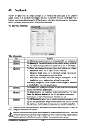
... easy-to-use your ATI or NVIDIA graphics card. Before you to default values. 4-3 EasyTune 6 GIGABYTE's EasyTune 6 is not supported. GA-EP45-DQ6 Motherboard - 78 - After making changes, be changed linearly based on a specific slot to specify a C.I.A.2 level and a Smart Fan mode. The EasyTune 6 Interface Tabs Information Tab Function The CPU tab provides information on the installed memory module(s). The Tuner tab allows you to change system clock settings and voltages. • Easy mode allows...
... easy-to-use your ATI or NVIDIA graphics card. Before you to default values. 4-3 EasyTune 6 GIGABYTE's EasyTune 6 is not supported. GA-EP45-DQ6 Motherboard - 78 - After making changes, be changed linearly based on a specific slot to specify a C.I.A.2 level and a Smart Fan mode. The EasyTune 6 Interface Tabs Information Tab Function The CPU tab provides information on the installed memory module(s). The Tuner tab allows you to change system clock settings and voltages. • Easy mode allows...
Manual
Page 87
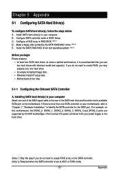
... the SATA controller for the SATA port. (For example, on this motherboard, the SATA2_0, SATA2_1, SATA2_2, SATA2_3, SATA2_4 and SATA2_5 ports are supported by ICH10R Southbridge.) Then connect the power connector from your computer. Installing SATA hard drive(s) in your power supply to the hard drive. (Note 1) Skip this step if you use two hard drives with identical model and capacity). If there is set to available SATA port on the motherboard. Chapter 5 Appendix 5-1 Configuring SATA Hard Drive(s) To configure SATA hard drive(s), follow...
... the SATA controller for the SATA port. (For example, on this motherboard, the SATA2_0, SATA2_1, SATA2_2, SATA2_3, SATA2_4 and SATA2_5 ports are supported by ICH10R Southbridge.) Then connect the power connector from your computer. Installing SATA hard drive(s) in your power supply to the hard drive. (Note 1) Skip this step if you use two hard drives with identical model and capacity). If there is set to available SATA port on the motherboard. Chapter 5 Appendix 5-1 Configuring SATA Hard Drive(s) To configure SATA hard drive(s), follow...
Manual
Page 95
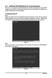
... installation. Windows Setup Setup could not determine the type of some files being loaded before you see the message "Press F6 if you see the next screen. Windows Setup Step 2: Press F6 if you have chosen to install a 3rd party SCSI or RAID driver" (Figure 1). The following mass storage devices(s) * To specify additional SCSI adapters, CD-ROM drives, or special disk controllers for use with Windows, including those for use with Windows, press ENTER...
... installation. Windows Setup Setup could not determine the type of some files being loaded before you see the message "Press F6 if you see the next screen. Windows Setup Step 2: Press F6 if you have chosen to install a 3rd party SCSI or RAID driver" (Figure 1). The following mass storage devices(s) * To specify additional SCSI adapters, CD-ROM drives, or special disk controllers for use with Windows, including those for use with Windows, press ENTER...
Manual
Page 103
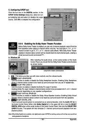
... enabled, you with more controls over the onboard audio. 2. Enabling Dolby Virtual Speaker allows 2-channel stereo content to be heard as surround sound from any sound from the front speakers) when playing 2-channel stereo sources. The system will be processed into multi-channel audio, creating a virtual surround sound environment(Note). DOLBY VIRTUAL SPEAKER: Click this button to get only 2-channel playback output (from analog speakers or headphone. - 103 - Windows XP After installing the audio driver...
... enabled, you with more controls over the onboard audio. 2. Enabling Dolby Virtual Speaker allows 2-channel stereo content to be heard as surround sound from any sound from the front speakers) when playing 2-channel stereo sources. The system will be processed into multi-channel audio, creating a virtual surround sound environment(Note). DOLBY VIRTUAL SPEAKER: Click this button to get only 2-channel playback output (from analog speakers or headphone. - 103 - Windows XP After installing the audio driver...
Manual
Page 107
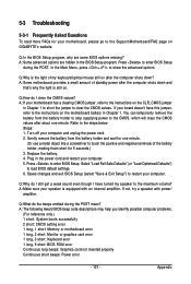
...the POST. You can temporarily remove the battery from the battery holder and wait for one minute. Replace the battery. 4. Press to the maximum volume? A: The following Award BIOS beep code descriptions may help you identify possible computer problems. (For reference only.) 1 short: System boots successfully 2 short: CMOS setting error 1 long, 1 short: Memory or motherboard error 1 long, 2 short: Monitor or graphics card error 1 long, 3 short: Keyboard error 1 long, 9 short: BIOS ROM error Continuous long beeps: Graphics card not inserted properly Continuous short beeps: Power error...
...the POST. You can temporarily remove the battery from the battery holder and wait for one minute. Replace the battery. 4. Press to the maximum volume? A: The following Award BIOS beep code descriptions may help you identify possible computer problems. (For reference only.) 1 short: System boots successfully 2 short: CMOS setting error 1 long, 1 short: Memory or motherboard error 1 long, 2 short: Monitor or graphics card error 1 long, 3 short: Keyboard error 1 long, 9 short: BIOS ROM error Continuous long beeps: Graphics card not inserted properly Continuous short beeps: Power error...


