Manual
Page 1
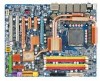
GA-EP45-DQ6 LGA775 socket motherboard for Intel® CoreTM processor family/ Intel® Pentium® processor family/Intel® Celeron® processor family User's Manual Rev. 1004 12ME-EP45DQ6-1004R
GA-EP45-DQ6 LGA775 socket motherboard for Intel® CoreTM processor family/ Intel® Pentium® processor family/Intel® Celeron® processor family User's Manual Rev. 1004 12ME-EP45DQ6-1004R
Manual
Page 2
Motherboard GA-EP45-DQ6 May 15, 2008 Motherboard GA-EP45-DQ6 May 15, 2008
Motherboard GA-EP45-DQ6 May 15, 2008 Motherboard GA-EP45-DQ6 May 15, 2008
Manual
Page 4
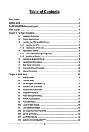
Table of Contents Box Contents ...6 OptionalItems ...6 GA-EP45-DQ6 Motherboard Layout 7 Block Diagram ...8 Chapter 1 Hardware Installation 9 1-1 Installation Precautions 9 1-2 Product Specifications 10 1-3 Installing the CPU and CPU Cooler 13 1-3-1 Installing the CPU 13 1-3-2 Installing the ...
Table of Contents Box Contents ...6 OptionalItems ...6 GA-EP45-DQ6 Motherboard Layout 7 Block Diagram ...8 Chapter 1 Hardware Installation 9 1-1 Installation Precautions 9 1-2 Product Specifications 10 1-3 Installing the CPU and CPU Cooler 13 1-3-1 Installing the CPU 13 1-3-2 Installing the ...
Manual
Page 6
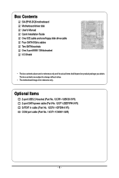
... power cable (Part No. 12CF1-2SERPW-01R) S/PDIF in cable (Part No. 12CR1-1SPDIN-01R) COM port cable (Part No. 12CF1-1CM001-32R) - 6 - Box Contents GA-EP45-DQ6 motherboard Motherboard driver disk User's Manual Quick Installation Guide One IDE cable and one floppy disk drive cable Four SATA 3Gb/s cables Two SATA brackets...
... power cable (Part No. 12CF1-2SERPW-01R) S/PDIF in cable (Part No. 12CR1-1SPDIN-01R) COM port cable (Part No. 12CF1-1CM001-32R) - 6 - Box Contents GA-EP45-DQ6 motherboard Motherboard driver disk User's Manual Quick Installation Guide One IDE cable and one floppy disk drive cable Four SATA 3Gb/s cables Two SATA brackets...
Manual
Page 7
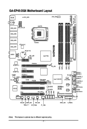
... USB_LAN2 PWR_FAN USB_LAN3 GA-EP45-DQ6 USB_LAN4 RTL8111C AUDIO RTL8111C BAT F_AUDIO PCIEX1 PE1_LED GD1 GD2 RTL8111C PCIEX16 PCIEX4_1 Intel® P45 PE_LED DDR2_1 DDR2_2 DDR2_3 DDR2_4 MD2 MD1 FDD RTL8111C CODEC PCIEX4_2 SPDIF_I CD_IN CI SPDIF_O PCI1 IT8720 PCI2 SA_LED PCIEX8 TSB43AB23 Intel® ICH10R SYS_FAN1 PCI_LED M_BIOS B_BIOS GIGABYTE SATA2 IDE SiI5723...
... USB_LAN2 PWR_FAN USB_LAN3 GA-EP45-DQ6 USB_LAN4 RTL8111C AUDIO RTL8111C BAT F_AUDIO PCIEX1 PE1_LED GD1 GD2 RTL8111C PCIEX16 PCIEX4_1 Intel® P45 PE_LED DDR2_1 DDR2_2 DDR2_3 DDR2_4 MD2 MD1 FDD RTL8111C CODEC PCIEX4_2 SPDIF_I CD_IN CI SPDIF_O PCI1 IT8720 PCI2 SA_LED PCIEX8 TSB43AB23 Intel® ICH10R SYS_FAN1 PCI_LED M_BIOS B_BIOS GIGABYTE SATA2 IDE SiI5723...
Manual
Page 10
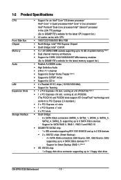
...RAID 5 and RAID 10 Š GIGABYTE SATA2 chip: - 1 x IDE connector supporting ATA-133/100/66/33 and up to 2 IDE devices Š 2 x SiI5723 chips (Smart Backup): - 4 x SATA 3Gb/s connectors (GS0-Source, GS1, GS2-Source, GS3) supporting up to 1 floppy disk drive GA-EP45-DQ6 Motherboard - 10 - Support for ... system memory (Note 1) Š Dual channel memory architecture Š Support for DDR2 1200/1066/800/667 MHz memory modules (Go to GIGABYTE's website for the latest memory support list.) Š Realtek ALC889A codec Š High Definition Audio Š 2/4/5.1/7.1-channel Š Support for...
...RAID 5 and RAID 10 Š GIGABYTE SATA2 chip: - 1 x IDE connector supporting ATA-133/100/66/33 and up to 2 IDE devices Š 2 x SiI5723 chips (Smart Backup): - 4 x SATA 3Gb/s connectors (GS0-Source, GS1, GS2-Source, GS3) supporting up to 1 floppy disk drive GA-EP45-DQ6 Motherboard - 10 - Support for ... system memory (Note 1) Š Dual channel memory architecture Š Support for DDR2 1200/1066/800/667 MHz memory modules (Go to GIGABYTE's website for the latest memory support list.) Š Realtek ALC889A codec Š High Definition Audio Š 2/4/5.1/7.1-channel Š Support for...
Manual
Page 12
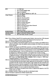
... model. (Note 8) This feature is to enable the Smart Backup function. After connecting the hard drive, be sure to enter BIOS Setup to be lost. GA-EP45-DQ6 Motherboard - 12 -
... model. (Note 8) This feature is to enable the Smart Backup function. After connecting the hard drive, be sure to enter BIOS Setup to be lost. GA-EP45-DQ6 Motherboard - 12 -
Manual
Page 14
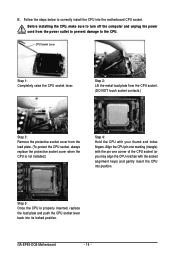
... the CPU. Step 5: Once the CPU is not installed.) Step 4: Hold the CPU with the socket alignment keys) and gently insert the CPU into position. GA-EP45-DQ6 Motherboard - 14 - CPU Socket Lever Step 1: Completely raise the CPU socket lever. Step 2: Lift the metal load plate from the CPU socket. (DO NOT touch...
... the CPU. Step 5: Once the CPU is not installed.) Step 4: Hold the CPU with the socket alignment keys) and gently insert the CPU into position. GA-EP45-DQ6 Motherboard - 14 - CPU Socket Lever Step 1: Completely raise the CPU socket lever. Step 2: Lift the metal load plate from the CPU socket. (DO NOT touch...
Manual
Page 16
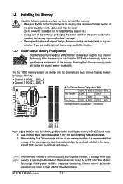
It is recommended that memory of the same capacity, brand, speed, and chips be used . (Go to GIGABYTE's website for optimum performance. After the memory is recommended that the motherboard supports the memory. DS/SS - - - - DS/SS - - When enabling Dual Channel mode with ... and capacity of different capacity and chips are unable to be installed in only one DDR2 memory module is operating in Dual Channel mode/performance. GA-EP45-DQ6 Motherboard - 16 - A memory module can be populated and remain in Flex Memory Mode will appear during the POST.
It is recommended that memory of the same capacity, brand, speed, and chips be used . (Go to GIGABYTE's website for optimum performance. After the memory is recommended that the motherboard supports the memory. DS/SS - - - - DS/SS - - When enabling Dual Channel mode with ... and capacity of different capacity and chips are unable to be installed in only one DDR2 memory module is operating in Dual Channel mode/performance. GA-EP45-DQ6 Motherboard - 16 - A memory module can be populated and remain in Flex Memory Mode will appear during the POST.
Manual
Page 18
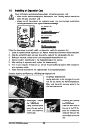
... press down on the card until it is fully inserted into the slot. 4. Turn on the card are completely inserted into the PCI Express slot. GA-EP45-DQ6 Motherboard - 18 - • Removing the Card from the power outlet before you begin to install an expansion card: • Make sure the motherboard supports the...
... press down on the card until it is fully inserted into the slot. 4. Turn on the card are completely inserted into the PCI Express slot. GA-EP45-DQ6 Motherboard - 18 - • Removing the Card from the power outlet before you begin to install an expansion card: • Make sure the motherboard supports the...
Manual
Page 20
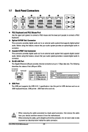
... Connectors PS/2 Keyboard and PS/2 Mouse Port Use the upper port (green) to connect a PS/2 mouse and the lower port (purple) to 1 Gbps data rate. GA-EP45-DQ6 Motherboard - 20 - RJ-45 LAN Port The Gigabit Ethernet LAN port provides Internet connection at up to connect a PS/2 keyboard. Coaxial S/PDIF Out Connector This...
... Connectors PS/2 Keyboard and PS/2 Mouse Port Use the upper port (green) to connect a PS/2 mouse and the lower port (purple) to 1 Gbps data rate. GA-EP45-DQ6 Motherboard - 20 - RJ-45 LAN Port The Gigabit Ethernet LAN port provides Internet connection at up to connect a PS/2 keyboard. Coaxial S/PDIF Out Connector This...

Manual
Page 22
... has 3 quick switches: power switch, reset switch and clearing CMOS switch, allowing users to improper plug/unplug actions. Power Switch Reset Switch Clearing CMOS Switch GA-EP45-DQ6 Motherboard - 22 - The 7 LEDs indicate if a component (including CPU and memory) or a device (including PCI and PCIe cards and IDE/SATA devices) works abnormally. 1-8 Onboard...
... has 3 quick switches: power switch, reset switch and clearing CMOS switch, allowing users to improper plug/unplug actions. Power Switch Reset Switch Clearing CMOS Switch GA-EP45-DQ6 Motherboard - 22 - The 7 LEDs indicate if a component (including CPU and memory) or a device (including PCI and PCIe cards and IDE/SATA devices) works abnormally. 1-8 Onboard...

Manual
Page 24
... (Only for 2x4 pin 12V) 3 GND 4 GND 5 +12V (Only for 2x4 pin 12V) 6 +12V (Only for 2x4 pin 12V) 7 +12V 8 +12V 12 24 1 13 ATX GA-EP45-DQ6 Motherboard ATX: Pin No. 1 2 3 4 5 6 7 8 9 10 11 12 Definition Pin No. 3.3V 13 3.3V 14 GND 15 +5V 16 GND 17 +5V 18 GND 19 Power...
... (Only for 2x4 pin 12V) 3 GND 4 GND 5 +12V (Only for 2x4 pin 12V) 6 +12V (Only for 2x4 pin 12V) 7 +12V 8 +12V 12 24 1 13 ATX GA-EP45-DQ6 Motherboard ATX: Pin No. 1 2 3 4 5 6 7 8 9 10 11 12 Definition Pin No. 3.3V 13 3.3V 14 GND 15 +5V 16 GND 17 +5V 18 GND 19 Power...
Manual
Page 26
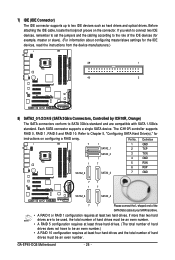
The ICH10R controller supports RAID 0, RAID 1, RAID 5 and RAID 10. GA-EP45-DQ6 Motherboard - 26 - 7) IDE (IDE Connector) The IDE connector supports up to SATA 3Gb/s standard and are compatible with SATA 1.5Gb/s standard. Each SATA connector supports a ...
The ICH10R controller supports RAID 0, RAID 1, RAID 5 and RAID 10. GA-EP45-DQ6 Motherboard - 26 - 7) IDE (IDE Connector) The IDE connector supports up to SATA 3Gb/s standard and are compatible with SATA 1.5Gb/s standard. Each SATA connector supports a ...
Manual
Page 28
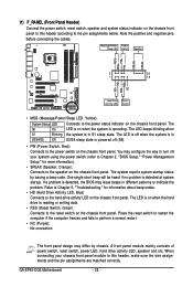
...; HD (Hard Drive Activity LED, Blue) Connects to the speaker on when the system is detected, the BIOS may issue beeps in S1 sleep state. GA-EP45-DQ6 Motherboard - 28 - The LED is on when the hard drive is on the chassis front panel. 11) F_PANEL (Front Panel Header) Connect the power switch...
...; HD (Hard Drive Activity LED, Blue) Connects to the speaker on when the system is detected, the BIOS may issue beeps in S1 sleep state. GA-EP45-DQ6 Motherboard - 28 - The LED is on when the hard drive is on the chassis front panel. 11) F_PANEL (Front Panel Header) Connect the power switch...
Manual
Page 30
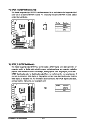
... audio cable for digital audio output from your motherboard to your motherboard to certain expansion cards like graphics cards and sound cards. Definition 1 1 SPDIFO 2 GND GA-EP45-DQ6 Motherboard - 30 - 14) SPDIF_I (S/PDIF In Header, Red) This header supports digital S/PDIF in and can connect to the graphics card and have digital audio...
... audio cable for digital audio output from your motherboard to your motherboard to certain expansion cards like graphics cards and sound cards. Definition 1 1 SPDIFO 2 GND GA-EP45-DQ6 Motherboard - 30 - 14) SPDIF_I (S/PDIF In Header, Red) This header supports digital S/PDIF in and can connect to the graphics card and have digital audio...
Manual
Page 32
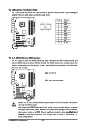
date information and BIOS configurations) and reset the CMOS values to clear the CMOS values (e.g. GA-EP45-DQ6 Motherboard - 32 - To clear the CMOS values, place a jumper cap on your computer and unplug the power cord from the jumper. Open: Normal Short: Clear ...
date information and BIOS configurations) and reset the CMOS values to clear the CMOS values (e.g. GA-EP45-DQ6 Motherboard - 32 - To clear the CMOS values, place a jumper cap on your computer and unplug the power cord from the jumper. Open: Normal Short: Clear ...

Manual
Page 34
22) PHASE LED The number of lighted LEDs. The higher the CPU loading, the more the number of lighted LEDs indicates the CPU loading. GA-EP45-DQ6 Motherboard - 34 -
22) PHASE LED The number of lighted LEDs. The higher the CPU loading, the more the number of lighted LEDs indicates the CPU loading. GA-EP45-DQ6 Motherboard - 34 -
Manual
Page 36
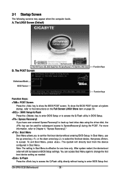
... access the Q-Flash utility in Boot Menu is effective for subsequent access to set the first boot device without having to accept. GA-EP45-DQ6 Motherboard - 36 - The system will still be used for one time only. A. The POST Screen Award Modular BIOS v6.00PG...the device configured in Boot Menu. The LOGO Screen (Default) :POST Screen :BIOS Setup/Q-Flash :XpressRecovery2 :Boot Menu :Qflash B. Motherboard Model BIOS Version EP45-DQ6 F8C . . . . : BIOS Setup : XpressRecovery2 : Boot Menu : Qflash 07/01/2008-P45-ICH10-7A89PG06C-00 Function Keys Function Keys Function Keys:...
... access the Q-Flash utility in Boot Menu is effective for subsequent access to set the first boot device without having to accept. GA-EP45-DQ6 Motherboard - 36 - The system will still be used for one time only. A. The POST Screen Award Modular BIOS v6.00PG...the device configured in Boot Menu. The LOGO Screen (Default) :POST Screen :BIOS Setup/Q-Flash :XpressRecovery2 :Boot Menu :Qflash B. Motherboard Model BIOS Version EP45-DQ6 F8C . . . . : BIOS Setup : XpressRecovery2 : Boot Menu : Qflash 07/01/2008-P45-ICH10-7A89PG06C-00 Function Keys Function Keys Function Keys:...
Manual
Page 38
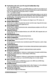
... to restrict access to the system and BIOS Setup. A supervisor password allows you to view the BIOS settings but not to make changes in effect. GA-EP45-DQ6 Motherboard - 38 - It allows you to restrict access to the system and BIOS Setup. You can create up to 8 profiles (Profile 1-8) and name each profile...
... to restrict access to the system and BIOS Setup. A supervisor password allows you to view the BIOS settings but not to make changes in effect. GA-EP45-DQ6 Motherboard - 38 - It allows you to restrict access to the system and BIOS Setup. You can create up to 8 profiles (Profile 1-8) and name each profile...
