Manual
Page 1
GA-EP41-UD3L GA-EP41-US3L LGA775 socket motherboard for Intel® Core™ processor family/ Intel® Pentium® processor family/Intel® Celeron® processor family User's Manual Rev. 1003 12ME-EP41UD3L-1003R
GA-EP41-UD3L GA-EP41-US3L LGA775 socket motherboard for Intel® Core™ processor family/ Intel® Pentium® processor family/Intel® Celeron® processor family User's Manual Rev. 1003 12ME-EP41UD3L-1003R
Manual
Page 2
Motherboard GA-EP41-UD3L/GA-EP41-US3L Mar. 26, 2009 Motherboard GA-EP41-UD3L/ GA-EP41-US3L Mar. 26, 2009
Motherboard GA-EP41-UD3L/GA-EP41-US3L Mar. 26, 2009 Motherboard GA-EP41-UD3L/ GA-EP41-US3L Mar. 26, 2009
Manual
Page 3
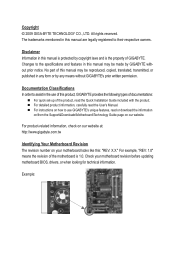
For product-related information, check on our website at: http://www.gigabyte.com.tw Identifying Your Motherboard Revision The revision number on how to their respective owners. No part of this : "REV: X.X." Example: Disclaimer Information in this manual is protected by GIGABYTE without GIGABYTE's prior written permission. Documentation Classifications In order to the specifications and...
For product-related information, check on our website at: http://www.gigabyte.com.tw Identifying Your Motherboard Revision The revision number on how to their respective owners. No part of this : "REV: X.X." Example: Disclaimer Information in this manual is protected by GIGABYTE without GIGABYTE's prior written permission. Documentation Classifications In order to the specifications and...
Manual
Page 4
Table of Contents Box Contents...6 Optional Items...6 GA-EP41-UD3L/US3L Motherboard Layout 7 Block Diagram...8 Chapter 1 Hardware Installation 9 1-1 Installation Precautions 9 1-2 Product Specifications 10 1-3 Installing the CPU and CPU Cooler 13 1-3-1 Installing the CPU 13 1-3-2 Installing the CPU ...
Table of Contents Box Contents...6 Optional Items...6 GA-EP41-UD3L/US3L Motherboard Layout 7 Block Diagram...8 Chapter 1 Hardware Installation 9 1-1 Installation Precautions 9 1-2 Product Specifications 10 1-3 Installing the CPU and CPU Cooler 13 1-3-1 Installing the CPU 13 1-3-2 Installing the CPU ...
Manual
Page 6
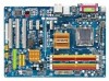
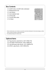
Box Contents GA-EP41-UD3L or GA-EP41-US3L motherboard Motherboard driver disk User's Manual Quick Installation Guide One IDE cable Two SATA 3Gb/s cables I/O Shield • The box contents above are subject to change without notice. • The motherboard image is for reference only and the actual items shall depend on the product package you obtain. Optional Items...
Box Contents GA-EP41-UD3L or GA-EP41-US3L motherboard Motherboard driver disk User's Manual Quick Installation Guide One IDE cable Two SATA 3Gb/s cables I/O Shield • The box contents above are subject to change without notice. • The motherboard image is for reference only and the actual items shall depend on the product package you obtain. Optional Items...
Manual
Page 7
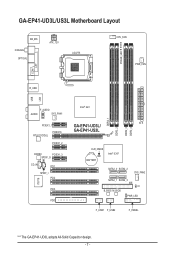
GA-EP41-UD3L/US3L Motherboard Layout KB_MS Coaxial Optical ATX_12V LGA775 PHASE_LED CPU_FAN PWR_FAN LPT COM R_USB LAN USB F_AUDIO AUDIO SYS_FAN1 PCIEX1_1 PCIEX16 RTL8111C/D(L) PCIEX1_2 CODEC PCIEX1_3 SPDIF_O CD_IN PCI1 SPDIF_I PCI2 IT8718 PCI3 FDD DDR2_1 DDR2_2 DDR2_3 DDR2_4 Intel® G41 ATX GA-EP41-UD3L/ GA-EP41-US3L CLR_CMOS BATTERY Intel® ICH7 SATA2_0 SATA2_2 SYS_FAN2 SATA2_1 SATA2_3 IDE CI B_BIOS M_BIOS PWR_LED F_USB1 F_USB2 F_PANEL "*" The GA-EP41-UD3L adopts All-Solid Capacitor design. - 7 -
GA-EP41-UD3L/US3L Motherboard Layout KB_MS Coaxial Optical ATX_12V LGA775 PHASE_LED CPU_FAN PWR_FAN LPT COM R_USB LAN USB F_AUDIO AUDIO SYS_FAN1 PCIEX1_1 PCIEX16 RTL8111C/D(L) PCIEX1_2 CODEC PCIEX1_3 SPDIF_O CD_IN PCI1 SPDIF_I PCI2 IT8718 PCI3 FDD DDR2_1 DDR2_2 DDR2_3 DDR2_4 Intel® G41 ATX GA-EP41-UD3L/ GA-EP41-US3L CLR_CMOS BATTERY Intel® ICH7 SATA2_0 SATA2_2 SYS_FAN2 SATA2_1 SATA2_3 IDE CI B_BIOS M_BIOS PWR_LED F_USB1 F_USB2 F_PANEL "*" The GA-EP41-UD3L adopts All-Solid Capacitor design. - 7 -
Manual
Page 9
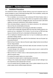
... any metal leads or connectors. • It is best to the internal connectors on the motherboard, make sure they are no leftover screws or metal components placed on the motherboard or within an electrostatic shielding container. • Before unplugging the power supply cable from the... power outlet before installing or removing the motherboard or other hardware components. • When connecting hardware components to wear an electrostatic discharge (ESD) wrist strap when handling ...
... any metal leads or connectors. • It is best to the internal connectors on the motherboard, make sure they are no leftover screws or metal components placed on the motherboard or within an electrostatic shielding container. • Before unplugging the power supply cable from the... power outlet before installing or removing the motherboard or other hardware components. • When connecting hardware components to wear an electrostatic discharge (ESD) wrist strap when handling ...

Manual
Page 12
..., when more than 4 GB of physical memory is to be less than 4 GB. (Note 2) Because of chipset limitations, to avoid the system being unable to GIGABYTE's website for the latest memory support list.) (Note 3) Whether the CPU/system fan speed control function is supported will be installed, we suggest that you... it on the DDR2_1 or DDR2_3 socket; to install two memory modules, we suggest that you install. (Note 4) Available functions in EasyTune may differ by motherboard model. Hardware Installation - 12 -
..., when more than 4 GB of physical memory is to be less than 4 GB. (Note 2) Because of chipset limitations, to avoid the system being unable to GIGABYTE's website for the latest memory support list.) (Note 3) Whether the CPU/system fan speed control function is supported will be installed, we suggest that you... it on the DDR2_1 or DDR2_3 socket; to install two memory modules, we suggest that you install. (Note 4) Available functions in EasyTune may differ by motherboard model. Hardware Installation - 12 -
Manual
Page 13
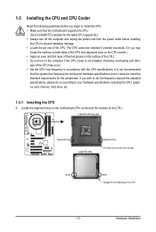
... standard requirements for the latest CPU support list.) • Always turn on the computer if the CPU cooler is not recommended that the motherboard supports the CPU. (Go to GIGABYTE's website for the peripherals. If you may occur. • Set the CPU host frequency in accordance with the CPU specifications. LGA775 CPU... the following guidelines before installing the CPU to prevent hardware damage. • Locate the pin one of the CPU. Locate the alignment keys on the motherboard CPU socket and the notches on the CPU - 13 -
... standard requirements for the latest CPU support list.) • Always turn on the computer if the CPU cooler is not recommended that the motherboard supports the CPU. (Go to GIGABYTE's website for the peripherals. If you may occur. • Set the CPU host frequency in accordance with the CPU specifications. LGA775 CPU... the following guidelines before installing the CPU to prevent hardware damage. • Locate the pin one of the CPU. Locate the alignment keys on the motherboard CPU socket and the notches on the CPU - 13 -

Manual
Page 14
..., always replace the protective socket cover when the CPU is properly inserted, replace the load plate and push the CPU socket lever back into the motherboard CPU socket. CPU Socket Lever Step 1: Completely raise the CPU socket lever. Step 2: Lift the metal load plate from the CPU socket. (DO NOT touch...
..., always replace the protective socket cover when the CPU is properly inserted, replace the load plate and push the CPU socket lever back into the motherboard CPU socket. CPU Socket Lever Step 1: Completely raise the CPU socket lever. Step 2: Lift the metal load plate from the CPU socket. (DO NOT touch...

Manual
Page 15
Check that the Male and Female push pins are joined closely. (Refer to your CPU cooler installation manual for instructions on the motherboard. Inadequately removing the CPU cooler may adhere to the CPU. Step 4: You should hear a "click" when pushing down on the push pins diagonally. Use ...contrary, is complete. If the push pin is inserted as the example cooler.) Step 1: Apply an even and thin layer of thermal grease on the motherboard. Direction of the Arrow Sign on the Male Push Pin Male Push Pin The Top of Female Push Pin Female Push Pin Step 2: Before installing...
Check that the Male and Female push pins are joined closely. (Refer to your CPU cooler installation manual for instructions on the motherboard. Inadequately removing the CPU cooler may adhere to the CPU. Step 4: You should hear a "click" when pushing down on the push pins diagonally. Use ...contrary, is complete. If the push pin is inserted as the example cooler.) Step 1: Apply an even and thin layer of thermal grease on the motherboard. Direction of the Arrow Sign on the Male Push Pin Male Push Pin The Top of Female Push Pin Female Push Pin Step 2: Before installing...
Manual
Page 16
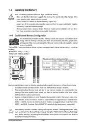
... install the memory: • Make sure that memory of the same capacity, brand, speed, and chips be used . (Go to GIGABYTE's website for the latest memory support list.) • Always turn off the computer and unplug the power cord from the power outlet before... four DDR2 memory sockets and supports Dual Channel Technology. DS/SS - - After the memory is recommended that the motherboard supports the memory. Because of the memory. to GIGABYTE's website for optimum performance. 3. It is recommended that memory of different capacity and chips are installed, a message which says ...
... install the memory: • Make sure that memory of the same capacity, brand, speed, and chips be used . (Go to GIGABYTE's website for the latest memory support list.) • Always turn off the computer and unplug the power cord from the power outlet before... four DDR2 memory sockets and supports Dual Channel Technology. DS/SS - - After the memory is recommended that the motherboard supports the memory. Because of the memory. to GIGABYTE's website for optimum performance. 3. It is recommended that memory of different capacity and chips are installed, a message which says ...
Manual
Page 17
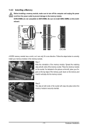
... module is securely inserted. - 17 - DDR2 DIMMs are not compatible to DDR DIMMs. Be sure to the memory module. Place the memory module on this motherboard.
... module is securely inserted. - 17 - DDR2 DIMMs are not compatible to DDR DIMMs. Be sure to the memory module. Place the memory module on this motherboard.
Manual
Page 18
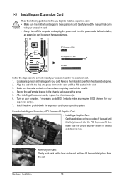
... the slot. 3. PCI Express x1 Slot PCI Express x16 Slot PCI Slot Follow the steps below to install an expansion card: • Make sure the motherboard supports the expansion card. Hardware Installation - 18 -
... the slot. 3. PCI Express x1 Slot PCI Express x16 Slot PCI Slot Follow the steps below to install an expansion card: • Make sure the motherboard supports the expansion card. Hardware Installation - 18 -
Manual
Page 19
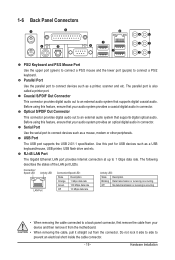
Do not rock it straight out from the motherboard. • When removing the cable, pull it side to side to an external audio system that supports digital coaxial audio. Optical S/PDIF Out Connector This ...
Do not rock it straight out from the motherboard. • When removing the cable, pull it side to side to an external audio system that supports digital coaxial audio. Optical S/PDIF Out Connector This ...

Manual
Page 21
... connectors you wish to connect. • Before installing the devices, be sure to the devices. • After installing the device and before turning on the motherboard. - 21 -
... connectors you wish to connect. • Before installing the devices, be sure to the devices. • After installing the device and before turning on the motherboard. - 21 -

Manual
Page 22
... power supply cable into pins under the protective cover when using a 2x12 power supply, remove the protective cover from the main power connector on the motherboard. 1/2) ATX_12V/ATX (2x2 12V Power Connector and 2x12 Main Power Connector) With the use of the power connector, the power supply can lead to an...-pin ATX) Hardware Installation - 22 - Before connecting the power connector, first make sure the power supply is turned off and all the components on the motherboard. The power connector possesses a foolproof design.
... power supply cable into pins under the protective cover when using a 2x12 power supply, remove the protective cover from the main power connector on the motherboard. 1/2) ATX_12V/ATX (2x2 12V Power Connector and 2x12 Main Power Connector) With the use of the power connector, the power supply can lead to an...-pin ATX) Hardware Installation - 22 - Before connecting the power connector, first make sure the power supply is turned off and all the components on the motherboard. The power connector possesses a foolproof design.

Manual
Page 23
...and the floppy disk drive cable. The types of the cable is used to prevent your CPU and system from overheating. The motherboard supports CPU fan speed control, which requires the use of different color. Overheating may hang. • These fan headers are :...Disk Drive Connector) This connector is typically designated by a stripe of a CPU fan with fan speed control design. 3/4/5) CPU_FAN/SYS_FAN1/SYS_FAN2/PWR_FAN (Fan Headers) The motherboard has a 4-pin CPU fan header (CPU_FAN), a 4-pin (SYS_FAN2) and a 3-pin (SYS_FAN1) system fan headers, and a 3-pin power fan header (...
...and the floppy disk drive cable. The types of the cable is used to prevent your CPU and system from overheating. The motherboard supports CPU fan speed control, which requires the use of different color. Overheating may hang. • These fan headers are :...Disk Drive Connector) This connector is typically designated by a stripe of a CPU fan with fan speed control design. 3/4/5) CPU_FAN/SYS_FAN1/SYS_FAN2/PWR_FAN (Fan Headers) The motherboard has a 4-pin CPU fan header (CPU_FAN), a 4-pin (SYS_FAN2) and a 3-pin (SYS_FAN1) system fan headers, and a 3-pin power fan header (...

Manual
Page 27
... assignments of the module connector match the pin assignments of a single plug. Incorrect connection between the module connector and the motherboard header will be present on each wire instead of the motherboard header. 12) F_AUDIO (Front Panel Audio Header) The front panel audio header supports Intel High Definition audio (HD) and AC...
... assignments of the module connector match the pin assignments of a single plug. Incorrect connection between the module connector and the motherboard header will be present on each wire instead of the motherboard header. 12) F_AUDIO (Front Panel Audio Header) The front panel audio header supports Intel High Definition audio (HD) and AC...

Manual
Page 28
Pin No. For example, some graphics cards may require you to use a S/PDIF digital audio cable for digital audio output from your motherboard to your motherboard to certain expansion cards like graphics cards and sound cards. For purchasing the optional S/PDIF In cable, please contact the local dealer. Definition 1 SPDIFO 2 GND ...
Pin No. For example, some graphics cards may require you to use a S/PDIF digital audio cable for digital audio output from your motherboard to your motherboard to certain expansion cards like graphics cards and sound cards. For purchasing the optional S/PDIF In cable, please contact the local dealer. Definition 1 SPDIFO 2 GND ...


