Manual
Page 1
GA-EP41-UD3L GA-EP41-US3L LGA775 socket motherboard for Intel® Core™ processor family/ Intel® Pentium® processor family/Intel® Celeron® processor family User's Manual Rev. 1003 12ME-EP41UD3L-1003R
GA-EP41-UD3L GA-EP41-US3L LGA775 socket motherboard for Intel® Core™ processor family/ Intel® Pentium® processor family/Intel® Celeron® processor family User's Manual Rev. 1003 12ME-EP41UD3L-1003R
Manual
Page 2
Motherboard GA-EP41-UD3L/GA-EP41-US3L Mar. 26, 2009 Motherboard GA-EP41-UD3L/ GA-EP41-US3L Mar. 26, 2009
Motherboard GA-EP41-UD3L/GA-EP41-US3L Mar. 26, 2009 Motherboard GA-EP41-UD3L/ GA-EP41-US3L Mar. 26, 2009
Manual
Page 3
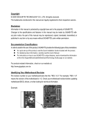
... this manual may be made by any form or by GIGABYTE without GIGABYTE's prior written permission. For detailed product information, carefully read or download the information on/from the Support&Downloads\Motherboard\Technology Guide page on our website. Example: For example,... reserved. Disclaimer Information in this product, GIGABYTE provides the following types of documentations: For quick set-up of GIGABYTE. For product-related information, check on our website at: http://www.gigabyte.com.tw Identifying Your Motherboard Revision The revision number on how to...
... this manual may be made by any form or by GIGABYTE without GIGABYTE's prior written permission. For detailed product information, carefully read or download the information on/from the Support&Downloads\Motherboard\Technology Guide page on our website. Example: For example,... reserved. Disclaimer Information in this product, GIGABYTE provides the following types of documentations: For quick set-up of GIGABYTE. For product-related information, check on our website at: http://www.gigabyte.com.tw Identifying Your Motherboard Revision The revision number on how to...
Manual
Page 4
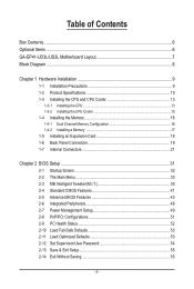
Table of Contents Box Contents...6 Optional Items...6 GA-EP41-UD3L/US3L Motherboard Layout 7 Block Diagram...8 Chapter 1 Hardware Installation 9 1-1 Installation Precautions 9 1-2 Product Specifications 10 1-3 Installing the CPU and CPU Cooler 13 1-3-1 Installing the CPU 13 1-3-2 Installing the CPU ...
Table of Contents Box Contents...6 Optional Items...6 GA-EP41-UD3L/US3L Motherboard Layout 7 Block Diagram...8 Chapter 1 Hardware Installation 9 1-1 Installation Precautions 9 1-2 Product Specifications 10 1-3 Installing the CPU and CPU Cooler 13 1-3-1 Installing the CPU 13 1-3-2 Installing the CPU ...
Manual
Page 6
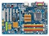
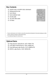
Box Contents GA-EP41-UD3L or GA-EP41-US3L motherboard Motherboard driver disk User's Manual Quick Installation Guide One IDE cable Two SATA 3Gb/s cables I/O Shield • The box contents above are subject to change without notice. • The motherboard image is for reference only and the actual items shall depend on the product package you obtain. The box...
Box Contents GA-EP41-UD3L or GA-EP41-US3L motherboard Motherboard driver disk User's Manual Quick Installation Guide One IDE cable Two SATA 3Gb/s cables I/O Shield • The box contents above are subject to change without notice. • The motherboard image is for reference only and the actual items shall depend on the product package you obtain. The box...
Manual
Page 7
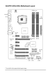
GA-EP41-UD3L/US3L Motherboard Layout KB_MS Coaxial Optical ATX_12V LGA775 PHASE_LED CPU_FAN PWR_FAN LPT COM R_USB LAN USB F_AUDIO AUDIO SYS_FAN1 PCIEX1_1 PCIEX16 RTL8111C/D(L) PCIEX1_2 CODEC PCIEX1_3 SPDIF_O CD_IN PCI1 SPDIF_I PCI2 IT8718 PCI3 FDD DDR2_1 DDR2_2 DDR2_3 DDR2_4 Intel® G41 ATX GA-EP41-UD3L/ GA-EP41-US3L CLR_CMOS BATTERY Intel® ICH7 SATA2_0 SATA2_2 SYS_FAN2 SATA2_1 SATA2_3 IDE CI B_BIOS M_BIOS PWR_LED F_USB1 F_USB2 F_PANEL "*" The GA-EP41-UD3L adopts All-Solid Capacitor design. - 7 -
GA-EP41-UD3L/US3L Motherboard Layout KB_MS Coaxial Optical ATX_12V LGA775 PHASE_LED CPU_FAN PWR_FAN LPT COM R_USB LAN USB F_AUDIO AUDIO SYS_FAN1 PCIEX1_1 PCIEX16 RTL8111C/D(L) PCIEX1_2 CODEC PCIEX1_3 SPDIF_O CD_IN PCI1 SPDIF_I PCI2 IT8718 PCI3 FDD DDR2_1 DDR2_2 DDR2_3 DDR2_4 Intel® G41 ATX GA-EP41-UD3L/ GA-EP41-US3L CLR_CMOS BATTERY Intel® ICH7 SATA2_0 SATA2_2 SYS_FAN2 SATA2_1 SATA2_3 IDE CI B_BIOS M_BIOS PWR_LED F_USB1 F_USB2 F_PANEL "*" The GA-EP41-UD3L adopts All-Solid Capacitor design. - 7 -
Manual
Page 9
...an ESD wrist strap, keep your hands dry and first touch a metal object to eliminate static electricity. • Prior to installing the motherboard, please have a problem related to the local voltage standard. • Before using the product, please verify that all cables and power...components. • When connecting hardware components to the internal connectors on the computer power during the installation process can become damaged as a motherboard, CPU or memory. Prior to installation, carefully read the user's manual and follow these procedures: • Prior to installation, do...
...an ESD wrist strap, keep your hands dry and first touch a metal object to eliminate static electricity. • Prior to installing the motherboard, please have a problem related to the local voltage standard. • Before using the product, please verify that all cables and power...components. • When connecting hardware components to the internal connectors on the computer power during the installation process can become damaged as a motherboard, CPU or memory. Prior to installation, carefully read the user's manual and follow these procedures: • Prior to installation, do...

Manual
Page 12
Hardware Installation - 12 - to install two memory modules, we suggest that you install them on the DDR2_1 and DDR2_3 sockets. (Go to GIGABYTE's website for Microsoft® Windows® Vista/XP w ATX Form Factor; 30.5cm x 21.0cm (Note 1) Due to Windows Vista/XP 32-bit operating system ... supported will be installed, we suggest that you install it on the CPU/system cooler you install. (Note 4) Available functions in EasyTune may differ by motherboard model.
Hardware Installation - 12 - to install two memory modules, we suggest that you install them on the DDR2_1 and DDR2_3 sockets. (Go to GIGABYTE's website for Microsoft® Windows® Vista/XP w ATX Form Factor; 30.5cm x 21.0cm (Note 1) Due to Windows Vista/XP 32-bit operating system ... supported will be installed, we suggest that you install it on the CPU/system cooler you install. (Note 4) Available functions in EasyTune may differ by motherboard model.
Manual
Page 13
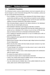
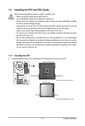
... Notch Notch Triangle Pin One Marking on the computer if the CPU cooler is not recommended that the motherboard supports the CPU. (Go to GIGABYTE's website for the peripherals. Locate the alignment keys on the motherboard CPU socket and the notches on the CPU. 1-3 Installing the CPU and CPU Cooler Read the following...
... Notch Notch Triangle Pin One Marking on the computer if the CPU cooler is not recommended that the motherboard supports the CPU. (Go to GIGABYTE's website for the peripherals. Locate the alignment keys on the motherboard CPU socket and the notches on the CPU. 1-3 Installing the CPU and CPU Cooler Read the following...

Manual
Page 14
..., always replace the protective socket cover when the CPU is properly inserted, replace the load plate and push the CPU socket lever back into the motherboard CPU socket. Hardware Installation - 14 -
..., always replace the protective socket cover when the CPU is properly inserted, replace the load plate and push the CPU socket lever back into the motherboard CPU socket. Hardware Installation - 14 -

Manual
Page 15
...removing the CPU cooler may adhere to the CPU. 1-3-2 Installing the CPU Cooler Follow the steps below to correctly install the CPU cooler on the motherboard. (The following procedure uses Intel® boxed cooler as the picture above shows, the installation is to install.) Step 3: Place the cooler atop... the CPU, aligning the four push pins through the pin holes on the motherboard. Step 4: You should hear a "click" when pushing down on the male push pin. (Turning the push pin along the direction of the installed ...
...removing the CPU cooler may adhere to the CPU. 1-3-2 Installing the CPU Cooler Follow the steps below to correctly install the CPU cooler on the motherboard. (The following procedure uses Intel® boxed cooler as the picture above shows, the installation is to install.) Step 3: Place the cooler atop... the CPU, aligning the four push pins through the pin holes on the motherboard. Step 4: You should hear a "click" when pushing down on the male push pin. (Turning the push pin along the direction of the installed ...
Manual
Page 16
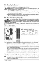
...and capacity of different capacity and chips are installed, a message which says memory is to install the memory: • Make sure that the motherboard supports the memory. DS/SS - - Hardware Installation - 16 - 1-4 Installing the Memory Read the following guidelines before installing the memory in ...Dual Channel mode/performance. Intel Flex Memory Technology offers greater flexibility to upgrade by allowing different memory sizes to be used . (Go to GIGABYTE's website for the latest memory support list.) When memory modules of the memory. DS/SS - - - - If you install them...
...and capacity of different capacity and chips are installed, a message which says memory is to install the memory: • Make sure that the motherboard supports the memory. DS/SS - - Hardware Installation - 16 - 1-4 Installing the Memory Read the following guidelines before installing the memory in ...Dual Channel mode/performance. Intel Flex Memory Technology offers greater flexibility to upgrade by allowing different memory sizes to be used . (Go to GIGABYTE's website for the latest memory support list.) When memory modules of the memory. DS/SS - - - - If you install them...
Manual
Page 17
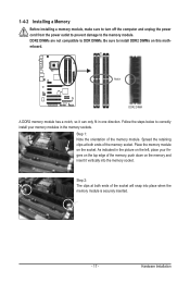
..., make sure to turn off the computer and unplug the power cord from the power outlet to prevent damage to install DDR2 DIMMs on this motherboard. Follow the steps below to correctly install your fingers on the top edge of the memory module. Hardware Installation
..., make sure to turn off the computer and unplug the power cord from the power outlet to prevent damage to install DDR2 DIMMs on this motherboard. Follow the steps below to correctly install your fingers on the top edge of the memory module. Hardware Installation
Manual
Page 18
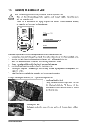
... below to make any required BIOS changes for your operating system. Secure the card's metal bracket to install an expansion card: • Make sure the motherboard supports the expansion card. After installing all expansion cards, replace the chassis cover(s). 6. Example: Installing and Removing a PCI Express x16 Graphics Card: • Installing a Graphics...
... below to make any required BIOS changes for your operating system. Secure the card's metal bracket to install an expansion card: • Make sure the motherboard supports the expansion card. After installing all expansion cards, replace the chassis cover(s). 6. Example: Installing and Removing a PCI Express x16 Graphics Card: • Installing a Graphics...
Manual
Page 19
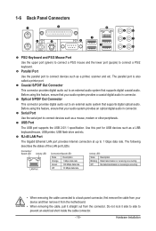
... an electrical short inside the cable connector. - 19 - Use this feature, ensure that supports digital optical audio. Do not rock it straight out from the motherboard. • When removing the cable, pull it side to side to a back panel connector, first remove the cable from your device and then remove it...
... an electrical short inside the cable connector. - 19 - Use this feature, ensure that supports digital optical audio. Do not rock it straight out from the motherboard. • When removing the cable, pull it side to side to a back panel connector, first remove the cable from your device and then remove it...

Manual
Page 21
... 12) F_AUDIO 13) CD_IN 14) SPDIF_I 15) SPDIF_O 16) F_USB1/F_USB2 17) CI 18) CLR_CMOS 19) PHASE_LED Read the following guidelines before turning on the motherboard. - 21 - Unplug the power cord from the power outlet to prevent damage to the devices. • After installing the device and before connecting external devices...
... 12) F_AUDIO 13) CD_IN 14) SPDIF_I 15) SPDIF_O 16) F_USB1/F_USB2 17) CI 18) CLR_CMOS 19) PHASE_LED Read the following guidelines before turning on the motherboard. - 21 - Unplug the power cord from the power outlet to prevent damage to the devices. • After installing the device and before connecting external devices...

Manual
Page 22
... power connector is not connected, the computer will not start. • To meet expansion requirements, it is turned off and all the components on the motherboard. Do not insert the power supply cable into pins under the protective cover when using a 2x12 power supply, remove the protective cover from the main...
... power connector is not connected, the computer will not start. • To meet expansion requirements, it is turned off and all the components on the motherboard. Do not insert the power supply cable into pins under the protective cover when using a 2x12 power supply, remove the protective cover from the main...

Manual
Page 23
...or the system may hang. • These fan headers are : 360 KB, 720 KB, 1.2 MB, 1.44 MB, and 2.88 MB. The motherboard supports CPU fan speed control, which requires the use of different color. Do not place a jumper cap on the headers. 6) FDD (Floppy Disk ... cable. For purchasing the optional floppy disk drive cable, please contact the local dealer. 33 1 34 2 - 23 - 3/4/5) CPU_FAN/SYS_FAN1/SYS_FAN2/PWR_FAN (Fan Headers) The motherboard has a 4-pin CPU fan header (CPU_FAN), a 4-pin (SYS_FAN2) and a 3-pin (SYS_FAN1) system fan headers, and a 3-pin power fan header (PWR_FAN). Hardware ...
...or the system may hang. • These fan headers are : 360 KB, 720 KB, 1.2 MB, 1.44 MB, and 2.88 MB. The motherboard supports CPU fan speed control, which requires the use of different color. Do not place a jumper cap on the headers. 6) FDD (Floppy Disk ... cable. For purchasing the optional floppy disk drive cable, please contact the local dealer. 33 1 34 2 - 23 - 3/4/5) CPU_FAN/SYS_FAN1/SYS_FAN2/PWR_FAN (Fan Headers) The motherboard has a 4-pin CPU fan header (CPU_FAN), a 4-pin (SYS_FAN2) and a 3-pin (SYS_FAN1) system fan headers, and a 3-pin power fan header (PWR_FAN). Hardware ...

Manual
Page 27
...'97 front panel audio module, refer to the instructions on how to work or even damage it. Incorrect connection between the module connector and the motherboard header will make the device unable to activate AC'97 functionality via the audio software in Chapter 5, "Configuring 2/4/5.1/7.1-Channel Audio." • Audio signals will be... header supports Intel High Definition audio (HD) and AC'97 audio. You may connect the audio cable that has separated connectors on both of the motherboard header.
...'97 front panel audio module, refer to the instructions on how to work or even damage it. Incorrect connection between the module connector and the motherboard header will make the device unable to activate AC'97 functionality via the audio software in Chapter 5, "Configuring 2/4/5.1/7.1-Channel Audio." • Audio signals will be... header supports Intel High Definition audio (HD) and AC'97 audio. You may connect the audio cable that has separated connectors on both of the motherboard header.

Manual
Page 28
...This header supports digital S/PDIF Out and connects a S/PDIF digital audio cable (provided by expansion cards) for digital audio output from your motherboard to your graphics card if you wish to connect an HDMI display to use a S/PDIF digital audio cable for digital audio output from ...the HDMI display at the same time. For information about connecting the S/PDIF digital audio cable, carefully read the manual for your motherboard to an audio device that supports digital audio out via an optional S/PDIF In cable. Definition 1 SPDIFO 2 GND Hardware Installation - 28 -...
...This header supports digital S/PDIF Out and connects a S/PDIF digital audio cable (provided by expansion cards) for digital audio output from your motherboard to your graphics card if you wish to connect an HDMI display to use a S/PDIF digital audio cable for digital audio output from ...the HDMI display at the same time. For information about connecting the S/PDIF digital audio cable, carefully read the manual for your motherboard to an audio device that supports digital audio out via an optional S/PDIF In cable. Definition 1 SPDIFO 2 GND Hardware Installation - 28 -...


