Manual
Page 3
... use GIGABYTE's unique features, read or download the information on/from the Support&Downloads\Motherboard\Technology Guide page on how to their respective owners. The trademarks mentioned in the use of GIGABYTE. Copyright © 2009 GIGA-BYTE TECHNOLOGY CO., LTD. Example: For detailed product information, carefully read the Quick Installation Guide included with the product. All rights reserved. No part of the product, read the User's Manual...
... use GIGABYTE's unique features, read or download the information on/from the Support&Downloads\Motherboard\Technology Guide page on how to their respective owners. The trademarks mentioned in the use of GIGABYTE. Copyright © 2009 GIGA-BYTE TECHNOLOGY CO., LTD. Example: For detailed product information, carefully read the Quick Installation Guide included with the product. All rights reserved. No part of the product, read the User's Manual...
Manual
Page 4
... of Contents Box Contents...6 Optional Items...6 GA-EP41-UD3L/US3L Motherboard Layout 7 Block Diagram...8 Chapter 1 Hardware Installation 9 1-1 Installation Precautions 9 1-2 Product Specifications 10 1-3 Installing the CPU and CPU Cooler 13 1-3-1 Installing the CPU 13 1-3-2 Installing the CPU Cooler 15 1-4 Installing the Memory 16 1-4-1 Dual Channel Memory Configuration 16 1-4-2 Installing a Memory 17 1-5 Installing an Expansion Card 18 1-6 Back Panel Connectors 19 1-7 Internal Connectors 21 Chapter 2 BIOS Setup 31 2-1 Startup Screen 32 2-2 The Main Menu 33 2-3 MB Intelligent...
... of Contents Box Contents...6 Optional Items...6 GA-EP41-UD3L/US3L Motherboard Layout 7 Block Diagram...8 Chapter 1 Hardware Installation 9 1-1 Installation Precautions 9 1-2 Product Specifications 10 1-3 Installing the CPU and CPU Cooler 13 1-3-1 Installing the CPU 13 1-3-2 Installing the CPU Cooler 15 1-4 Installing the Memory 16 1-4-1 Dual Channel Memory Configuration 16 1-4-2 Installing a Memory 17 1-5 Installing an Expansion Card 18 1-6 Back Panel Connectors 19 1-7 Internal Connectors 21 Chapter 2 BIOS Setup 31 2-1 Startup Screen 32 2-2 The Main Menu 33 2-3 MB Intelligent...
Manual
Page 11
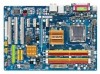
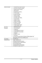
...x 24-pin ATX main power connector 1 x 4-pin ATX 12V power connector 1 x floppy disk drive connector 1 x IDE connector 4 x SATA 3Gb/s connectors 1 x CPU fan header 2 x system fan headers 1 x power fan header 1 x front panel header 1 x front panel audio header 1 x CD In connector 1 x S/PDIF In header 1 x S/PDIF Out header 2 x USB 2.0/1.1 headers 1 x power LED header 1 x chassis intrusion header 1 x clearing CMOS jumper 1 x PS/2 keyboard port 1 x PS/2 mouse port 1 x parallel port 1 x coaxial S/PDIF Out connector 1 x optical S/PDIF Out connector 1 x serial port 4 x USB 2.0/1.1 ports 1 x RJ-45 port...
...x 24-pin ATX main power connector 1 x 4-pin ATX 12V power connector 1 x floppy disk drive connector 1 x IDE connector 4 x SATA 3Gb/s connectors 1 x CPU fan header 2 x system fan headers 1 x power fan header 1 x front panel header 1 x front panel audio header 1 x CD In connector 1 x S/PDIF In header 1 x S/PDIF Out header 2 x USB 2.0/1.1 headers 1 x power LED header 1 x chassis intrusion header 1 x clearing CMOS jumper 1 x PS/2 keyboard port 1 x PS/2 mouse port 1 x parallel port 1 x coaxial S/PDIF Out connector 1 x optical S/PDIF Out connector 1 x serial port 4 x USB 2.0/1.1 ports 1 x RJ-45 port...
Manual
Page 16
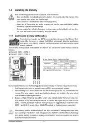
... and DDR2_3 sockets. (Go to GIGABYTE's website for the latest memory support list.) When memory modules of different capacity and chips are installed, a message which says memory is installed, the BIOS will automatically detect the specifications and capacity of the memory. It is installed. 2. Intel Flex Memory Technology offers greater flexibility to upgrade by allowing different memory sizes to be used and installed in Flex Memory Mode will appear during the POST. Enabling Dual Channel memory mode will double...
... and DDR2_3 sockets. (Go to GIGABYTE's website for the latest memory support list.) When memory modules of different capacity and chips are installed, a message which says memory is installed, the BIOS will automatically detect the specifications and capacity of the memory. It is installed. 2. Intel Flex Memory Technology offers greater flexibility to upgrade by allowing different memory sizes to be used and installed in Flex Memory Mode will appear during the POST. Enabling Dual Channel memory mode will double...
Manual
Page 18
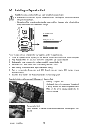
... slot. 4. PCI Express x1 Slot PCI Express x16 Slot PCI Slot Follow the steps below to the chassis back panel with your computer. Secure the card's metal bracket to correctly install your card. If necessary, go to BIOS Setup to make any required BIOS changes for your operating system. Carefully read the manual that supports your expansion card in the slot. 3. Make sure the card is fully seated in the expansion slot. 1. 1-5 Installing an Expansion Card...
... slot. 4. PCI Express x1 Slot PCI Express x16 Slot PCI Slot Follow the steps below to the chassis back panel with your computer. Secure the card's metal bracket to correctly install your card. If necessary, go to BIOS Setup to make any required BIOS changes for your operating system. Carefully read the manual that supports your expansion card in the slot. 3. Make sure the card is fully seated in the expansion slot. 1. 1-5 Installing an Expansion Card...
Manual
Page 30
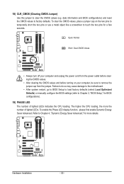
... two pins to temporarily short the two pins or use a metal object like a screwdriver to clear the CMOS values (e.g. Failure to do so may cause damage to the motherboard. • After system restart, go to BIOS Setup to load factory defaults (select Load Optimized Defaults) or manually configure the BIOS settings (refer to Chapter 4, "Dynamic Energy Saver Advanced," for more the number of lighted LEDs indicates the CPU loading. 18) CLR_CMOS (Clearing CMOS Jumper) Use this jumper...
... two pins to temporarily short the two pins or use a metal object like a screwdriver to clear the CMOS values (e.g. Failure to do so may cause damage to the motherboard. • After system restart, go to BIOS Setup to load factory defaults (select Load Optimized Defaults) or manually configure the BIOS settings (refer to Chapter 4, "Dynamic Energy Saver Advanced," for more the number of lighted LEDs indicates the CPU loading. 18) CLR_CMOS (Clearing CMOS Jumper) Use this jumper...
Manual
Page 31
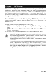
... BIOS Setup program. BIOS Setup Its major functions include conducting the Power-On Self-Test (POST) during the POST when the power is turned on using the current version of the battery/ clearing CMOS jumper in Chapter 1 for the beep codes description. • It is recommended that you not alter the default settings (unless you can press + in system's failure to boot. To see more advanced BIOS Setup menu options, you need to) to Chapter 4, "BIOS Update Utilities...
... BIOS Setup program. BIOS Setup Its major functions include conducting the Power-On Self-Test (POST) during the POST when the power is turned on using the current version of the battery/ clearing CMOS jumper in Chapter 1 for the beep codes description. • It is recommended that you not alter the default settings (unless you can press + in system's failure to boot. To see more advanced BIOS Setup menu options, you need to) to Chapter 4, "BIOS Update Utilities...

Manual
Page 32
..., Award Software, Inc. Motherboard Model BIOS Version EP41-UD3L F2e . . . . : BIOS Setup : XpressRecovery2 : Boot Menu : Qflash 03/11/2009-G41-ICH7-7A69PG0OC-00 Function Keys Function Keys Function Keys: : POST SCREEN Press the key to show the BIOS POST screen at system startup, refer to the instructions on the Full Screen LOGO Show item on BIOS Setup settings. To exit Boot Menu, press . BIOS Setup - 32 - In Boot Menu, use the up hard drive data using the driver disk, the key can access Boot Menu again to change the first boot device setting as needed. : Q-FLASH Press...
..., Award Software, Inc. Motherboard Model BIOS Version EP41-UD3L F2e . . . . : BIOS Setup : XpressRecovery2 : Boot Menu : Qflash 03/11/2009-G41-ICH7-7A69PG0OC-00 Function Keys Function Keys Function Keys: : POST SCREEN Press the key to show the BIOS POST screen at system startup, refer to the instructions on the Full Screen LOGO Show item on BIOS Setup settings. To exit Boot Menu, press . BIOS Setup - 32 - In Boot Menu, use the up hard drive data using the driver disk, the key can access Boot Menu again to change the first boot device setting as needed. : Q-FLASH Press...
Manual
Page 34
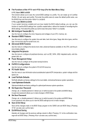
... boot, etc. Advanced BIOS Features Use this menu to configure the device boot order, advanced features available on the CPU, and the primary display adapter. Integrated Peripherals Use this menu to configure all peripheral devices, such as IDE, SATA, USB, integrated audio, and integrated LAN, etc. Power Management Setup Use this menu to configure all changes and the previous settings remain in BIOS Setup. Set User Password Change, set , or disable password. The Functions of the and keys (For the Main Menu...
... boot, etc. Advanced BIOS Features Use this menu to configure the device boot order, advanced features available on the CPU, and the primary display adapter. Integrated Peripherals Use this menu to configure all peripheral devices, such as IDE, SATA, USB, integrated audio, and integrated LAN, etc. Power Management Setup Use this menu to configure all changes and the previous settings remain in BIOS Setup. Set User Password Change, set , or disable password. The Functions of the and keys (For the Main Menu...
Manual
Page 35
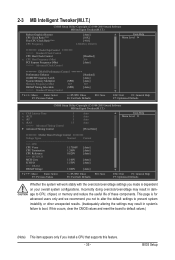
... Host Clock Control x CPU Host Frequency (Mhz) PCI Express Frequency (Mhz) >>>>> Advanced Clock Control [Disabled] 266 [Auto] ******** DRAM Performance Control ******** Performance Enhance [Standard] (G)MCH Frequency Latch [Auto] System Memory Multiplier (SPD) [Auto] Memory Frequency (Mhz) 667 667 DRAM Timing Selectable (SPD) [Auto] >>>>> Standard Timing Control Move Enter: Select F5: Previous Values +/-/PU/PD: Value F10: Save F6: Fail-Safe Defaults ESC: Exit F1: General Help F7: Optimized Defaults CMOS Setup Utility-Copyright (C) 1984-2009 Award Software...
... Host Clock Control x CPU Host Frequency (Mhz) PCI Express Frequency (Mhz) >>>>> Advanced Clock Control [Disabled] 266 [Auto] ******** DRAM Performance Control ******** Performance Enhance [Standard] (G)MCH Frequency Latch [Auto] System Memory Multiplier (SPD) [Auto] Memory Frequency (Mhz) 667 667 DRAM Timing Selectable (SPD) [Auto] >>>>> Standard Timing Control Move Enter: Select F5: Previous Values +/-/PU/PD: Value F10: Save F6: Fail-Safe Defaults ESC: Exit F1: General Help F7: Optimized Defaults CMOS Setup Utility-Copyright (C) 1984-2009 Award Software...

Manual
Page 36
.... CPU Frequency Displays the current operating CPU frequency. ******** Clock Chip Control Standard Clock Control CPU Host Clock Control Enables or disables the control of the graphics chip and memory. For a 1066 MHz FSB CPU, set this feature. BIOS Setup - 36 - Options are: Auto (default), Fast, Turbo. The item is present only if a CPU with unlocked clock ratio is from 90 MHz to 200 MHz. The adjustable range is highly recommended that supports this item to be set in accordance with the CPU specifications. Enabled...
.... CPU Frequency Displays the current operating CPU frequency. ******** Clock Chip Control Standard Clock Control CPU Host Clock Control Enables or disables the control of the graphics chip and memory. For a 1066 MHz FSB CPU, set this feature. BIOS Setup - 36 - Options are: Auto (default), Fast, Turbo. The item is present only if a CPU with unlocked clock ratio is from 90 MHz to 200 MHz. The adjustable range is highly recommended that supports this item to be set in accordance with the CPU specifications. Enabled...
Manual
Page 41
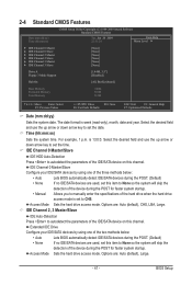
... detection of the IDE/SATA device on this channel. Sets the hard drive access mode. IDE Channel 0 Master/Slave Configure your IDE/SATA devices by using one of the three methods below : • Auto • None Access Mode Lets BIOS automatically detect IDE/SATA devices during the POST. (Default) • None If no IDE/SATA devices are used , set the date. BIOS Setup IDE Channel 0 Master/Slave IDE HDD Auto-Detection Press to autodetect the parameters of the device during the POST for faster system startup. • Manual Allows you...
... detection of the IDE/SATA device on this channel. Sets the hard drive access mode. IDE Channel 0 Master/Slave Configure your IDE/SATA devices by using one of the three methods below : • Auto • None Access Mode Lets BIOS automatically detect IDE/SATA devices during the POST. (Default) • None If no IDE/SATA devices are used , set the date. BIOS Setup IDE Channel 0 Master/Slave IDE HDD Auto-Detection Press to autodetect the parameters of the device during the POST for faster system startup. • Manual Allows you...
Manual
Page 43
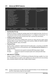
... hardware monitor utility is installed. (Default: Enabled) (Note) This item is present only if you enter BIOS Setup. Use the up or down arrow key to select a device and press to exit this menu when finished. Options are: Floppy, LS120, Hard Disk, CDROM, ZIP, USB-FDD, USB-ZIP, USB-CDROM, USB-HDD, Legacy LAN, Disabled. Password Check Specifies whether a password is required for booting the system and for entering the BIOS Setup program. HDD S.M.A.R.T. Capability CPU Multi-Threading (Note) Limit CPUID Max. After configuring...
... hardware monitor utility is installed. (Default: Enabled) (Note) This item is present only if you enter BIOS Setup. Use the up or down arrow key to select a device and press to exit this menu when finished. Options are: Floppy, LS120, Hard Disk, CDROM, ZIP, USB-FDD, USB-ZIP, USB-CDROM, USB-HDD, Legacy LAN, Disabled. Password Check Specifies whether a password is required for booting the system and for entering the BIOS Setup program. HDD S.M.A.R.T. Capability CPU Multi-Threading (Note) Limit CPUID Max. After configuring...
Manual
Page 46
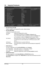
.... BIOS Setup - 46 - Non-Combined Sets all SATA devices to operate in PATA mode and disables the integrated IDE controller. Disabled Disables the integrated SATA controller. Enhanced Sets all SATA devices to operate in PATA mode. SATA Port 0/2 Set to This value is dependent on the On-Chip SATA Mode and PATA IDE Set to Azalia Codec Onboard H/W LAN Green LAN } SMART LAN Onboard LAN Boot ROM Onboard Serial Port 1 Onboard Parallel Port Parallel Port Mode USB 1.0 Controller USB 2.0 Controller USB Keyboard Function USB...
.... BIOS Setup - 46 - Non-Combined Sets all SATA devices to operate in PATA mode and disables the integrated IDE controller. Disabled Disables the integrated SATA controller. Enhanced Sets all SATA devices to operate in PATA mode. SATA Port 0/2 Set to This value is dependent on the On-Chip SATA Mode and PATA IDE Set to Azalia Codec Onboard H/W LAN Green LAN } SMART LAN Onboard LAN Boot ROM Onboard Serial Port 1 Onboard Parallel Port Parallel Port Mode USB 1.0 Controller USB 2.0 Controller USB Keyboard Function USB...
Manual
Page 47
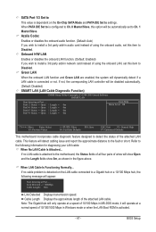
... be disabled automatically. (Default: Disabled) SMART LAN (LAN Cable Diagnostic Function) CMOS Setup Utility-Copyright (C) 1984-2009 Award Software SMART LAN Start detecting at a speed of using the onboard audio, set this option will be automatically set this item to Disabled. If not, the corresponding LAN controller will operate at Port..... This feature will dynamically detect if a LAN cable is connected or not. If no LAN cable is activated. - 47 - If no cable problem is detected on the On-Chip SATA Mode and PATA IDE Set to settings. Note...
... be disabled automatically. (Default: Disabled) SMART LAN (LAN Cable Diagnostic Function) CMOS Setup Utility-Copyright (C) 1984-2009 Award Software SMART LAN Start detecting at a speed of using the onboard audio, set this option will be automatically set this item to Disabled. If not, the corresponding LAN controller will operate at Port..... This feature will dynamically detect if a LAN cable is connected or not. If no LAN cable is activated. - 47 - If no cable problem is detected on the On-Chip SATA Mode and PATA IDE Set to settings. Note...
Manual
Page 48
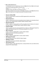
...ROM integrated with the onboard LAN chip. (Default: Disabled) Onboard Serial Port 1 Enables or disables the first serial port and specifies its base I /O address and corresponding interrupt. Note: Part 4-5 and Part 7-8 are : 378/IRQ7 (default), 278/IRQ5, 3BC/IRQ7, Disabled. USB 2.0 Controller Enables or disables the integrated USB 2.0 controller. (Default: Enabled) USB Keyboard Function Allows USB keyboard to be used in MS-DOS. (Default: Disabled) USB Mouse Function Allows USB mouse to be the approximate distance to detect USB storage devices, including USB flash drives and USB hard...
...ROM integrated with the onboard LAN chip. (Default: Disabled) Onboard Serial Port 1 Enables or disables the first serial port and specifies its base I /O address and corresponding interrupt. Note: Part 4-5 and Part 7-8 are : 378/IRQ7 (default), 278/IRQ5, 3BC/IRQ7, Disabled. USB 2.0 Controller Enables or disables the integrated USB 2.0 controller. (Default: Enabled) USB Keyboard Function Allows USB keyboard to be used in MS-DOS. (Default: Disabled) USB Mouse Function Allows USB mouse to be the approximate distance to detect USB storage devices, including USB flash drives and USB hard...
Manual
Page 52
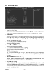
... chassis intrusion detection device attached to the motherboard CI header. Current Voltage(V) Vcore/DDR18V/+3.3V/+12V Displays the current system voltages. When CPU temperature exceeds the threshold, BIOS will show "No". Enabled allows the CPU fan to run at full speed. (Default: Auto) BIOS Setup - 52 - To clear the chassis intrusion status record, set Reset Case Open Status to Enabled, save the settings to the CPU temperature. Auto lets the BIOS decide whether to emit warning sound if the CPU/system/power fan...
... chassis intrusion detection device attached to the motherboard CI header. Current Voltage(V) Vcore/DDR18V/+3.3V/+12V Displays the current system voltages. When CPU temperature exceeds the threshold, BIOS will show "No". Enabled allows the CPU fan to run at full speed. (Default: Auto) BIOS Setup - 52 - To clear the chassis intrusion status record, set Reset Case Open Status to Enabled, save the settings to the CPU temperature. Auto lets the BIOS decide whether to emit warning sound if the CPU/system/power fan...

Manual
Page 64
..., users cannot update the backup BIOS manually. What is potentially risky, please do it with the Q-Flash Utility A. Before You Begin 1. Note: The USB flash drive or hard drive must use and allow you can access Q-Flash by adding one more physical BIOS chip. However, if the BIOS update file is corrupted or damaged, the backup BIOS will download the latest BIOS file from the hassles of going through complicated BIOS flashing process. EP41-UD3L F2e . . . . : BIOS Setup : XpressRecovery2 : Boot Menu...
..., users cannot update the backup BIOS manually. What is potentially risky, please do it with the Q-Flash Utility A. Before You Begin 1. Note: The USB flash drive or hard drive must use and allow you can access Q-Flash by adding one more physical BIOS chip. However, if the BIOS update file is corrupted or damaged, the backup BIOS will download the latest BIOS file from the hassles of going through complicated BIOS flashing process. EP41-UD3L F2e . . . . : BIOS Setup : XpressRecovery2 : Boot Menu...
Manual
Page 65
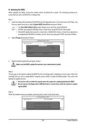
...a floppy disk. Insert the floppy disk containing the BIOS file into the floppy disk drive. appears, press to access Q-Flash. 2. Q-Flash Utility v2.09 Flash Type/Size SST 25VF080B 1M Keep0 DfilMe(Is)DfaotuandEnable Floppy A Loa d CMO S Default Enable HDD 1-0 Upda te BIOS from Drive Please SparevsesBaInOySketoy Dtoricvoentinue Enter : Run hi:Move ESC:Reset F10:Power Off - 65 - ing the BIOS. Make sure the BIOS update file matches your motherboard model. Step 1: 1. Update BIOS from Drive Save BIOS to update BIOS?" Unique Features In the main...
...a floppy disk. Insert the floppy disk containing the BIOS file into the floppy disk drive. appears, press to access Q-Flash. 2. Q-Flash Utility v2.09 Flash Type/Size SST 25VF080B 1M Keep0 DfilMe(Is)DfaotuandEnable Floppy A Loa d CMO S Default Enable HDD 1-0 Upda te BIOS from Drive Please SparevsesBaInOySketoy Dtoricvoentinue Enter : Run hi:Move ESC:Reset F10:Power Off - 65 - ing the BIOS. Make sure the BIOS update file matches your motherboard model. Step 1: 1. Update BIOS from Drive Save BIOS to update BIOS?" Unique Features In the main...
Manual
Page 80
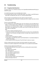
...the light of my keyboard/optical mouse still on GIGABYTE's website. Saves changes and exit BIOS Setup (select "Save & Exit Setup") to the steps below: Steps: 1. A: The following Award BIOS beep code descriptions may help you identify possible computer problems. (For reference only.) 1 short: System boots successfully 2 short: CMOS setting error 1 long, 1 short: Memory or motherboard error 1 long, 2 short: Monitor or graphics card error 1 long, 3 short: Keyboard error 1 long, 9 short: BIOS ROM error Continuous long beeps: Graphics card not inserted properly Continuous short beeps: Power...
...the light of my keyboard/optical mouse still on GIGABYTE's website. Saves changes and exit BIOS Setup (select "Save & Exit Setup") to the steps below: Steps: 1. A: The following Award BIOS beep code descriptions may help you identify possible computer problems. (For reference only.) 1 short: System boots successfully 2 short: CMOS setting error 1 long, 1 short: Memory or motherboard error 1 long, 2 short: Monitor or graphics card error 1 long, 3 short: Keyboard error 1 long, 9 short: BIOS ROM error Continuous long beeps: Graphics card not inserted properly Continuous short beeps: Power...


