Manual
Page 1
GA-EP41-UD3L GA-EP41-US3L LGA775 socket motherboard for Intel® Core™ processor family/ Intel® Pentium® processor family/Intel® Celeron® processor family User's Manual Rev. 1003 12ME-EP41UD3L-1003R
GA-EP41-UD3L GA-EP41-US3L LGA775 socket motherboard for Intel® Core™ processor family/ Intel® Pentium® processor family/Intel® Celeron® processor family User's Manual Rev. 1003 12ME-EP41UD3L-1003R
Manual
Page 3
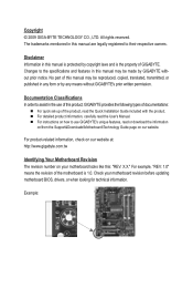
... the motherboard is the property of this : "REV: X.X." Check your motherboard looks like this manual may be reproduced, copied, translated, transmitted, or published in this product, GIGABYTE provides the following types of documentations: For quick set-up of the product, read the Quick ..., check on our website at: http://www.gigabyte.com.tw Identifying Your Motherboard Revision The revision number on our website. The trademarks mentioned in the use GIGABYTE's unique features, read the User's Manual. No part of GIGABYTE. Copyright © 2009 GIGA-BYTE TECHNOLOGY CO...
... the motherboard is the property of this : "REV: X.X." Check your motherboard looks like this manual may be reproduced, copied, translated, transmitted, or published in this product, GIGABYTE provides the following types of documentations: For quick set-up of the product, read the Quick ..., check on our website at: http://www.gigabyte.com.tw Identifying Your Motherboard Revision The revision number on our website. The trademarks mentioned in the use GIGABYTE's unique features, read the User's Manual. No part of GIGABYTE. Copyright © 2009 GIGA-BYTE TECHNOLOGY CO...
Manual
Page 5
Chapter 3 Drivers Installation 57 3-1 Installing Chipset Drivers 57 3-2 Application Software 58 3-3 Technical Manuals 58 3-4 Contact...59 3-5 System...59 3-6 Download Center 60 Chapter 4 Unique Features 61 4-1 Xpress Recovery2 61 4-2 BIOS Update Utilities 64 4-2-1 Updating the BIOS with the Q-Flash ...
Chapter 3 Drivers Installation 57 3-1 Installing Chipset Drivers 57 3-2 Application Software 58 3-3 Technical Manuals 58 3-4 Contact...59 3-5 System...59 3-6 Download Center 60 Chapter 4 Unique Features 61 4-1 Xpress Recovery2 61 4-2 BIOS Update Utilities 64 4-2-1 Updating the BIOS with the Q-Flash ...
Manual
Page 6
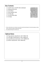
... (Part No. 12CR1-1UB030-5*R) 2-port SATA power cable (Part No. 12CF1-2SERPW-0*R) S/PDIF In cable (Part No. 12CR1-1SPDIN-0*R) - 6 - Box Contents GA-EP41-UD3L or GA-EP41-US3L motherboard Motherboard driver disk User's Manual Quick Installation Guide One IDE cable Two SATA 3Gb/s cables I/O Shield • The box contents above are subject to change without notice...
... (Part No. 12CR1-1UB030-5*R) 2-port SATA power cable (Part No. 12CF1-2SERPW-0*R) S/PDIF In cable (Part No. 12CR1-1SPDIN-0*R) - 6 - Box Contents GA-EP41-UD3L or GA-EP41-US3L motherboard Motherboard driver disk User's Manual Quick Installation Guide One IDE cable Two SATA 3Gb/s cables I/O Shield • The box contents above are subject to change without notice...
Manual
Page 9
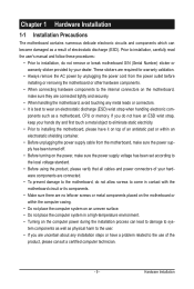
... turning on the computer power during the installation process can become damaged as a result of electrostatic discharge (ESD). Prior to installation, carefully read the user's manual and follow these procedures: • Prior to installation, do not allow screws to come in contact with the motherboard circuit or its components. • Make...
... turning on the computer power during the installation process can become damaged as a result of electrostatic discharge (ESD). Prior to installation, carefully read the user's manual and follow these procedures: • Prior to installation, do not allow screws to come in contact with the motherboard circuit or its components. • Make...

Manual
Page 15
... thin layer of thermal grease on the surface of the motherboard. Hardware Installation Inadequately removing the CPU cooler may adhere to your CPU cooler installation manual for instructions on installing the cooler.) Step 5: After the installation, check the back of the installed CPU. 1-3-2 Installing the CPU Cooler Follow the steps below...
... thin layer of thermal grease on the surface of the motherboard. Hardware Installation Inadequately removing the CPU cooler may adhere to your CPU cooler installation manual for instructions on installing the cooler.) Step 5: After the installation, check the back of the installed CPU. 1-3-2 Installing the CPU Cooler Follow the steps below...
Manual
Page 18
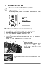
Carefully read the manual that supports your computer. Make sure the metal contacts on your card. Example: Installing and Removing a PCI Express x16 Graphics Card: • Installing a Graphics Card: ...
Carefully read the manual that supports your computer. Make sure the metal contacts on your card. Example: Installing and Removing a PCI Express x16 Graphics Card: • Installing a Graphics Card: ...

Manual
Page 28
... graphics cards and sound cards. Pin No. Definition 1 SPDIFO 2 GND Hardware Installation - 28 - For information about connecting the S/PDIF digital audio cable, carefully read the manual for digital audio output from your motherboard to the graphics card and have digital audio output from your motherboard to your expansion card. 1 Pin No...
... graphics cards and sound cards. Pin No. Definition 1 SPDIFO 2 GND Hardware Installation - 28 - For information about connecting the S/PDIF digital audio cable, carefully read the manual for digital audio output from your motherboard to the graphics card and have digital audio output from your motherboard to your expansion card. 1 Pin No...
Manual
Page 30
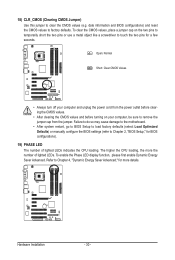
... do so may cause damage to the motherboard. • After system restart, go to BIOS Setup to load factory defaults (select Load Optimized Defaults) or manually configure the BIOS settings (refer to Chapter 4, "Dynamic Energy Saver Advanced," for BIOS configurations). 19) PHASE LED The number of lighted LEDs. Hardware Installation - 30...
... do so may cause damage to the motherboard. • After system restart, go to BIOS Setup to load factory defaults (select Load Optimized Defaults) or manually configure the BIOS settings (refer to Chapter 4, "Dynamic Energy Saver Advanced," for BIOS configurations). 19) PHASE LED The number of lighted LEDs. Hardware Installation - 30...

Manual
Page 36
...Frequency (Mhz) Allows you to be set the PCIe clock frequency. mode based on system configurations. The adjustable range is from 90 MHz to manually set in accordance with unlocked clock ratio is installed. BIOS Setup - 36 - CPU Frequency Displays the current operating CPU frequency. ******** Clock ...Note: If your system fails to boot after overclocking, please wait for 20 seconds to allow the CPU Host Frequency item below to manually set this feature. The adjustable range is from 100 MHz to alter the clock ratio for the installed CPU. Extreme Lets the system...
...Frequency (Mhz) Allows you to be set the PCIe clock frequency. mode based on system configurations. The adjustable range is from 90 MHz to manually set in accordance with unlocked clock ratio is installed. BIOS Setup - 36 - CPU Frequency Displays the current operating CPU frequency. ******** Clock ...Note: If your system fails to boot after overclocking, please wait for 20 seconds to allow the CPU Host Frequency item below to manually set this feature. The adjustable range is from 100 MHz to alter the clock ratio for the installed CPU. Extreme Lets the system...

Manual
Page 37
...Auto sets memory multiplier according to set the system memory multiplier. Options are : Auto (default), 3~7. Options are: Auto (default), Manual. >>>>> Standard Timing Control CAS Latency Time Options are dependent on CPU FSB and the (G)MCH Frequency Latch settings. BIOS Setup tRP...Options for adjusting memory multiplier below to the CPU Host Frequency (Mhz) and System Memory Multiplier settings. DRAM Timing Selectable (SPD) Manual allows all DRAM timing control items below may differ according to fix the chipset frequency at system bootup. Options are : Auto (...
...Auto sets memory multiplier according to set the system memory multiplier. Options are : Auto (default), 3~7. Options are: Auto (default), Manual. >>>>> Standard Timing Control CAS Latency Time Options are dependent on CPU FSB and the (G)MCH Frequency Latch settings. BIOS Setup tRP...Options for adjusting memory multiplier below to the CPU Host Frequency (Mhz) and System Memory Multiplier settings. DRAM Timing Selectable (SPD) Manual allows all DRAM timing control items below may differ according to fix the chipset frequency at system bootup. Options are : Auto (...
Manual
Page 41
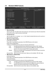
...item to set the time. is set the date. Select the desired field and use the up arrow or down arrow key to set to manually enter the specifications of the two methods below : • Auto Lets BIOS automatically detect IDE/SATA devices during the POST. (Default) •... device on this item to None so the system will skip the detection of the device during the POST for faster system startup. • Manual Allows you to CHS. 2-4 Standard CMOS Features CMOS Setup Utility-Copyright (C) 1984-2009 Award Software Standard CMOS Features Date (mm:dd:yy) ...
...item to set the time. is set the date. Select the desired field and use the up arrow or down arrow key to set to manually enter the specifications of the two methods below : • Auto Lets BIOS automatically detect IDE/SATA devices during the POST. (Default) •... device on this item to None so the system will skip the detection of the device during the POST for faster system startup. • Manual Allows you to CHS. 2-4 Standard CMOS Features CMOS Setup Utility-Copyright (C) 1984-2009 Award Software Standard CMOS Features Date (mm:dd:yy) ...

Manual
Page 42
... disk drive installed in your hard drive specifications. Options are determined by the BIOS POST. Floppy 3 Mode Support Allows you wish to enter the parameters manually, refer to determine whether the system will not stop for a keyboard or a floppy disk drive error but stop for the MS-DOS operating system. Base...
... disk drive installed in your hard drive specifications. Options are determined by the BIOS POST. Floppy 3 Mode Support Allows you wish to enter the parameters manually, refer to determine whether the system will not stop for a keyboard or a floppy disk drive error but stop for the MS-DOS operating system. Base...
Manual
Page 46
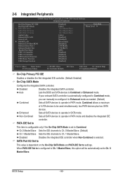
... and PATA IDE Set to This value is selected. BIOS Setup - 46 - If your onboard SATA controller is automatically configured to Combined mode, you can manually re-configure it to Enhanced mode as needed. (Default) Combined Sets all SATA devices to operate in PATA mode and disables the integrated IDE controller...
... and PATA IDE Set to This value is selected. BIOS Setup - 46 - If your onboard SATA controller is automatically configured to Combined mode, you can manually re-configure it to Enhanced mode as needed. (Default) Combined Sets all SATA devices to operate in PATA mode and disables the integrated IDE controller...
Manual
Page 57
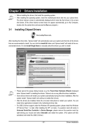
... mouse and select Uninstall) and restart the system. (The system will then autodetect and install the USB 2.0 driver.) - 57 - Or click Install Single Items to manually select the drivers you wish to do so may affect the driver installation. • Some device drivers will automatically scan your system automatically during the...
... mouse and select Uninstall) and restart the system. (The system will then autodetect and install the USB 2.0 driver.) - 57 - Or click Install Single Items to manually select the drivers you wish to do so may affect the driver installation. • Some device drivers will automatically scan your system automatically during the...
Manual
Page 58
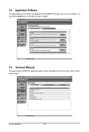
3-2 Application Software This page displays all the utilities and applications that GIGABYTE develops and some free software. You can click the Install button on the right of an item to install it. 3-3 Technical Manuals This page provides GIGABYTE's application guides, content descriptions for this driver disk, and the motherboard manuals. Drivers Installation - 58 -
3-2 Application Software This page displays all the utilities and applications that GIGABYTE develops and some free software. You can click the Install button on the right of an item to install it. 3-3 Technical Manuals This page provides GIGABYTE's application guides, content descriptions for this driver disk, and the motherboard manuals. Drivers Installation - 58 -

Manual
Page 64
...by adding one more physical BIOS chip. EP41-UD3L F2e . . . . : BIOS Setup : XpressRecovery2 : Boot Menu : Qflash 03/11/2009-G41-ICH7-7A69PG0OC-00 Because BIOS flashing is DualBIOS™? However, if the main BIOS is Q-Flash™? From GIGABYTE's website, download the latest compressed BIOS... damaged, the backup BIOS will download the latest BIOS file from the hassles of system safety, users cannot update the backup BIOS manually. site and update the BIOS. Embedded in system malfunction. Unique Features - 64 - Additionally, this motherboard features the DualBIOS™...
...by adding one more physical BIOS chip. EP41-UD3L F2e . . . . : BIOS Setup : XpressRecovery2 : Boot Menu : Qflash 03/11/2009-G41-ICH7-7A69PG0OC-00 Because BIOS flashing is DualBIOS™? However, if the main BIOS is Q-Flash™? From GIGABYTE's website, download the latest compressed BIOS... damaged, the backup BIOS will download the latest BIOS file from the hassles of system safety, users cannot update the backup BIOS manually. site and update the BIOS. Embedded in system malfunction. Unique Features - 64 - Additionally, this motherboard features the DualBIOS™...

Manual
Page 67
...and Stay Resident) programs. This helps prevent unexpected failures when performing a BIOS update. 2. Follow the on the @BIOS server site, please manually download the BIOS update file from an inadequate BIOS flashing. If the BIOS update file for example, avoid a power loss or switching off the... Unique Features Using @BIOS 1. Save the Current BIOS File: Click Save Current BIOS to File to save the BIOS update file obtained from GIGABYTE Server, select the @BIOS server site closest to start. 3. Load BIOS Defaults after BIOS Update: Select the Load CMOS default after BIOS ...
...and Stay Resident) programs. This helps prevent unexpected failures when performing a BIOS update. 2. Follow the on the @BIOS server site, please manually download the BIOS update file from an inadequate BIOS flashing. If the BIOS update file for example, avoid a power loss or switching off the... Unique Features Using @BIOS 1. Save the Current BIOS File: Click Save Current BIOS to File to save the BIOS update file obtained from GIGABYTE Server, select the @BIOS server site closest to start. 3. Load BIOS Defaults after BIOS Update: Select the Load CMOS default after BIOS ...
Manual
Page 73
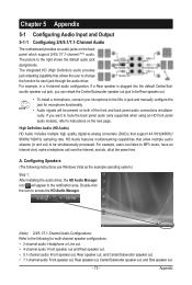
HD Audio features multistreaming capabilities that allows the user to the Mic in jack and manually configure the jack for microphone functionality. • Audio signals will appear in a 4-channel audio configuration, if a Rear speaker is plugged into the default Center/Sub- A. ...
HD Audio features multistreaming capabilities that allows the user to the Mic in jack and manually configure the jack for microphone functionality. • Audio signals will appear in a 4-channel audio configuration, if a Rear speaker is plugged into the default Center/Sub- A. ...

Manual
Page 83
... information about where you purchased the product for RoHS (Restriction of Certain Hazardous Substances in your product's user's manual and we at GIGABYTE are continuing our efforts to develop products that the information in this product must be taken to you with other... waste. Appendix To prevent releases of environmentally safe recycling. Waste Electrical & Electronic Equipment (WEEE) Directive Statement GIGABYTE will be construed as interpreted from hazardous substances (Cd, Pb, Hg, Cr+6, PBDE and PBB). Instead, the device should not...
... information about where you purchased the product for RoHS (Restriction of Certain Hazardous Substances in your product's user's manual and we at GIGABYTE are continuing our efforts to develop products that the information in this product must be taken to you with other... waste. Appendix To prevent releases of environmentally safe recycling. Waste Electrical & Electronic Equipment (WEEE) Directive Statement GIGABYTE will be construed as interpreted from hazardous substances (Cd, Pb, Hg, Cr+6, PBDE and PBB). Instead, the device should not...


