

Manual/User Guide
Page 2
.... All Right Reserved, Copyright © FUJITSU LIMITED 2002 C141-E166 FUJITSU makes every effort to ensure the accuracy of all information in this manual, FUJITSU assumes no liability with the descriptions or instructions contained herein; While FUJITSU has sought to prevent users and bystanders from..., medical devices for life support, or weapons firing controls) where particularly high reliability requirements exist, where the pertinent levels of Fujitsu Limited. Use this manual. INCORRECT USE OF THE PRODUCT MAY RESULT IN INJURY OR DAMAGE TO USERS, BYSTANDERS OR PROPERTY. including ...
.... All Right Reserved, Copyright © FUJITSU LIMITED 2002 C141-E166 FUJITSU makes every effort to ensure the accuracy of all information in this manual, FUJITSU assumes no liability with the descriptions or instructions contained herein; While FUJITSU has sought to prevent users and bystanders from..., medical devices for life support, or weapons firing controls) where particularly high reliability requirements exist, where the pertinent levels of Fujitsu Limited. Use this manual. INCORRECT USE OF THE PRODUCT MAY RESULT IN INJURY OR DAMAGE TO USERS, BYSTANDERS OR PROPERTY. including ...
Manual/User Guide
Page 15
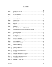
FIGURES Figure 1.1 Figure 1.2 Figure 1.3 Figure 1.4 page NC model drives outer view 1-6 NP model drives outer view 1-6 Disk/head configuration...1-7 System configuration ...1-9 Figure 3.1 Figure 3.2 Figure 3.3 Figure 3.4 Figure 3.5 Figure 3.6 Figure 3.7 ... Figure 4.16 Figure 4.17 Figure 4.18 Figure 4.19 NC external dimensions...4-2 NP external dimensions ...4-3 IDD orientations ...4-4 Mounting frame structure ...4-5 Limitation of side-mounting 4-5 Surface temperature measurement points 4-6 Service clearance area ...4-7 Current waveform (+12 VDC 4-8 Power on/off sequence (1) ...4-9 Power...
FIGURES Figure 1.1 Figure 1.2 Figure 1.3 Figure 1.4 page NC model drives outer view 1-6 NP model drives outer view 1-6 Disk/head configuration...1-7 System configuration ...1-9 Figure 3.1 Figure 3.2 Figure 3.3 Figure 3.4 Figure 3.5 Figure 3.6 Figure 3.7 ... Figure 4.16 Figure 4.17 Figure 4.18 Figure 4.19 NC external dimensions...4-2 NP external dimensions ...4-3 IDD orientations ...4-4 Mounting frame structure ...4-5 Limitation of side-mounting 4-5 Surface temperature measurement points 4-6 Service clearance area ...4-7 Current waveform (+12 VDC 4-8 Power on/off sequence (1) ...4-9 Power...
Manual/User Guide
Page 21
... the subsequent command requests the prefetched data blocks. The maximum data transfer rate in synchronous mode may be limited by specifying block number in a command can be limited by the reordering function. The high speed sequential data access can be achieved by transferring the data from ...the data buffer without concerning the physical structure of the track or cylinder boundaries. To ensure it, you turn off the drive's power. Data is...
... the subsequent command requests the prefetched data blocks. The maximum data transfer rate in synchronous mode may be limited by specifying block number in a command can be limited by the reordering function. The high speed sequential data access can be achieved by transferring the data from ...the data buffer without concerning the physical structure of the track or cylinder boundaries. To ensure it, you turn off the drive's power. Data is...

Manual/User Guide
Page 57
C141-E166 4-5 Do not use these holes Holes for mounting screw. 1 Use four holes (No.1-4) to mount. Figure 4.5 Limitation of side-mounting (3) Limitation of using the 4 screw holes at the both ends on the both ends. (Total 6 screws for 6 holes enclosed) 4 Holes for mounting screw.... 3 2 Do not use the center hole by itself. 5.0 or less 5.0 or less Figure 4.4 Mounting frame structure (2) Limitation of side-mounting Mount the IDD using the center hole, it must be used in combination with 2 holes on both sides as shown in Figure...
C141-E166 4-5 Do not use these holes Holes for mounting screw. 1 Use four holes (No.1-4) to mount. Figure 4.5 Limitation of side-mounting (3) Limitation of using the 4 screw holes at the both ends on the both ends. (Total 6 screws for 6 holes enclosed) 4 Holes for mounting screw.... 3 2 Do not use the center hole by itself. 5.0 or less 5.0 or less Figure 4.4 Mounting frame structure (2) Limitation of side-mounting Mount the IDD using the center hole, it must be used in combination with 2 holes on both sides as shown in Figure...

Manual/User Guide
Page 93
...) at seek error Default value 15 C141-E166 5-19 5. The saved value of ECC error correction • Retry count at write operation • Recovery time limit Default value 1 (enabled) 1 (enabled) 1 (enabled) 1 (enabled) 0 (disabled) 0 (Correction is enabled.) 63 c.
...) at seek error Default value 15 C141-E166 5-19 5. The saved value of ECC error correction • Retry count at write operation • Recovery time limit Default value 1 (enabled) 1 (enabled) 1 (enabled) 1 (enabled) 0 (disabled) 0 (Correction is enabled.) 63 c.
Manual/User Guide
Page 124
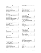
... space 3-4 L large capacity 1-5 leak magnetic flux 4-7 limitation of bottom-mounting 4-5 limitation of side-mounting 4-5 logical data block addressing 3-9 low ...noise and low vibration 1-5 low power consumption 1-5 M maintenance level 6-8 maintenance requirement 6-6 mean time between failure (MTBF 2-5 mean time to repair (MTTR 2-6 microcode downloading 1-5 MODE SELECT/MODE SELECT EXTENDED command............5-16 mode setting 5-9 motor start mode 5-8 motor start mode setting 5-8 mounting 4-4 mounting drive...
... space 3-4 L large capacity 1-5 leak magnetic flux 4-7 limitation of bottom-mounting 4-5 limitation of side-mounting 4-5 logical data block addressing 3-9 low ...noise and low vibration 1-5 low power consumption 1-5 M maintenance level 6-8 maintenance requirement 6-6 mean time between failure (MTBF 2-5 mean time to repair (MTTR 2-6 microcode downloading 1-5 MODE SELECT/MODE SELECT EXTENDED command............5-16 mode setting 5-9 motor start mode 5-8 motor start mode setting 5-8 mounting 4-4 mounting drive...

Manual/User Guide
Page 127
...Place, Island East, Hong Kong TEL: 852-2827-5780 FAX: 852-2827-4724 FUJITSU KOREA LTD. Coryo Finance Center Bldg, 23-6, YoulDo-Dong, Young DungPo-Gu, Seoul, Republic of the following addresses: FUJITSU LIMITED Storage Products Group 4-1-1 Kamikodanaka, Nakahara-ku, Kawasaki, 211-8588, Japan TEL: ..., Ontario L4W 4X5, CANADA TEL: 1-905-602-5454 FAX: 1-905-602-5457 FUJITSU EUROPE LIMITED Hayes Park Central, Hayes End Road,, Hayes, UB4 8FE, U.K. TEL: 1-408-432-6333 FAX: 1-408-894-1709 FUJITSU CANADA INC. 2800 Matheson Blvd. LTD 20 Science Park Road #03-01, TELETECH...
...Place, Island East, Hong Kong TEL: 852-2827-5780 FAX: 852-2827-4724 FUJITSU KOREA LTD. Coryo Finance Center Bldg, 23-6, YoulDo-Dong, Young DungPo-Gu, Seoul, Republic of the following addresses: FUJITSU LIMITED Storage Products Group 4-1-1 Kamikodanaka, Nakahara-ku, Kawasaki, 211-8588, Japan TEL: ..., Ontario L4W 4X5, CANADA TEL: 1-905-602-5454 FAX: 1-905-602-5457 FUJITSU EUROPE LIMITED Hayes Park Central, Hayes End Road,, Hayes, UB4 8FE, U.K. TEL: 1-408-432-6333 FAX: 1-408-894-1709 FUJITSU CANADA INC. 2800 Matheson Blvd. LTD 20 Science Park Road #03-01, TELETECH...

Manual/User Guide
Page 129
... Thank you use this sheet to one of this publication. Learning Installing Reference Maintaining Sales Operating Is the material presented effectively? Please be entered here. FUJITSU LIMITED Reader Comment Form Publication No. Rev. Fully covered Well Illustrated What is your comments and suggestions for your overall rating of the addresses in a previous...
... Thank you use this sheet to one of this publication. Learning Installing Reference Maintaining Sales Operating Is the material presented effectively? Please be entered here. FUJITSU LIMITED Reader Comment Form Publication No. Rev. Fully covered Well Illustrated What is your comments and suggestions for your overall rating of the addresses in a previous...