
Manual/User Guide
Page 5
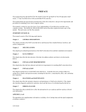
...physical and electrical requirements for setting device number and operation modes, mounting the disk drive, connecting the cables, and confirming drive operation. Chapter 3 DATA FORMAT This chapter describes the data structure of the above disk drive, and gives the requirements and ...disk, the address method, and what to do about media defects. This manual is written for error analysis and how analyze collected error information. PREFACE This manual describes the MAP3147NC/NP, MAP3735NC/NP and MAP3367NC/NP (hereafter, MAP series), 3.5 type fixed disk drives with an embedded SCSI...
...physical and electrical requirements for setting device number and operation modes, mounting the disk drive, connecting the cables, and confirming drive operation. Chapter 3 DATA FORMAT This chapter describes the data structure of the above disk drive, and gives the requirements and ...disk, the address method, and what to do about media defects. This manual is written for error analysis and how analyze collected error information. PREFACE This manual describes the MAP3147NC/NP, MAP3735NC/NP and MAP3367NC/NP (hereafter, MAP series), 3.5 type fixed disk drives with an embedded SCSI...
Manual/User Guide
Page 8
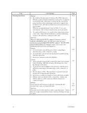
... do not touch the mechanical assembly during servicing or repair. Caution 1. Do not use solvents to clean a disk drive assembly. 5. Check that the SCSI device with the CHECK CONDITION status, the INIT must collect the error information using the REQUEST SENSE command. Data loss ...the SCSI connectors. Fujitsu 6-7 does not assume responsibility if data is the last device connected to the device. 2. When the recommended parts listed in Table 4.2 are marked with a colored line. Connect the ribbon cable to a cable connector with a wrist strap connected to the disk drive, ...
... do not touch the mechanical assembly during servicing or repair. Caution 1. Do not use solvents to clean a disk drive assembly. 5. Check that the SCSI device with the CHECK CONDITION status, the INIT must collect the error information using the REQUEST SENSE command. Data loss ...the SCSI connectors. Fujitsu 6-7 does not assume responsibility if data is the last device connected to the device. 2. When the recommended parts listed in Table 4.2 are marked with a colored line. Connect the ribbon cable to a cable connector with a wrist strap connected to the disk drive, ...
Manual/User Guide
Page 20
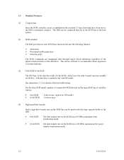
.... For the ultra SCSI model, number of connectable SCSI devices on the same SCSI bus is varied as follows. • 8-bit SCSI: 8 drives max. (option for NP model) • 16-bit SCSI: 16 drives max. (4) High speed data transfer Such a high data transfer rate on the SCSI bus is 320 MB...large capacity buffer in the standard 3.5 type fixed disk drive form factor, the IDD is extremely compact. 1.1 Standard Features (1) Compactness Since the SCSI controller circuit is embedded in the IDD. • 8-bit SCSI: The data transfer rate on the SCSI bus is 40 MB/s maximum at the synchronous ...
.... For the ultra SCSI model, number of connectable SCSI devices on the same SCSI bus is varied as follows. • 8-bit SCSI: 8 drives max. (option for NP model) • 16-bit SCSI: 16 drives max. (4) High speed data transfer Such a high data transfer rate on the SCSI bus is 320 MB...large capacity buffer in the standard 3.5 type fixed disk drive form factor, the IDD is extremely compact. 1.1 Standard Features (1) Compactness Since the SCSI controller circuit is embedded in the IDD. • 8-bit SCSI: The data transfer rate on the SCSI bus is 40 MB/s maximum at the synchronous ...
Manual/User Guide
Page 21
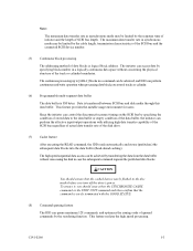
... SCSI device number. (5) Continuous block processing The addressing method of SCSI bus length. The high speed sequential data access can perform the effective input/output operations with the GOOD STATUS. (8) Command queuing feature The IDD can queue maximum 128 commands, and optimizes the issuing order of the disk drive....limited by the response time of initiator and the length of data blocks is transferred between SCSI bus and disk media through this data buffer. To ensure it, you turn off the drive's power. The maximum data transfer rate in a command can be limited by the reordering...
... SCSI device number. (5) Continuous block processing The addressing method of SCSI bus length. The high speed sequential data access can perform the effective input/output operations with the GOOD STATUS. (8) Command queuing feature The IDD can queue maximum 128 commands, and optimizes the issuing order of the disk drive....limited by the response time of initiator and the length of data blocks is transferred between SCSI bus and disk media through this data buffer. To ensure it, you turn off the drive's power. The maximum data transfer rate in a command can be limited by the reordering...
Manual/User Guide
Page 28
... (LUN: logical unit number) is possible on multi-SCSI devices. (2) Addressing of peripheral device Each SCSI device on which multiple host computers that operates as target is a single logical unit, the selectable number of disk drive is addressed in Figure 1.4). For input/output operation, a peripheral device attached to the SCSI bus that operate as an initiator or a target can...
... (LUN: logical unit number) is possible on multi-SCSI devices. (2) Addressing of peripheral device Each SCSI device on which multiple host computers that operates as target is a single logical unit, the selectable number of disk drive is addressed in Figure 1.4). For input/output operation, a peripheral device attached to the SCSI bus that operate as an initiator or a target can...
Manual/User Guide
Page 30
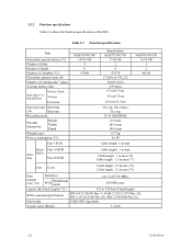
...device (*1) Number of disks Number of heads Number of cylinders (*2) Formatted capacity/track (B) Number of the IDD. Fast 10 SCSI Inter- Ended face Fast 20 SCSI Cable length: 3 m max Cable length: 3 m max (*6) Cable length: 1.5 m max (*7) LVD U160 Cable length: 25 m max (*8) Cable length: 12 m max (*9) Data transfer rate (*10) Disk drive SCSI... 73.50 GB 2 4 47,978 272,896 to 479,232 10,025±0.2% 2.99 msec 0.3 ms/0.5 ms 4.5 ms/5.0 ms 10.0 ms/11.0 ms 30 s typ. (60 s max.) 30 s typ. 32/34 MEEPRML 25.4 mm 101.6 mm 146.0 mm 0.75 kg 9.6 W Cable length: 6 m max MAP3367NC/NP 36.74 GB 1 2 ...
...device (*1) Number of disks Number of heads Number of cylinders (*2) Formatted capacity/track (B) Number of the IDD. Fast 10 SCSI Inter- Ended face Fast 20 SCSI Cable length: 3 m max Cable length: 3 m max (*6) Cable length: 1.5 m max (*7) LVD U160 Cable length: 25 m max (*8) Cable length: 12 m max (*9) Data transfer rate (*10) Disk drive SCSI... 73.50 GB 2 4 47,978 272,896 to 479,232 10,025±0.2% 2.99 msec 0.3 ms/0.5 ms 4.5 ms/5.0 ms 10.0 ms/11.0 ms 30 s typ. (60 s max.) 30 s typ. 32/34 MEEPRML 25.4 mm 101.6 mm 146.0 mm 0.75 kg 9.6 W Cable length: 6 m max MAP3367NC/NP 36.74 GB 1 2 ...
Manual/User Guide
Page 31
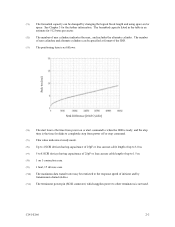
See Chapter 3 for disks to completely stop from power off or stop command. (*5) This value indicates at ...time is the time for the further information. (*1) The formatted capacity can use cable length of up to 8 SCSI devices having capacitance of 25pF or less can use cable length of user cylinders indicates the max., and includes the alternate...used. The number of user cylinders and alternate cylinders can be specified at ready mode. (*6) Up to 4 SCSI devices having capacitance of 25pF or less can be restricted to the response speed of initiator and by changing the logical...
See Chapter 3 for disks to completely stop from power off or stop command. (*5) This value indicates at ...time is the time for the further information. (*1) The formatted capacity can use cable length of up to 8 SCSI devices having capacitance of 25pF or less can use cable length of user cylinders indicates the max., and includes the alternate...used. The number of user cylinders and alternate cylinders can be specified at ready mode. (*6) Up to 4 SCSI devices having capacitance of 25pF or less can be restricted to the response speed of initiator and by changing the logical...
Manual/User Guide
Page 90
...motor start mode and UNIT ATTENTION report mode. 5.6.3 Formatting Since the disk drive is installed in the format parameter (page code = 3) and drive parameter (page code = 4). 5-16 C141-E166 The parameters are ...connected correctly. • The terminating resistor is mounted on both ends of data blocks" field. (2) Checking at installation. c) Check the setting of SCSI Logical Interface Specifications for the SCSI cable connection: • All connectors including other SCSI devices...
...motor start mode and UNIT ATTENTION report mode. 5.6.3 Formatting Since the disk drive is installed in the format parameter (page code = 3) and drive parameter (page code = 4). 5-16 C141-E166 The parameters are ...connected correctly. • The terminating resistor is mounted on both ends of data blocks" field. (2) Checking at installation. c) Check the setting of SCSI Logical Interface Specifications for the SCSI cable connection: • All connectors including other SCSI devices...
Manual/User Guide
Page 113
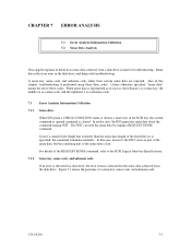
...the sense data, but the remaining part of the REQUEST SENSE command, refer to the SCSI Logical Interface Specifications. 7.1.2 Sense key, sense code, and subsense code If an error is detected in a disk drive, the error status is performed using these three codes. Sense data reflects an error ...data by issuing a REQUEST SENSE command. For details of the sense data is cleared. C141-E166 7-1 Figure 7.1 shows the positions of the tested device is shorter than the sense data length of a sense key, sense code, and subsense code. Even if a transfer byte length that is specified...
...the sense data, but the remaining part of the REQUEST SENSE command, refer to the SCSI Logical Interface Specifications. 7.1.2 Sense key, sense code, and subsense code If an error is detected in a disk drive, the error status is performed using these three codes. Sense data reflects an error ...data by issuing a REQUEST SENSE command. For details of the sense data is cleared. C141-E166 7-1 Figure 7.1 shows the positions of the tested device is shorter than the sense data length of a sense key, sense code, and subsense code. Even if a transfer byte length that is specified...
Manual/User Guide
Page 123
... 4-C4-xx 7-4 5-2x-xx 7-4 5-3D-00 7-4 5-90-00 7-4 68 pin type LVD 16-bit SCSI B-2 8-bit SCSI/16-bit SCSI 1-2 A AC noise filter 4-11 actuator 1-7 addressing of peripheral device 1-10 air circulation (recirculation filter, breather filter 1-8 allowable input voltage and current 4-8 alternate area 3-10 alternate block...sense data 7-3 delivery 5-2 diagnosis 1-5 diagnostic 6-1 diagnostic and maintenance 6-1 diagnostic test 6-12 disconnection/reconnection parameter ..........5-20 disk 1-7 disk drive troubleshooting 6-15 disk read error 7-4 dismounting drive 5-22 C141-E166 IN-1
... 4-C4-xx 7-4 5-2x-xx 7-4 5-3D-00 7-4 5-90-00 7-4 68 pin type LVD 16-bit SCSI B-2 8-bit SCSI/16-bit SCSI 1-2 A AC noise filter 4-11 actuator 1-7 addressing of peripheral device 1-10 air circulation (recirculation filter, breather filter 1-8 allowable input voltage and current 4-8 alternate area 3-10 alternate block...sense data 7-3 delivery 5-2 diagnosis 1-5 diagnostic 6-1 diagnostic and maintenance 6-1 diagnostic test 6-12 disconnection/reconnection parameter ..........5-20 disk 1-7 disk drive troubleshooting 6-15 disk read error 7-4 dismounting drive 5-22 C141-E166 IN-1


