
Manual/User Guide
Page 5
...This chapter describes the data structure of the following eight chapters: Chapter 1 GENERAL DESCRIPTION This chapter introduces the MAP series disk drives and discusses their standard features, hardware, and system configuration. Chapter 5 INSTALLATION This chapter explains how to B The appendixes ... understanding of the MAP series disk drives and their use the other manuals. PREFACE This manual describes the MAP3147NC/NP, MAP3735NC/NP and MAP3367NC/NP (hereafter, MAP series), 3.5 type fixed disk drives with an embedded SCSI controller. Chapter 2 SPECIFICATIONS This chapter...
...This chapter describes the data structure of the following eight chapters: Chapter 1 GENERAL DESCRIPTION This chapter introduces the MAP series disk drives and discusses their standard features, hardware, and system configuration. Chapter 5 INSTALLATION This chapter explains how to B The appendixes ... understanding of the MAP series disk drives and their use the other manuals. PREFACE This manual describes the MAP3147NC/NP, MAP3735NC/NP and MAP3367NC/NP (hereafter, MAP series), 3.5 type fixed disk drives with an embedded SCSI controller. Chapter 2 SPECIFICATIONS This chapter...
Manual/User Guide
Page 8
... blown or the cable may cause the damage to the cable. To connect SCSI devices, be burnt if overcurrent protection is the last device connected to the device. 2. Check that the SCSI device with the colored wire connected to prevent unexpected or unpredictable operation. 4....avoid shocks, turn the power off the power before handling. Do not remove a PCA. This operation is destroyed during disk drive operation. 3. vi C141-E166 Fujitsu 6-7 does not assume responsibility if data is required to pin 1. With the system in the field. Always ground yourself with...
... blown or the cable may cause the damage to the cable. To connect SCSI devices, be burnt if overcurrent protection is the last device connected to the device. 2. Check that the SCSI device with the colored wire connected to prevent unexpected or unpredictable operation. 4....avoid shocks, turn the power off the power before handling. Do not remove a PCA. This operation is destroyed during disk drive operation. 3. vi C141-E166 Fujitsu 6-7 does not assume responsibility if data is required to pin 1. With the system in the field. Always ground yourself with...
Manual/User Guide
Page 12
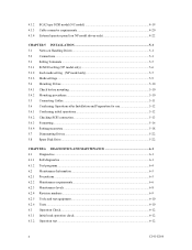
... Mounting procedures...5-10 5.5 Connecting Cables...5-11 5.6 Confirming Operations after Installation and Preparation for use 5-12 5.6.1 Confirming initial operations 5-12 5.6.2 Checking SCSI connection 5-13 5.6.3 Formatting ...5-16 5.6.4 Setting parameters ...5-18 5.7 Dismounting Drives...5-22 5.8 Spare Disk Drive ...5-22 CHAPTER 6 DIAGNOSTICS AND MAINTENANCE 6-1 6.1 Diagnostics ...6-1 6.1.1 Self-diagnostics ...6-1 6.1.2 Test programs...6-4 6.2 Maintenance Information 6-5 6.2.1 Precautions ...6-5 6.2.2 Maintenance requirements 6-6 6.2.3 Maintenance levels ...6-8 6.2.4 Revision numbers...
... Mounting procedures...5-10 5.5 Connecting Cables...5-11 5.6 Confirming Operations after Installation and Preparation for use 5-12 5.6.1 Confirming initial operations 5-12 5.6.2 Checking SCSI connection 5-13 5.6.3 Formatting ...5-16 5.6.4 Setting parameters ...5-18 5.7 Dismounting Drives...5-22 5.8 Spare Disk Drive ...5-22 CHAPTER 6 DIAGNOSTICS AND MAINTENANCE 6-1 6.1 Diagnostics ...6-1 6.1.1 Self-diagnostics ...6-1 6.1.2 Test programs...6-4 6.2 Maintenance Information 6-5 6.2.1 Precautions ...6-5 6.2.2 Maintenance requirements 6-6 6.2.3 Maintenance levels ...6-8 6.2.4 Revision numbers...
Manual/User Guide
Page 13
6.3.3 6.4 6.4.1 6.4.2 6.4.3 6.4.4 6.4.5 Diagnostic test ...6-12 Troubleshooting Procedures 6-13 Outline of troubleshooting procedures 6-13 Troubleshooting with disk drive replacement in the field 6-13 Troubleshooting at the repair site 6-15 Troubleshooting with parts replacement in the factory 6-16 Finding possibly faulty...1D-00): Disk read error 7-4 7.2.4 Sense data (5-2x-xx), (5-3D-00), (5-90-00), (B-47-xx), (B-49-00), (B-4D-xx) and (B-4E-00): SCSI interface error 7-4 APPENDIX A SETTING TERMINALS A-1 A.1 Setting Terminals (on NP model only A-2 APPENDIX B CONNECTOR SIGNAL ALLOCATION...
6.3.3 6.4 6.4.1 6.4.2 6.4.3 6.4.4 6.4.5 Diagnostic test ...6-12 Troubleshooting Procedures 6-13 Outline of troubleshooting procedures 6-13 Troubleshooting with disk drive replacement in the field 6-13 Troubleshooting at the repair site 6-15 Troubleshooting with parts replacement in the factory 6-16 Finding possibly faulty...1D-00): Disk read error 7-4 7.2.4 Sense data (5-2x-xx), (5-3D-00), (5-90-00), (B-47-xx), (B-49-00), (B-4D-xx) and (B-4E-00): SCSI interface error 7-4 APPENDIX A SETTING TERMINALS A-1 A.1 Setting Terminals (on NP model only A-2 APPENDIX B CONNECTOR SIGNAL ALLOCATION...
Manual/User Guide
Page 15
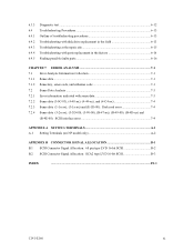
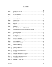
FIGURES Figure 1.1 Figure 1.2 Figure 1.3 Figure 1.4 page NC model drives outer view 1-6 NP model drives outer view 1-6 Disk/head configuration...1-7 System configuration ...1-9 Figure 3.1 Figure 3.2 Figure 3.3 Figure 3.4 Figure 3.5 Figure 3.6 Figure 3.7 Figure 3.8 Cylinder configuration...(2) ...4-9 Power on/off sequence (3) ...4-9 AC noise filter (recommended 4-11 NP connectors and terminals location 4-11 16-bit SCSI interface connector 4-12 Power supply connector (16-bit SCSI model 4-12 External operator panel connector (CN1 4-13 External operator panel connector (CN2 4-14 16-bit...
FIGURES Figure 1.1 Figure 1.2 Figure 1.3 Figure 1.4 page NC model drives outer view 1-6 NP model drives outer view 1-6 Disk/head configuration...1-7 System configuration ...1-9 Figure 3.1 Figure 3.2 Figure 3.3 Figure 3.4 Figure 3.5 Figure 3.6 Figure 3.7 Figure 3.8 Cylinder configuration...(2) ...4-9 Power on/off sequence (3) ...4-9 AC noise filter (recommended 4-11 NP connectors and terminals location 4-11 16-bit SCSI interface connector 4-12 Power supply connector (16-bit SCSI model 4-12 External operator panel connector (CN1 4-13 External operator panel connector (CN2 4-14 16-bit...
Manual/User Guide
Page 17
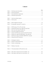
... model only 5-10 Table 6.1 Self-diagnostic functions ...6-1 Table 6.2 System-level field troubleshooting 6-14 Table 6.3 Disk drive troubleshooting ...6-15 Table 7.1 Definition of sense data ...7-3 Table A.1 CN2 setting terminal (on NP model drives only A-2 Table B.1 SCSI connector (68 pin type LVD 16-bit SCSI): CN1 B-2 Table B.2 SCSI connector (SCA2 type LVD 16-bit SCSI): CN1 B-3 C141-E166 xv
... model only 5-10 Table 6.1 Self-diagnostic functions ...6-1 Table 6.2 System-level field troubleshooting 6-14 Table 6.3 Disk drive troubleshooting ...6-15 Table 7.1 Definition of sense data ...7-3 Table A.1 CN2 setting terminal (on NP model drives only A-2 Table B.1 SCSI connector (68 pin type LVD 16-bit SCSI): CN1 B-2 Table B.2 SCSI connector (SCA2 type LVD 16-bit SCSI): CN1 B-3 C141-E166 xv
Manual/User Guide
Page 19
... and configuration of the IDD, allow the user to construct a high-performance reliable disk subsystem with large storage capacity. The MAP series disk drives support the Small Computer System Interface (SCSI) as the powerful command set of the MAP series intelligent disk drives (IDD). IDDs are high performance large capacity 3.5 type fixed disk...
... and configuration of the IDD, allow the user to construct a high-performance reliable disk subsystem with large storage capacity. The MAP series disk drives support the Small Computer System Interface (SCSI) as the powerful command set of the MAP series intelligent disk drives (IDD). IDDs are high performance large capacity 3.5 type fixed disk...
Manual/User Guide
Page 20
...standard 3.5 type fixed disk drive form factor, the IDD is available only with NP model. For the ultra SCSI model, number of connectable SCSI devices on the same SCSI bus is varied as follows. • 8-bit SCSI: 8 drives max. (option for NP model) • 16-bit SCSI: 16 drives max. (4) High speed ...data transfer Such a high data transfer rate on the SCSI bus is 320 MB/s ...
...standard 3.5 type fixed disk drive form factor, the IDD is available only with NP model. For the ultra SCSI model, number of connectable SCSI devices on the same SCSI bus is varied as follows. • 8-bit SCSI: 8 drives max. (option for NP model) • 16-bit SCSI: 16 drives max. (4) High speed ...data transfer Such a high data transfer rate on the SCSI bus is 320 MB/s ...
Manual/User Guide
Page 21
...to the disc media before you turn off the drive's power. Since the initiator can queue maximum 128 commands, and optimizes the issuing order of queued commands by the cable length, transmission characteristics of the SCSI bus and the connected SCSI device number. (5) Continuous block processing The addressing...-1] blocks in a command can be achieved, and IDD can access data by the response time of initiator and the length of the disk drive. (7) Cache feature After executing the READ command, the IDD reads automatically and stores (prefetches) the subsequent data blocks into the data buffer...
...to the disc media before you turn off the drive's power. Since the initiator can queue maximum 128 commands, and optimizes the issuing order of queued commands by the cable length, transmission characteristics of the SCSI bus and the connected SCSI device number. (5) Continuous block processing The addressing...-1] blocks in a command can be achieved, and IDD can access data by the response time of initiator and the length of the disk drive. (7) Cache feature After executing the READ command, the IDD reads automatically and stores (prefetches) the subsequent data blocks into the data buffer...
Manual/User Guide
Page 22
...to 528 bytes. The recoverable Error refered here is programmable, and can be specified at initializing with a multiple of four within the range of the drive might increase when the format would be modified from 512 bytes to the following values: 516 bytes, 520 bytes, 524 bytes, 528 bytes. 3.... The initiator software is released from errors in SCSI bus or the disk drive using the reserve and release functions. (10) Error recovery The IDD can try to the initiator after being corrected in a physical sequence ...
...to 528 bytes. The recoverable Error refered here is programmable, and can be specified at initializing with a multiple of four within the range of the drive might increase when the format would be modified from 512 bytes to the following values: 516 bytes, 520 bytes, 524 bytes, 528 bytes. 3.... The initiator software is released from errors in SCSI bus or the disk drive using the reserve and release functions. (10) Error recovery The IDD can try to the initiator after being corrected in a physical sequence ...
Manual/User Guide
Page 23
...15) Large capacity A large capacity can be used in the good space efficiency. (16) Start/Stop of spindle motor Using the SCSI command, the host system can be constructed in wide range of the IDD and function enhancing. This makes it ideal for MAP series... can start and stop the spindle motor. (17) Diagnosis The IDD has a diagnostic capability which checks internal controller functions and drive operations to be obtained from 3.5 type disk drives by dividing all cylinders into several partitions and changing the recording density on each partition (constant density recording).
...15) Large capacity A large capacity can be used in the good space efficiency. (16) Start/Stop of spindle motor Using the SCSI command, the host system can be constructed in wide range of the IDD and function enhancing. This makes it ideal for MAP series... can start and stop the spindle motor. (17) Diagnosis The IDD has a diagnostic capability which checks internal controller functions and drive operations to be obtained from 3.5 type disk drives by dividing all cylinders into several partitions and changing the recording density on each partition (constant density recording).
Manual/User Guide
Page 28
... for NP model, switch selectable) 16-bit SCSI:Selectable from 0 to 15 (switch selectable) 0 (fixed) 1-10 C141-E166 The initiator selects one SCSI device by specifying that operates as target is a single logical unit, the selectable number of disk drive is addressed in unit called as logical unit.... For input/output operation, a peripheral device attached to the SCSI bus that SCSI ID, then specifies the LUN to select the peripheral device for input/output operation. (1) SCSI bus configuration Up to eight SCSI devices operating ...
... for NP model, switch selectable) 16-bit SCSI:Selectable from 0 to 15 (switch selectable) 0 (fixed) 1-10 C141-E166 The initiator selects one SCSI device by specifying that operates as target is a single logical unit, the selectable number of disk drive is addressed in unit called as logical unit.... For input/output operation, a peripheral device attached to the SCSI bus that SCSI ID, then specifies the LUN to select the peripheral device for input/output operation. (1) SCSI bus configuration Up to eight SCSI devices operating ...
Manual/User Guide
Page 30
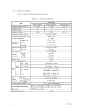
...: 3 m max (*6) Cable length: 1.5 m max (*7) LVD U160 Cable length: 25 m max (*8) Cable length: 12 m max (*9) Data transfer rate (*10) Disk drive SCSI Synchronous mode 64.1 to 528 byte (Fixed length) SCSI command specification SPI-4 (T10/1365D Rev.7), SAM-2 (T10/1157D Rev.20), SPC-2 (T10/1236D Rev.20), SBC (T10/996D Rev.8c... MAP3735NC/NP 73.50 GB 2 4 47,978 272,896 to 479,232 10,025±0.2% 2.99 msec 0.3 ms/0.5 ms 4.5 ms/5.0 ms 10.0 ms/11.0 ms 30 s typ. (60 s max.) 30 s typ. 32/34 MEEPRML 25.4 mm 101.6 mm 146.0 mm 0.75 kg 9.6 W Cable length: 6 m max MAP3367NC/NP 36.74 GB 1 2 48,104 ...
...: 3 m max (*6) Cable length: 1.5 m max (*7) LVD U160 Cable length: 25 m max (*8) Cable length: 12 m max (*9) Data transfer rate (*10) Disk drive SCSI Synchronous mode 64.1 to 528 byte (Fixed length) SCSI command specification SPI-4 (T10/1365D Rev.7), SAM-2 (T10/1157D Rev.20), SPC-2 (T10/1236D Rev.20), SBC (T10/996D Rev.8c... MAP3735NC/NP 73.50 GB 2 4 47,978 272,896 to 479,232 10,025±0.2% 2.99 msec 0.3 ms/0.5 ms 4.5 ms/5.0 ms 10.0 ms/11.0 ms 30 s typ. (60 s max.) 30 s typ. 32/34 MEEPRML 25.4 mm 101.6 mm 146.0 mm 0.75 kg 9.6 W Cable length: 6 m max MAP3367NC/NP 36.74 GB 1 2 48,104 ...
Manual/User Guide
Page 33
... are specified at all field sites C141-E166 2-5 Note: The MTBF is defined as: MTBF= Operating time (hours) at the drive connector side, during drive ready state. (*6) The terminator power pin (SCSI connector) which cannot be recovered within 63 retries and ECC correction should be recovered by alternate block assignments are applied for...
... are specified at all field sites C141-E166 2-5 Note: The MTBF is defined as: MTBF= Operating time (hours) at the drive connector side, during drive ready state. (*6) The terminator power pin (SCSI connector) which cannot be recovered within 63 retries and ECC correction should be recovered by alternate block assignments are applied for...
Manual/User Guide
Page 62
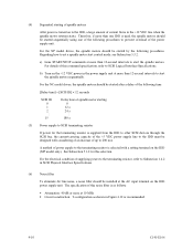
For the NP model drives, the spindle motors should be started by the following time. [Delay time] = [SCSI ID] × 12 seconds SCSI ID 0 1 2... 15 Delay time of spindle motor starting of spindle motors After power is turned on the IDD power supply unit. a) Issue START/STOP ...Attenuation: 40 dB or more at more than 12-second intervals to start the spindle motors. For details of this selection. For the NC model drives, the spindle motors should be started sequentially using one of the following procedures to prevent overload of the power supply unit. The specification of this...
For the NP model drives, the spindle motors should be started by the following time. [Delay time] = [SCSI ID] × 12 seconds SCSI ID 0 1 2... 15 Delay time of spindle motor starting of spindle motors After power is turned on the IDD power supply unit. a) Issue START/STOP ...Attenuation: 40 dB or more at more than 12-second intervals to start the spindle motors. For details of this selection. For the NC model drives, the spindle motors should be started sequentially using one of the following procedures to prevent overload of the power supply unit. The specification of this...
Manual/User Guide
Page 68
... to the IDD has been switched on (it is identical in indication to set up the SCSI ID by short circuiting CN1-A1 and CN1-A2.) c. CN1-A6 (reserved) These pins are short-circuited.) A signal for driving the LED is output. 74LS06 or equivalent 150 Ω (IDD) CN1-A2 IMPORTANT This signal...-9 and CN2-10 are temporarily driven at the GND level when the micro program reads the SCSI ID immediately after the power supply to the IDD has been switched on the front of the disk drive. The external LED is possible to the LED on (it is possible to the CN2-21...
... to the IDD has been switched on (it is identical in indication to set up the SCSI ID by short circuiting CN1-A1 and CN1-A2.) c. CN1-A6 (reserved) These pins are short-circuited.) A signal for driving the LED is output. 74LS06 or equivalent 150 Ω (IDD) CN1-A2 IMPORTANT This signal...-9 and CN2-10 are temporarily driven at the GND level when the micro program reads the SCSI ID immediately after the power supply to the IDD has been switched on the front of the disk drive. The external LED is possible to the LED on (it is possible to the CN2-21...
Manual/User Guide
Page 72
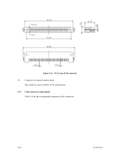
Figure 4.22 SCA2 type SCSI connector (3) Connector for external operator panel This connector is not available for NC model drives. 4.3.3 Cable connector requirements Table 4.2 lists the recommended components cable connection. 4-20 C141-E166
Figure 4.22 SCA2 type SCSI connector (3) Connector for external operator panel This connector is not available for NC model drives. 4.3.3 Cable connector requirements Table 4.2 lists the recommended components cable connection. 4-20 C141-E166
Manual/User Guide
Page 74
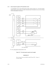
... -ID2 -ID3 GND S3 A8 A11 -LED +5V ID0 ID1 ID2 ID3 (LED) R Approx. 300Ω (*1) C N 2 S4 21 LED (+5V) 22 -LED (for 16-bit SCSI) (*1) For connecting the external LED to CN2. (LED) Figure 4.23 External operator panel circuit example IMPORTANT Do not connect the external LED to both CN1... and CN2. Since the external operator panel is shown in Figure 4.23. 4.3.4 External operator panel (on NP model drives only) A recommended circuit of them. 4-22 C141-E166
... -ID2 -ID3 GND S3 A8 A11 -LED +5V ID0 ID1 ID2 ID3 (LED) R Approx. 300Ω (*1) C N 2 S4 21 LED (+5V) 22 -LED (for 16-bit SCSI) (*1) For connecting the external LED to CN2. (LED) Figure 4.23 External operator panel circuit example IMPORTANT Do not connect the external LED to both CN1... and CN2. Since the external operator panel is shown in Figure 4.23. 4.3.4 External operator panel (on NP model drives only) A recommended circuit of them. 4-22 C141-E166
Manual/User Guide
Page 81
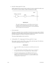
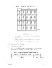
... power supply Refer to Table 5.2 for controlling the supply of SCSI terminator power from the drive to Figures 5.2 and 5.3. Table 5.1 SCSI ID setting (CN2 on the same SCSI bus. 2. Set the SCSI ID so that there are no duplicates between SCSI devices on NP model only) SCSI ID CN2 7-8 5-6 3-4 0 Open Open Open 1 Open Open Open 2 Open Open...
... power supply Refer to Table 5.2 for controlling the supply of SCSI terminator power from the drive to Figures 5.2 and 5.3. Table 5.1 SCSI ID setting (CN2 on the same SCSI bus. 2. Set the SCSI ID so that there are no duplicates between SCSI devices on NP model only) SCSI ID CN2 7-8 5-6 3-4 0 Open Open Open 1 Open Open Open 2 Open Open...
Manual/User Guide
Page 84
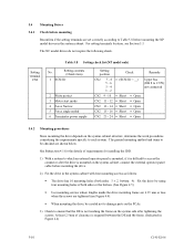
.... 3) Check to ensure that the DE is not touching the frame on the system side after the drive is difficult to Table 5.8 before mounting the drive. 2) Fix the drive in the system cabinet. Setting terminal CN2 Table 5.8 Setting check list (NP model only) No. At... (see Section 5.3. For setting terminals location, see Figure 4.4). • When mounting the drive, be checked are set correctly according to access the connector after tightening the screws. Setting contents (Check item) 1 SCSI ID 2 Write protect 3 Motor start mode 4 Force Narrow 5 Force single ended 6 ...
.... 3) Check to ensure that the DE is not touching the frame on the system side after the drive is difficult to Table 5.8 before mounting the drive. 2) Fix the drive in the system cabinet. Setting terminal CN2 Table 5.8 Setting check list (NP model only) No. At... (see Section 5.3. For setting terminals location, see Figure 4.4). • When mounting the drive, be checked are set correctly according to access the connector after tightening the screws. Setting contents (Check item) 1 SCSI ID 2 Write protect 3 Motor start mode 4 Force Narrow 5 Force single ended 6 ...


