
Manual/User Guide
Page 4
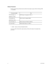
Document number T10/1236D Rev.20 [NCITS.351:2001] T10/996D Rev.8c [NCITS.306:1998] T10/1157D Rev.20 T10/1365D Rev.7 Title SCSI Primary Commands-2 (SPC-2) SCSI-3 Block Commands (SBC) SCSI Architecture Model-2 (SAM-2) SCSI Parallel Interface-4 (SPI-4) *1 ANSI = American National Standard Institute In case of conflict between this manual and any referenced document, this manual comply with the following ANSI (*1) standards. Related Standards Product specifications and functions described in this manual takes precedence. ii C141-E166
Document number T10/1236D Rev.20 [NCITS.351:2001] T10/996D Rev.8c [NCITS.306:1998] T10/1157D Rev.20 T10/1365D Rev.7 Title SCSI Primary Commands-2 (SPC-2) SCSI-3 Block Commands (SBC) SCSI Architecture Model-2 (SAM-2) SCSI Parallel Interface-4 (SPI-4) *1 ANSI = American National Standard Institute In case of conflict between this manual and any referenced document, this manual comply with the following ANSI (*1) standards. Related Standards Product specifications and functions described in this manual takes precedence. ii C141-E166
Manual/User Guide
Page 5
...error analysis and how analyze collected error information. Chapter 2 SPECIFICATIONS This chapter gives detailed specifications of fixed disk drives and their use the other manuals. Chapter 4 INSTALLATION ...REQUIREMENTS This chapter describes the basic physical and electrical requirements for setting device number and operation modes, mounting the disk drive, connecting the cables, and confirming drive operation. PREFACE This manual describes the MAP3147NC/NP, MAP3735NC/NP and MAP3367NC...
...error analysis and how analyze collected error information. Chapter 2 SPECIFICATIONS This chapter gives detailed specifications of fixed disk drives and their use the other manuals. Chapter 4 INSTALLATION ...REQUIREMENTS This chapter describes the basic physical and electrical requirements for setting device number and operation modes, mounting the disk drive, connecting the cables, and confirming drive operation. PREFACE This manual describes the MAP3147NC/NP, MAP3735NC/NP and MAP3367NC...
Manual/User Guide
Page 11
CONTENTS page CHAPTER 1 GENERAL DESCRIPTION 1-1 1.1 Standard Features ...1-2 1.2 Hardware Structure...1-6 1.3 System Configuration ...1-9 CHAPTER 2 SPECIFICATIONS 2-1 2.1 Hardware Specifications...2-1 2.1.1 Model name and order number 2-1 2.1.2 Function specifications...2-2 2.1.3 Environmental specifications 2-4 2.1.4 Error rate ...2-5 2.1.5 Reliability...2-5 2.2 SCSI Function Specifications 2-7 CHAPTER 3 DATA FORMAT 3-1 3.1 Data Space...3-1 3.1.1 Cylinder configuration...3-1 3.1.2 Alternate spare area...3-4 3.1.3 Track format...3-5 3.1.4 Sector format ...3-7 3.1.5 Format capacity ...
CONTENTS page CHAPTER 1 GENERAL DESCRIPTION 1-1 1.1 Standard Features ...1-2 1.2 Hardware Structure...1-6 1.3 System Configuration ...1-9 CHAPTER 2 SPECIFICATIONS 2-1 2.1 Hardware Specifications...2-1 2.1.1 Model name and order number 2-1 2.1.2 Function specifications...2-2 2.1.3 Environmental specifications 2-4 2.1.4 Error rate ...2-5 2.1.5 Reliability...2-5 2.2 SCSI Function Specifications 2-7 CHAPTER 3 DATA FORMAT 3-1 3.1 Data Space...3-1 3.1.1 Cylinder configuration...3-1 3.1.2 Alternate spare area...3-4 3.1.3 Track format...3-5 3.1.4 Sector format ...3-7 3.1.5 Format capacity ...
Manual/User Guide
Page 17
TABLES page Table 2.1 Model names and order numbers 2-1 Table 2.2 Function specifications ...2-2 Table 2.3 Environmental/power requirements 2-4 Table 2.4 SCSI function specifications...2-7 Table 3.1 Zone layout and track capacity 3-3 Table 3.4 Format capacity ...3-9 Table 4.1 Surface temperature check...6.1 Self-diagnostic functions ...6-1 Table 6.2 System-level field troubleshooting 6-14 Table 6.3 Disk drive troubleshooting ...6-15 Table 7.1 Definition of sense data ...7-3 Table A.1 CN2 setting terminal (on NP model drives only A-2 Table B.1 SCSI connector (68 pin type LVD 16-bit SCSI): CN1...
TABLES page Table 2.1 Model names and order numbers 2-1 Table 2.2 Function specifications ...2-2 Table 2.3 Environmental/power requirements 2-4 Table 2.4 SCSI function specifications...2-7 Table 3.1 Zone layout and track capacity 3-3 Table 3.4 Format capacity ...3-9 Table 4.1 Surface temperature check...6.1 Self-diagnostic functions ...6-1 Table 6.2 System-level field troubleshooting 6-14 Table 6.3 Disk drive troubleshooting ...6-15 Table 7.1 Definition of sense data ...7-3 Table A.1 CN2 setting terminal (on NP model drives only A-2 Table B.1 SCSI connector (68 pin type LVD 16-bit SCSI): CN1...
Manual/User Guide
Page 19
... in the ANSI SCSI SPI-4 [T10/1365D Rev.7] to the extent described in this manual. Refer to SCSI Logical Interface Specifications for details. The data format can be changed from the format at factory shipment by reinitializing with an embedded SCSI controller. The... the Small Computer System Interface (SCSI) as the powerful command set of the MAP series intelligent disk drives (IDD). IDDs are high performance large capacity 3.5 type fixed disk drives with the user's system. CHAPTER 1 GENERAL DESCRIPTION 1.1 Standard Features 1.2 Hardware Structure 1.3 System Configuration This ...
... in the ANSI SCSI SPI-4 [T10/1365D Rev.7] to the extent described in this manual. Refer to SCSI Logical Interface Specifications for details. The data format can be changed from the format at factory shipment by reinitializing with an embedded SCSI controller. The... the Small Computer System Interface (SCSI) as the powerful command set of the MAP series intelligent disk drives (IDD). IDDs are high performance large capacity 3.5 type fixed disk drives with the user's system. CHAPTER 1 GENERAL DESCRIPTION 1.1 Standard Features 1.2 Hardware Structure 1.3 System Configuration This ...
Manual/User Guide
Page 29
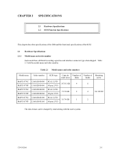
... and the functional specifications of Mounting (user area) disks heads screw 147.01 GB 4 8 73.50 GB 2 4 #6-32UNC 36.74 GB 1 2 The data format can be changed by reinitializing with the user's system. Table 2.1 lists the model name and order number. Table 2.1 Model names and order numbers Model name MAP3147NC MAP3147NP MAP3735NC MAP3735NP MAP3367NC MAP3367NP Order...
... and the functional specifications of Mounting (user area) disks heads screw 147.01 GB 4 8 73.50 GB 2 4 #6-32UNC 36.74 GB 1 2 The data format can be changed by reinitializing with the user's system. Table 2.1 lists the model name and order number. Table 2.1 Model names and order numbers Model name MAP3147NC MAP3147NP MAP3735NC MAP3735NP MAP3367NC MAP3367NP Order...
Manual/User Guide
Page 30
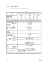
... typ. 32/34 MEEPRML 25.4 mm 101.6 mm 146.0 mm 0.75 kg 9.6 W Cable length: 6 m max MAP3367NC/NP 36.74 GB 1 2 48,104 Single- Table 2.2 Function specifications Item Formatted capacity/device (*1) Number of disks Number of heads Number of cylinders (*2) Formatted capacity/track (B) Number of the ...(*8) Cable length: 12 m max (*9) Data transfer rate (*10) Disk drive SCSI Synchronous mode 64.1 to 107.86 MB/s 320 MB/s max. Fast 10 SCSI Inter- 2.1.2 Function specifications Table 2.2 shows the function specifications of rotations min-1 (rpm) Average latency time Seek time (*3) (Read/...
... typ. 32/34 MEEPRML 25.4 mm 101.6 mm 146.0 mm 0.75 kg 9.6 W Cable length: 6 m max MAP3367NC/NP 36.74 GB 1 2 48,104 Single- Table 2.2 Function specifications Item Formatted capacity/device (*1) Number of disks Number of heads Number of cylinders (*2) Formatted capacity/track (B) Number of the ...(*8) Cable length: 12 m max (*9) Data transfer rate (*10) Disk drive SCSI Synchronous mode 64.1 to 107.86 MB/s 320 MB/s max. Fast 10 SCSI Inter- 2.1.2 Function specifications Table 2.2 shows the function specifications of rotations min-1 (rpm) Average latency time Seek time (*3) (Read/...
Manual/User Guide
Page 32
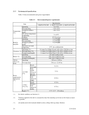
... Input power (about 80 (*5) IOPS) Ready +5 VDC ±5% (*6) Random W/R (about 80 IOPS) Ripple (*7) MAP3147NC/NP Specification MAP3735NC/NP 5 to 55°C -10 to 70°C -40 to 70°C MAP3367NC/NP 5 to 60°C 15°C/h or less 5 to 95%RH 5 to 95%RH 5 to 95%RH 29...-300 m to 3,000 m -300 m to 12,000 m 0.63 A 3.0 A 0.90 A 0.38 A 0.70 A +5 V/+12 V 250 mVp-p (*1) For detail condition, see Section 4.1. (*2) Vibration applied to the drive is measured at near the mounting screw hole on the frame as much as possible. (*3) At random seek write/read and default on retry setting...
... Input power (about 80 (*5) IOPS) Ready +5 VDC ±5% (*6) Random W/R (about 80 IOPS) Ripple (*7) MAP3147NC/NP Specification MAP3735NC/NP 5 to 55°C -10 to 70°C -40 to 70°C MAP3367NC/NP 5 to 60°C 15°C/h or less 5 to 95%RH 5 to 95%RH 5 to 95%RH 29...-300 m to 3,000 m -300 m to 12,000 m 0.63 A 3.0 A 0.90 A 0.38 A 0.70 A +5 V/+12 V 250 mVp-p (*1) For detail condition, see Section 4.1. (*2) Vibration applied to the drive is measured at near the mounting screw hole on the frame as much as possible. (*3) At random seek write/read and default on retry setting...
Manual/User Guide
Page 35
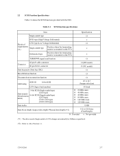
... 2.4 shows the SCSI functions provided with the IDD. Table 2.4 SCSI function specifications Item Specification Single-ended type Ο HVD type (High Voltage Differential) × Electrical LVD type (Low Voltage Differential) Ο requirements Single-ended type (*1) Position where the terminating ...
... 2.4 shows the SCSI functions provided with the IDD. Table 2.4 SCSI function specifications Item Specification Single-ended type Ο HVD type (High Voltage Differential) × Electrical LVD type (Low Voltage Differential) Ο requirements Single-ended type (*1) Position where the terminating ...
Manual/User Guide
Page 37
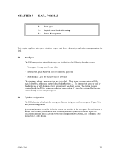
... 3.2 Logical Data Block Addressing 3.3 Defect Management This chapter explains data space definition, logical data block addressing, and defect management on or during the execution of a specific command, but user can be accessed with the logical data block addressing method described in Section 3.2.
... 3.2 Logical Data Block Addressing 3.3 Defect Management This chapter explains data space definition, logical data block addressing, and defect management on or during the execution of a specific command, but user can be accessed with the logical data block addressing method described in Section 3.2.
Manual/User Guide
Page 48
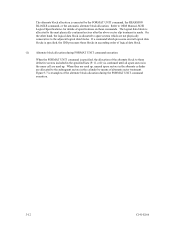
... allocation is examples of the alternate block allocation during FORMAT UNIT command execution When the FORMAT UNIT command is allocated to OEM Manual-SCSI Logical Specifications-for details of specifications on these commands.
... allocation is examples of the alternate block allocation during FORMAT UNIT command execution When the FORMAT UNIT command is allocated to OEM Manual-SCSI Logical Specifications-for details of specifications on these commands.
Manual/User Guide
Page 56
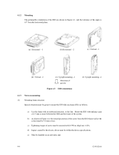
... frame of the system. d) Impact caused by the electric driver must be handled on mounting (1) Mounting frame structure Special attention must be within the device specifications.
... frame of the system. d) Impact caused by the electric driver must be handled on mounting (1) Mounting frame structure Special attention must be within the device specifications.
Manual/User Guide
Page 58
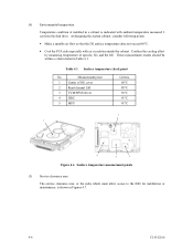
Measurement point 1 Center of specific ICs and the DE. These measurement results should be within a criteria listed in Figures 4.7. 4-6 C141-E166 At designing the system cabinet, consider following points. • ... so that the DE surface temperature does not exceed 60°C. • Cool the PCA side especially with ambient temperature measured 3 cm from the disk drive. Confirm the cooling effect by measuring temperature of DE cover 2 Read channel LSI 3 VCM/SPM Driver 4 HDC 5 MPU Criteria 60°C 88°C 92°...
Measurement point 1 Center of specific ICs and the DE. These measurement results should be within a criteria listed in Figures 4.7. 4-6 C141-E166 At designing the system cabinet, consider following points. • ... so that the DE surface temperature does not exceed 60°C. • Cool the PCA side especially with ambient temperature measured 3 cm from the disk drive. Confirm the cooling effect by measuring temperature of DE cover 2 Read channel LSI 3 VCM/SPM Driver 4 HDC 5 MPU Criteria 60°C 88°C 92°...
Manual/User Guide
Page 62
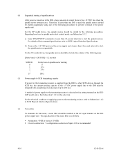
...on the IDD power supply unit. For the electrical condition of this command specification, refer to start the spindle motors sequentially. Therefore, if more than 12-second intervals to SCSI Logical Interface Specifications. A method of power supply to the terminating resistor is used, the ... 5.3.2. (4) Sequential starting 0 12 s 24 ...s 180 s (5) Power supply to set a spindle motor start the spindle motors. The specification of this selection. For the NP model drives, the spindle motors should be started after a delay of the following procedures. For the NC model...
...on the IDD power supply unit. For the electrical condition of this command specification, refer to start the spindle motors sequentially. Therefore, if more than 12-second intervals to SCSI Logical Interface Specifications. A method of power supply to the terminating resistor is used, the ... 5.3.2. (4) Sequential starting 0 12 s 24 ...s 180 s (5) Power supply to set a spindle motor start the spindle motors. The specification of this selection. For the NP model drives, the spindle motors should be started after a delay of the following procedures. For the NC model...
Manual/User Guide
Page 64
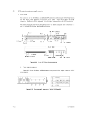
For details on the SCSI connector. Figure 4.15 Power supply connector (16-bit SCSI model) 4-12 C141-E166 See Section B.1 in the SCSI Physical Interface Specifications. (2) SCSI connector and power supply connector a. 16-bit SCSI The connector for the signal assignments on the physical/electrical requirements of DC power supply. Power ...
For details on the SCSI connector. Figure 4.15 Power supply connector (16-bit SCSI model) 4-12 C141-E166 See Section B.1 in the SCSI Physical Interface Specifications. (2) SCSI connector and power supply connector a. 16-bit SCSI The connector for the signal assignments on the physical/electrical requirements of DC power supply. Power ...
Manual/User Guide
Page 71
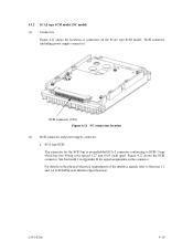
See Section B.2 in SCSI Physical Interface Specifications. C141-E166 4-19 Figure 4.22 shows the SCSI connector. SCA type SCSI The connector for signal assignments on the SCA2 type SCSI model. For details ...
See Section B.2 in SCSI Physical Interface Specifications. C141-E166 4-19 Figure 4.22 shows the SCSI connector. SCA type SCSI The connector for signal assignments on the SCA2 type SCSI model. For details ...
Manual/User Guide
Page 73
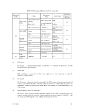
... HIROSE ELECTRIC A3B-2630SCC HIROSE ELECTRIC (AWG26 to 36) FCN-723J024/2M FUJITSU TAKAMIZAWA FCN-723J-G/AM FUJITSU TAKAMIZAWA (AWG28) 71780-003 FCI Reference (Figures 4.25 and 4.30) S1 S2 S3 S4 (1) SCSI cable See Section 1.3, "Physical Requirements", and Section 1.4, "Electrical Requirements", in SCSI Physical Interface Specifications. (2) Power cable IDDs must be star-connected...
... HIROSE ELECTRIC A3B-2630SCC HIROSE ELECTRIC (AWG26 to 36) FCN-723J024/2M FUJITSU TAKAMIZAWA FCN-723J-G/AM FUJITSU TAKAMIZAWA (AWG28) 71780-003 FCI Reference (Figures 4.25 and 4.30) S1 S2 S3 S4 (1) SCSI cable See Section 1.3, "Physical Requirements", and Section 1.4, "Electrical Requirements", in SCSI Physical Interface Specifications. (2) Power cable IDDs must be star-connected...
Manual/User Guide
Page 75
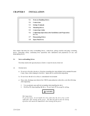
... and remain hot immediately after turning off the power. Do not touch PCAs except for use, and dismounting drives. 5.1 Notes on Handling Drives The items listed in the specifications in Table 2.1 must be careful when unpacking. C141-E166 5-1 Especially be strictly observed. (1) General notes ...a) Do not give the drive shocks or vibrations exceeding the value defined in the standard because it may destroy the CMOS semiconductors in ...
... and remain hot immediately after turning off the power. Do not touch PCAs except for use, and dismounting drives. 5.1 Notes on Handling Drives The items listed in the specifications in Table 2.1 must be careful when unpacking. C141-E166 5-1 Especially be strictly observed. (1) General notes ...a) Do not give the drive shocks or vibrations exceeding the value defined in the standard because it may destroy the CMOS semiconductors in ...
Manual/User Guide
Page 82
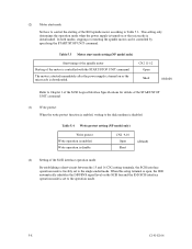
... the power supply is turned on or the microcode is downloaded. CN2 11-12 Open Short (default) Refer to Chapter 3 of the SCSI Logical Interface Specifications for details of the IDD spindle motor according to the operation mode. 5-8 C141-E166 When this setup terminal is open, the IDD automatically identifies the...
... the power supply is turned on or the microcode is downloaded. CN2 11-12 Open Short (default) Refer to Chapter 3 of the SCSI Logical Interface Specifications for details of the IDD spindle motor according to the operation mode. 5-8 C141-E166 When this setup terminal is open, the IDD automatically identifies the...
Manual/User Guide
Page 83
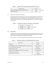
... restricted Not sent from IDD 250 ms 0 sec (NP) 12 sec × SCSI ID (NC) C141-E166 5-9 Refer to Section 3.1.4 of the SCSI Logical Interface Specifications for the IDD SCSI interface is not connected to the 8-bit bus mode. Table 5.7 Default mode settings (by specifying the CHANGE DEFINITION command. This setup...
... restricted Not sent from IDD 250 ms 0 sec (NP) 12 sec × SCSI ID (NC) C141-E166 5-9 Refer to Section 3.1.4 of the SCSI Logical Interface Specifications for the IDD SCSI interface is not connected to the 8-bit bus mode. Table 5.7 Default mode settings (by specifying the CHANGE DEFINITION command. This setup...
