User manual
Page 6
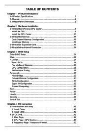
... 11 Dual Channel Memory Configuration 11 Installing a Memory 11 2-3 Install an Expansion Card 13 2-4 Install other Internal Connectors 14 Chapter 3 BIOS Setup Enter BIOS Setup 21 Main...22 F-Center...24 Smart BIOS 24 Fox Intelligent Stepping 25 CPU Configuration 26 Performance Tuning 27 Advanced...29 North Bridge 29 Onboard Device Configuration 30 SATA...
... 11 Dual Channel Memory Configuration 11 Installing a Memory 11 2-3 Install an Expansion Card 13 2-4 Install other Internal Connectors 14 Chapter 3 BIOS Setup Enter BIOS Setup 21 Main...22 F-Center...24 Smart BIOS 24 Fox Intelligent Stepping 25 CPU Configuration 26 Performance Tuning 27 Advanced...29 North Bridge 29 Onboard Device Configuration 30 SATA...

User manual
Page 7
... Storage Technology enterprise 67 5-3 Steps to Non-RAID 86 5. Reset Disks to Install Serial ATA Hard Disks 67 5-4 Create a RAID driver diskette 68 5-5 BIOS Configuration 69 5-6 Create RAID in BIOS 69 1. Recovery Volume Options 91 6. Limit Setting 50 5. Configure 59 4. Delete RAID Volume 85 4. Fan Control 53 4-3 FOX LiveUpdate 54 1. Exit RAID...
... Storage Technology enterprise 67 5-3 Steps to Non-RAID 86 5. Reset Disks to Install Serial ATA Hard Disks 67 5-4 Create a RAID driver diskette 68 5-5 BIOS Configuration 69 5-6 Create RAID in BIOS 69 1. Recovery Volume Options 91 6. Limit Setting 50 5. Configure 59 4. Delete RAID Volume 85 4. Fan Control 53 4-3 FOX LiveUpdate 54 1. Exit RAID...

User manual
Page 15
... the CPU specifications. The CPU cannot be set the frequency beyond hardware specifications since it does not meet the standard requirements for HT Technology ■ A BIOS that supports HT Technology and has it enabled Install the CPU Locate the alignment keys on the motherboard CPU socket and the notches on the...
... the CPU specifications. The CPU cannot be set the frequency beyond hardware specifications since it does not meet the standard requirements for HT Technology ■ A BIOS that supports HT Technology and has it enabled Install the CPU Locate the alignment keys on the motherboard CPU socket and the notches on the...
User manual
Page 20
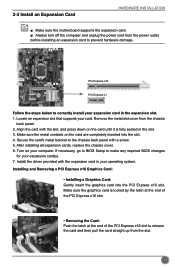
...the graphics card is fully seated in the expansion slot. 1. PCI Express x16 PCI Express x1 Follow the steps below to make any required BIOS changes for your expansion card in the slot. 3. After installing all expansion cards, replace the chassis cover. 6. Install the driver provided with... a screw. 5. If necessary, go to BIOS Setup to correctly install your expansion card(s). 7. Remove the metal slot cover from the power outlet before installing an expansion card to release the...
...the graphics card is fully seated in the expansion slot. 1. PCI Express x16 PCI Express x1 Follow the steps below to make any required BIOS changes for your expansion card in the slot. 3. After installing all expansion cards, replace the chassis cover. 6. Install the driver provided with... a screw. 5. If necessary, go to BIOS Setup to correctly install your expansion card(s). 7. Remove the metal slot cover from the power outlet before installing an expansion card to release the...
User manual
Page 24
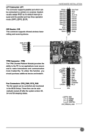
...) provides the ability to the PC to run applications more secure and to a printer or a scanner. These fans can be controlled and monitored in the BIOS Setup. HARDWARE INSTALLATION Strobe Data it [0] Data it [1] Data it [2] Data it [3] Data it [4] Data it [5] Data it [6] Data it 's default interrupt request and the...
...) provides the ability to the PC to run applications more secure and to a printer or a scanner. These fans can be controlled and monitored in the BIOS Setup. HARDWARE INSTALLATION Strobe Data it [0] Data it [1] Data it [2] Data it [3] Data it [4] Data it [5] Data it [6] Data it 's default interrupt request and the...
User manual
Page 25
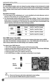
... ESD (Electrical Static Discharge) problem. However, in this motherboard to configure new system as BIOS data, date, time information, hardware password...etc.). Clear CMOS data is simply labeled as "1". 2. Go to BIOS Setup to modify them. It can change the jumper settings on this manual, pin 1... is the fast way to go back to factory default when the BIOS settings were mistakenly modified. Remove jumper cap from the power outlet. 2. "Closed" means placing a jumper cap on . 18 The following ...
... ESD (Electrical Static Discharge) problem. However, in this motherboard to configure new system as BIOS data, date, time information, hardware password...etc.). Clear CMOS data is simply labeled as "1". 2. Go to BIOS Setup to modify them. It can change the jumper settings on this manual, pin 1... is the fast way to go back to factory default when the BIOS settings were mistakenly modified. Remove jumper cap from the power outlet. 2. "Closed" means placing a jumper cap on . 18 The following ...
User manual
Page 26
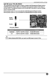
... 2 (Default) 3 1 Disable 2 3 PCH_ME_ENABLE Definition 1-2(default) 2-3 Description Set Pin 1 and Pin 2 closed Set Pin 2 and Pin 3 closed Function Enable ME function Disable ME function N Before flashing BIOS ROM, you can enable the Intel® Management Engine function. HARDWARE INSTALLATION Intel® ME Jumper: PCH_ME_ENABLE This motherboard uses this jumper to improve management...
... 2 (Default) 3 1 Disable 2 3 PCH_ME_ENABLE Definition 1-2(default) 2-3 Description Set Pin 1 and Pin 2 closed Set Pin 2 and Pin 3 closed Function Enable ME function Disable ME function N Before flashing BIOS ROM, you can enable the Intel® Management Engine function. HARDWARE INSTALLATION Intel® ME Jumper: PCH_ME_ENABLE This motherboard uses this jumper to improve management...
User manual
Page 27
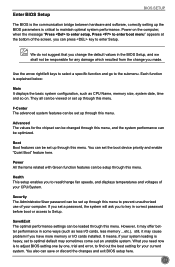
This chapter includes the following cases occur: 1. Chapter 3 BIOS Setup This chapter tells how to change system settings through the BIOS Setup menus. You want to change the default CMOS settings. An error message appears on the screen during the system Power On Self Test (POST) process. 2. You have to run the Setup Program when the following information : ■ Enter BIOS Setup ■ Main ■ F-Center ■ Advanced ■ Boot ■ Power ■ Health ■ Security ■ Save & Exit Detailed descriptions of the BIOS parameters are also provided.
This chapter includes the following cases occur: 1. Chapter 3 BIOS Setup This chapter tells how to change system settings through the BIOS Setup menus. You want to change the default CMOS settings. An error message appears on the screen during the system Power On Self Test (POST) process. 2. You have to run the Setup Program when the following information : ■ Enter BIOS Setup ■ Main ■ F-Center ■ Advanced ■ Boot ■ Power ■ Health ■ Security ■ Save & Exit Detailed descriptions of the BIOS parameters are also provided.
User manual
Page 28
... menu. Use the arrow right/left keys to select a specific function and go to Setup. F-Center The advanced system features can be set up the BIOS parameters is explained below: Main It displays the basic system configuration, such as less I /O cards installed. You also can be optimized. They all can ...your current system. We do not suggest that you change you set up through this menu. It means, if your system loading is to adjust BIOS setting one by one, trial and error, to enter boot menu" appears at the bottom of your CPU/System. You can be set up ...
... menu. Use the arrow right/left keys to select a specific function and go to Setup. F-Center The advanced system features can be set up the BIOS parameters is explained below: Main It displays the basic system configuration, such as less I /O cards installed. You also can be optimized. They all can ...your current system. We do not suggest that you change you set up through this menu. It means, if your system loading is to adjust BIOS setting one by one, trial and error, to enter boot menu" appears at the bottom of your CPU/System. You can be set up ...
User manual
Page 29
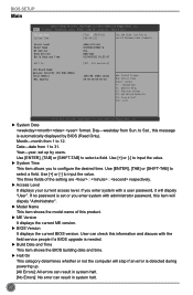
...& Exit ESC: Exit Version 2.12.1219. to Sat., this product. ► ME Version It displays the current ME version. ► BIOS Version It displays the current BIOS version. Month-month from 1 to select a field. Use [ENTER], [TAB] or [SHIFT-TAB] to 12. If you enter system...is automatically displayed by users. The three fields of this message is detected during powering up by BIOS (Read Only). Access Level Model Name ME Version BIOS Version Build Date and Time Administrator H77MXV/H77MXV-D N/A BB4F1A01 01/04/2012 14:27:07 Halt On [All, but keyboard] CPU Brand...
...& Exit ESC: Exit Version 2.12.1219. to Sat., this product. ► ME Version It displays the current ME version. ► BIOS Version It displays the current BIOS version. Month-month from 1 to select a field. Use [ENTER], [TAB] or [SHIFT-TAB] to 12. If you enter system...is automatically displayed by users. The three fields of this message is detected during powering up by BIOS (Read Only). Access Level Model Name ME Version BIOS Version Build Date and Time Administrator H77MXV/H77MXV-D N/A BB4F1A01 01/04/2012 14:27:07 Halt On [All, but keyboard] CPU Brand...

User manual
Page 30
BIOS SETUP [All, but keyboard]: All errors but keyboard can result in your system before powering on. ► MAC Address This item displays the onboard LAN MAC address. 23 The size is depending on how many memory modules are installed in system halt. ► CPU Brand Name It displays the current CPU name. ► Total Memory This item displays the total memory size.
BIOS SETUP [All, but keyboard]: All errors but keyboard can result in your system before powering on. ► MAC Address This item displays the onboard LAN MAC address. 23 The size is depending on how many memory modules are installed in system halt. ► CPU Brand Name It displays the current CPU name. ► Total Memory This item displays the total memory size.
User manual
Page 31
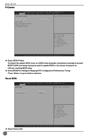
.... F1: General Help F2: Previous Values F3: Optimized Defaults F4: Save & Exit ESC: Exit Version 2.14.1219. F-Center Smart BIOS Smart Power LED Settings Smart Power LED Smart Boot Menu [Disabled] [Enabled] → ←: Select Screen ↑ ↓: Select... Select +/-: Change Opt. Main AFd-vCaenctedr Advanced Boot Power Health Security Save & Exit Fox Control Center Super BIOS Protection Settings Super BIOS Protect [Disabled] ▶ Smart BIOS ▶ Fox Intelligent Stepping ▶ CPU Configuration ▶ Performance Tuning → ←: Select Screen &#...
.... F1: General Help F2: Previous Values F3: Optimized Defaults F4: Save & Exit ESC: Exit Version 2.14.1219. F-Center Smart BIOS Smart Power LED Settings Smart Power LED Smart Boot Menu [Disabled] [Enabled] → ←: Select Screen ↑ ↓: Select... Select +/-: Change Opt. Main AFd-vCaenctedr Advanced Boot Power Health Security Save & Exit Fox Control Center Super BIOS Protection Settings Super BIOS Protect [Disabled] ▶ Smart BIOS ▶ Fox Intelligent Stepping ▶ CPU Configuration ▶ Performance Tuning → ←: Select Screen &#...
User manual
Page 32
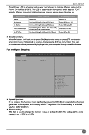
BIOS SETUP Smart Power LED is selected, then pressing [F7] has no function. C opyright (C) 2011 American Megatrends, Inc. F-Center Spread Spectrum Memory Voltage [Enabled] [Default] → &#...
BIOS SETUP Smart Power LED is selected, then pressing [F7] has no function. C opyright (C) 2011 American Megatrends, Inc. F-Center Spread Spectrum Memory Voltage [Enabled] [Default] → &#...
User manual
Page 33
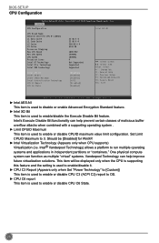
... (i.e. One physical compute system can function as multiple "virtual" systems. Vanderpool Technology can help improve future virtualization solutions. Intel® Vanderpool Technology) allows a platform to 3. BIOS SETUP CPU Configuration Aptio Setup Utility - F-Center CPU Configuration Intel AES-NI CPU Brand Name: Genuine Intel(R) CPU @ 1.80GHz L1 Data Cache L1 Code Cache...
... (i.e. One physical compute system can function as multiple "virtual" systems. Vanderpool Technology can help improve future virtualization solutions. Intel® Vanderpool Technology) allows a platform to 3. BIOS SETUP CPU Configuration Aptio Setup Utility - F-Center CPU Configuration Intel AES-NI CPU Brand Name: Genuine Intel(R) CPU @ 1.80GHz L1 Data Cache L1 Code Cache...
User manual
Page 34
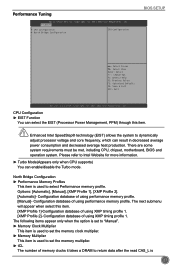
... & Exit ESC: Exit Version 2.14.1219. There are some system requirements must be met, including CPU, chipset, motherboard, BIOS and operation system. Configuration database of using performance memory profile. [Manual]- Configuration database of using performance memory profile. The next submenu... Memory Profiles This item is 27 F-Center ▶ CPU Configuration ▶ North Bridge Configuration CPU Configuration BIOS SETUP → ←: Select Screen ↑ ↓: Select Item Enter: Select +/-: Change Opt. Copyright (C) 2011 American Megatrends, Inc.
... & Exit ESC: Exit Version 2.14.1219. There are some system requirements must be met, including CPU, chipset, motherboard, BIOS and operation system. Configuration database of using performance memory profile. [Manual]- Configuration database of using performance memory profile. The next submenu... Memory Profiles This item is 27 F-Center ▶ CPU Configuration ▶ North Bridge Configuration CPU Configuration BIOS SETUP → ←: Select Screen ↑ ↓: Select Item Enter: Select +/-: Change Opt. Copyright (C) 2011 American Megatrends, Inc.
User manual
Page 35
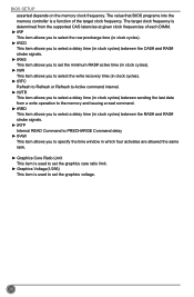
The target clock frequency is used to set the graphics voltage. 28 The value that BIOS programs into the memory controller is a function of each DIMM. ► tRP This item allows you to select the row precharge time (in clock cycles). &#... care ratio limit. ► Graphics Voltage(1/256) This item is determined from the supported CAS latencies at given clock frequencies of the target clock frequency. BIOS SETUP asserted depends on the memory clock frequency.
The target clock frequency is used to set the graphics voltage. 28 The value that BIOS programs into the memory controller is a function of each DIMM. ► tRP This item allows you to select the row precharge time (in clock cycles). &#... care ratio limit. ► Graphics Voltage(1/256) This item is determined from the supported CAS latencies at given clock frequencies of the target clock frequency. BIOS SETUP asserted depends on the memory clock frequency.

User manual
Page 36
... Save & Exit ▶ North Bridge ▶ ME Subsystem ▶ Onboard Device Configuration ▶ SATA Configuration ▶ Super IO Configuration ▶ Trusted Computing North Bridge Parameters BIOS SETUP → ←: Select Screen ↑ ↓: Select Item Enter: Select +/-: Change Opt. Manual the integrated graphics controller. 29 Advanced Aptio Setup Utility - C opyright (C) 2011...
... Save & Exit ▶ North Bridge ▶ ME Subsystem ▶ Onboard Device Configuration ▶ SATA Configuration ▶ Super IO Configuration ▶ Trusted Computing North Bridge Parameters BIOS SETUP → ←: Select Screen ↑ ↓: Select Item Enter: Select +/-: Change Opt. Manual the integrated graphics controller. 29 Advanced Aptio Setup Utility - C opyright (C) 2011...

User manual
Page 37
...-d) can help end users improve security and reliability of the systems and also improve performance of page-locked graphics memory is allocated during driver initialization. BIOS SETUP ► UMA Frame buffer Size Allocates system memory for use as the primary boot device. ► VT-d This item is used to enable the...
...-d) can help end users improve security and reliability of the systems and also improve performance of page-locked graphics memory is allocated during driver initialization. BIOS SETUP ► UMA Frame buffer Size Allocates system memory for use as the primary boot device. ► VT-d This item is used to enable the...
User manual
Page 38
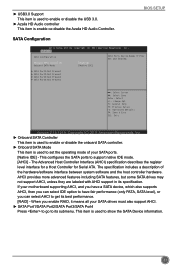
... Port2:Not Present ▶ SATA Port3:Not Present ▶ SATA Port4:Not Present → ←: Select Screen ↑ ↓: Select Item Enter: Select +/-: Change Opt. BIOS SETUP SATA Configuration Aptio Setup Utility - Copyright (C) 2011 American Megatrends, Inc. ► Onboard SATA Controller This item is used to enable or disable the onboard...
... Port2:Not Present ▶ SATA Port3:Not Present ▶ SATA Port4:Not Present → ←: Select Screen ↑ ↓: Select Item Enter: Select +/-: Change Opt. BIOS SETUP SATA Configuration Aptio Setup Utility - Copyright (C) 2011 American Megatrends, Inc. ► Onboard SATA Controller This item is used to enable or disable the onboard...
User manual
Page 39
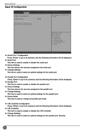
BIOS SETUP Super IO Configuration Aptio Setup Utility - Copyright (C) 2011 American Megatrends, Inc. ► Serial Port 1 Configuration Press to go to its submenu and the following ...
BIOS SETUP Super IO Configuration Aptio Setup Utility - Copyright (C) 2011 American Megatrends, Inc. ► Serial Port 1 Configuration Press to go to its submenu and the following ...


