User manual
Page 5
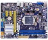
... a PCI Express x16 graphics card installed in contact with the connectors on the motherboard, make sure the power supply AC input voltage setting has been configured to the local standard. ■ To prevent damage to the motherboard, do not allow screws to high temperature. Technical Support Website: http://www.foxconnchannel.com Support Website: http://www.foxconnsupport.com Worldwide online contact Support: http://www.foxconnsupport.com/inquiry.aspx CPU Support List: http...
... a PCI Express x16 graphics card installed in contact with the connectors on the motherboard, make sure the power supply AC input voltage setting has been configured to the local standard. ■ To prevent damage to the motherboard, do not allow screws to high temperature. Technical Support Website: http://www.foxconnchannel.com Support Website: http://www.foxconnsupport.com Worldwide online contact Support: http://www.foxconnsupport.com/inquiry.aspx CPU Support List: http...

User manual
Page 7
...Reset Disks to Install Serial ATA Hard Disks 67 5-4 Create a RAID driver diskette 68 5-5 BIOS Configuration 69 5-6 Create RAID in BIOS 69 1. Delete RAID Volume 85 4. Voltage Page - Exit RAID BIOS 92 5-7 Install a New Windows XP 93 Limit Setting 50 5. Fan Control 53 4-3 FOX LiveUpdate 54 1. Voltage Control (Optional 53 6. Recovery Volume Options 91 6. Configure 59 4. Fan Page - Local Update 54 2. Online Update 56 3. Enter RAID BIOS Setup 69 2. 4. About & Help 61 4-4 FOX LOGO 62 4-5 FOX DMI 63 4-6 Smart charger 63 Chapter 5 RAID Configuration 5-1 RAID...
...Reset Disks to Install Serial ATA Hard Disks 67 5-4 Create a RAID driver diskette 68 5-5 BIOS Configuration 69 5-6 Create RAID in BIOS 69 1. Delete RAID Volume 85 4. Voltage Page - Exit RAID BIOS 92 5-7 Install a New Windows XP 93 Limit Setting 50 5. Fan Control 53 4-3 FOX LiveUpdate 54 1. Voltage Control (Optional 53 6. Recovery Volume Options 91 6. Configure 59 4. Fan Page - Local Update 54 2. Online Update 56 3. Enter RAID BIOS Setup 69 2. 4. About & Help 61 4-4 FOX LOGO 62 4-5 FOX DMI 63 4-6 Smart charger 63 Chapter 5 RAID Configuration 5-1 RAID...
User manual
Page 12
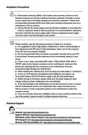
...the monitor being used. 5. USB 3.0 Port The USB port supports the USB 3.0/2.0/1.0 specification. HDMI Port The HDMI (High-Definition Multimedia Interface) provides an all-digital audio/video interface to this port for USB devices such as an USB keyboard/mouse, USB printer, USB flash drive and etc. But you need to connect external display devices, such as an USB keyboard/mouse, USB printer, USB flash drive and etc. 3. DVI_D Port The DVI-D port supports DVI-D specification. Use this port to install the USB 3.0 driver in the Driver CD before using it. 5 VGA Port Use this port for USB...
...the monitor being used. 5. USB 3.0 Port The USB port supports the USB 3.0/2.0/1.0 specification. HDMI Port The HDMI (High-Definition Multimedia Interface) provides an all-digital audio/video interface to this port for USB devices such as an USB keyboard/mouse, USB printer, USB flash drive and etc. But you need to connect external display devices, such as an USB keyboard/mouse, USB printer, USB flash drive and etc. 3. DVI_D Port The DVI-D port supports DVI-D specification. Use this port to install the USB 3.0 driver in the Driver CD before using it. 5 VGA Port Use this port for USB...
User manual
Page 20
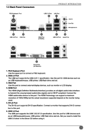
... from the chassis back panel. 2. If necessary, go to BIOS Setup to prevent hardware damage. Install the driver provided with the expansion card in the expansion slot. 1. Remove the metal slot cover from the slot. 13 2-3 Install an Expansion Card HARDWARE INSTALLATION ■ Make sure the motherboard supports the expansion card. ■ Always turn off the computer and unplug the power cord from the power outlet before installing an expansion card to...
... from the chassis back panel. 2. If necessary, go to BIOS Setup to prevent hardware damage. Install the driver provided with the expansion card in the expansion slot. 1. Remove the metal slot cover from the slot. 13 2-3 Install an Expansion Card HARDWARE INSTALLATION ■ Make sure the motherboard supports the expansion card. ■ Always turn off the computer and unplug the power cord from the power outlet before installing an expansion card to...

User manual
Page 22
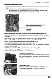
... chassis. The system can be connected to be turned on the front panel of the chassis. HARDWARE INSTALLATION 12 + + HDD-LED - This 2-pin connector is off rather than using the power supply button. It indicates the active status of this switch allows the system to a security switch on . Reset Switch (RESET-SW) Attach the connector to connect speaker of the case; The Power LED indicates the system's status. When the system gets into sleep mode (S1) , the LED...
... chassis. The system can be connected to be turned on the front panel of the chassis. HARDWARE INSTALLATION 12 + + HDD-LED - This 2-pin connector is off rather than using the power supply button. It indicates the active status of this switch allows the system to a security switch on . Reset Switch (RESET-SW) Attach the connector to connect speaker of the case; The Power LED indicates the system's status. When the system gets into sleep mode (S1) , the LED...
User manual
Page 25
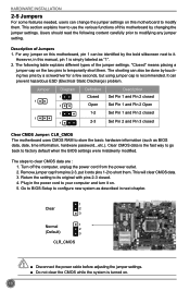
... clear CMOS data. 3. HARDWARE INSTALLATION 2-5 Jumpers For some features needed, users can change the jumper settings on this motherboard to its original with pins 2-3 closed Clear CMOS Jumper: CLR_CMOS The motherboard uses CMOS RAM to use the various functions of this motherboard by changing the jumper settings. Description of Jumpers 1. Return the setting to modify them . This section explains how to store the basic hardware information (such as BIOS data, date, time information, hardware password...etc.). Jumper 1 1 Diagram...
... clear CMOS data. 3. HARDWARE INSTALLATION 2-5 Jumpers For some features needed, users can change the jumper settings on this motherboard to its original with pins 2-3 closed Clear CMOS Jumper: CLR_CMOS The motherboard uses CMOS RAM to use the various functions of this motherboard by changing the jumper settings. Description of Jumpers 1. Return the setting to modify them . This section explains how to store the basic hardware information (such as BIOS data, date, time information, hardware password...etc.). Jumper 1 1 Diagram...
User manual
Page 26
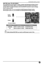
... flashing BIOS ROM, you can enable the Intel® Management Engine function. It provides latest IT management features such as Intel® AMT, that allows to pins 2-3 first. Intel® Management Engine (ME) is an embedded microcontroller located in Intel chipset. Set the jumper to enable or disable Intel® Management Engine function. CAUTIO 19 HARDWARE INSTALLATION Intel® ME Jumper: PCH_ME_ENABLE This motherboard uses...
... flashing BIOS ROM, you can enable the Intel® Management Engine function. It provides latest IT management features such as Intel® AMT, that allows to pins 2-3 first. Intel® Management Engine (ME) is an embedded microcontroller located in Intel chipset. Set the jumper to enable or disable Intel® Management Engine function. CAUTIO 19 HARDWARE INSTALLATION Intel® ME Jumper: PCH_ME_ENABLE This motherboard uses...
User manual
Page 28
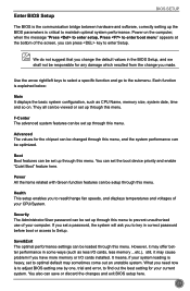
... screen, you have more memory or I/O cards installed. Save&Exit The optimal performance settings can be loaded through this menu, and the system performance can be set up through this menu. Use the arrow right/left keys to select a specific function and go to enter Setup. You also can set the boot device priority and enable "Quiet Boot" feature here. Enter BIOS Setup BIOS SETUP The BIOS is the communication bridge between hardware and software, correctly setting...
... screen, you have more memory or I/O cards installed. Save&Exit The optimal performance settings can be loaded through this menu, and the system performance can be set up through this menu. Use the arrow right/left keys to select a specific function and go to enter Setup. You also can set the boot device priority and enable "Quiet Boot" feature here. Enter BIOS Setup BIOS SETUP The BIOS is the communication bridge between hardware and software, correctly setting...
User manual
Page 33
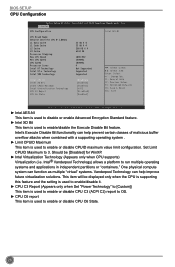
... Supported Supported Supported [Enabled] [Enabled] [Enabled] [All] [Disabled] [Enabled] → ←: Select Screen ↑ ↓: Select Item Enter: Select +/-: Change Opt. F1: General Help F2: Previous Values F3: Optimized Defaults F4: Save & Reset ESC: Exit Version 2.14.1219. This item will be [Disabled] for WinXP. ► Intel Virtualization Technology (Appears only when CPU supports) Virtualization (i.e. Should be displayed only when the CPU is supporting this feature and the setting is used to enable/disable it. ► CPU C3...
... Supported Supported Supported [Enabled] [Enabled] [Enabled] [All] [Disabled] [Enabled] → ←: Select Screen ↑ ↓: Select Item Enter: Select +/-: Change Opt. F1: General Help F2: Previous Values F3: Optimized Defaults F4: Save & Reset ESC: Exit Version 2.14.1219. This item will be [Disabled] for WinXP. ► Intel Virtualization Technology (Appears only when CPU supports) Virtualization (i.e. Should be displayed only when the CPU is supporting this feature and the setting is used to enable/disable it. ► CPU C3...
User manual
Page 34
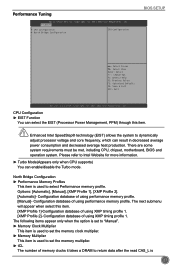
... is used to set the memory multiplier. ► tCL The number of memory clocks it takes a DRAM to return data after the read CAS_L is used to Intel Website for more information. ► Turbo Mode(Appears only when CPU supports) You can enable/disable the Turbo mode. F1: General Help F2: Previous Values F3: Optimized Defaults F4: Save & Exit ESC: Exit Version 2.14.1219. Options: [Automatic], [Manual...
... is used to set the memory multiplier. ► tCL The number of memory clocks it takes a DRAM to return data after the read CAS_L is used to Intel Website for more information. ► Turbo Mode(Appears only when CPU supports) You can enable/disable the Turbo mode. F1: General Help F2: Previous Values F3: Optimized Defaults F4: Save & Exit ESC: Exit Version 2.14.1219. Options: [Automatic], [Manual...

User manual
Page 37
...LAN PXE OpROM Onboard USB Controller Legacy USB Support USB3.0 Support Azalia HD Audio controller [Enabled] [Disabled] [Enabled] [Enabled] [Enabled] [Enabled] Onboard LAN Controller → ←: Select Screen ↑ ↓: Select Item Enter: Select +/-: Change Opt. Onboard Device Configuration Aptio Setup Utility - F1: General Help F2: Previous Values F3: Optimized Defaults F4: Save & Exit ESC: Exit Version 2.14.1219. If you have a USB keyboard or mouse, set to enable or disable the VT-d feature. BIOS SETUP ► UMA Frame buffer Size Allocates system memory for use...
...LAN PXE OpROM Onboard USB Controller Legacy USB Support USB3.0 Support Azalia HD Audio controller [Enabled] [Disabled] [Enabled] [Enabled] [Enabled] [Enabled] Onboard LAN Controller → ←: Select Screen ↑ ↓: Select Item Enter: Select +/-: Change Opt. Onboard Device Configuration Aptio Setup Utility - F1: General Help F2: Previous Values F3: Optimized Defaults F4: Save & Exit ESC: Exit Version 2.14.1219. If you have a USB keyboard or mouse, set to enable or disable the VT-d feature. BIOS SETUP ► UMA Frame buffer Size Allocates system memory for use...
User manual
Page 38
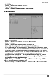
... all your SATA drives must also support AHCI. ► SATA Port1/SATA Port2/SATA Port3/SATA Port4 Press to go to its specification. When you can select IDE option to have a SATA device, which also supports AHCI, then you can select AHCI to get its best performance. [RAID] - ► USB3.0 Support This item is used to show the SATA Device information. 31 If your SATA ports. [Native IDE] - This item is used to support native IDE mode. [AHCI] - BIOS SETUP SATA Configuration Aptio Setup Utility -
... all your SATA drives must also support AHCI. ► SATA Port1/SATA Port2/SATA Port3/SATA Port4 Press to go to its specification. When you can select IDE option to have a SATA device, which also supports AHCI, then you can select AHCI to get its best performance. [RAID] - ► USB3.0 Support This item is used to show the SATA Device information. 31 If your SATA ports. [Native IDE] - This item is used to support native IDE mode. [AHCI] - BIOS SETUP SATA Configuration Aptio Setup Utility -

User manual
Page 40
... to install a TPM device on the motherboard and set this item to support TPM (Trusted Platform Module) device func- F1: General Help F2: Previous Values F3: Optimized Defaults F4: Save & Exit ESC: Exit Version 2.14.1219. O.S. Default option is used to decide whether to [Enabled], then save changing and reset your computer, otherwise the operation system can not show Security Device. Trusted Computing BIOS SETUP Aptio Setup Utility - TCG...
... to install a TPM device on the motherboard and set this item to support TPM (Trusted Platform Module) device func- F1: General Help F2: Previous Values F3: Optimized Defaults F4: Save & Exit ESC: Exit Version 2.14.1219. O.S. Default option is used to decide whether to [Enabled], then save changing and reset your computer, otherwise the operation system can not show Security Device. Trusted Computing BIOS SETUP Aptio Setup Utility - TCG...

User manual
Page 44
.... "Smart Fan Automatic Mode" is the principle figure of CPU is used to enable or disable smart fan function. This function works only when your operating system is supporting ACPI. ► CPU/System Smart Fan Function This option is used to set the warning temperature for your reference. F1: General Help F2: Previous Values F3: Optimized Defaults F4: Save & Exit ESC: Exit BIOS SETUP Version 2.02.1205. The CPU fan/ System speed are automatically detected and displayed...
.... "Smart Fan Automatic Mode" is the principle figure of CPU is used to enable or disable smart fan function. This function works only when your operating system is supporting ACPI. ► CPU/System Smart Fan Function This option is used to set the warning temperature for your reference. F1: General Help F2: Previous Values F3: Optimized Defaults F4: Save & Exit ESC: Exit BIOS SETUP Version 2.02.1205. The CPU fan/ System speed are automatically detected and displayed...
User manual
Page 45
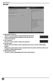
... to enter the CMOS setting program. ► HDD BootSector Write This item is used to 20 characters long. The password must be asked to enter a password when the system is started or when you enter the CMOS setting program. [Always]: You will be 1 to enable/disable boot sector write protection. 38 Administator Password HDD BOOTSector Write [Normal] → ←: Select Screen ↑ ↓: Select Item Enter: Select +/-: Change Opt. BIOS SETUP Security Aptio Setup Utility -
... to enter the CMOS setting program. ► HDD BootSector Write This item is used to 20 characters long. The password must be asked to enter a password when the system is started or when you enter the CMOS setting program. [Always]: You will be 1 to enable/disable boot sector write protection. 38 Administator Password HDD BOOTSector Write [Normal] → ←: Select Screen ↑ ↓: Select Item Enter: Select +/-: Change Opt. BIOS SETUP Security Aptio Setup Utility -
User manual
Page 48
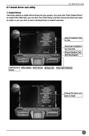
Install Driver Use these options to install it first. After that, you can click "One Click Setup" and then choose the items you want to install, or you want to install it manually. Manual Installation Step by Step Automatic Installation by One Click Drop to System Tray Exit the program Visit Foxconn's Show Utilities Show Drivers Browse CD View User's Manual website Choose the items you can click on each individual driver to install all the drivers for your system. You must click "Intel Chipset Driver" to Install 41 4-1 Install driver and utility CD INSTRUCTION 1.
Install Driver Use these options to install it first. After that, you can click "One Click Setup" and then choose the items you want to install, or you want to install it manually. Manual Installation Step by Step Automatic Installation by One Click Drop to System Tray Exit the program Visit Foxconn's Show Utilities Show Drivers Browse CD View User's Manual website Choose the items you can click on each individual driver to install all the drivers for your system. You must click "Intel Chipset Driver" to Install 41 4-1 Install driver and utility CD INSTRUCTION 1.
User manual
Page 73
..., it affects the entire array. This configuration provides optimal speed and reliability, but you need to set from 4KB to update the volume. If any RAID 1 drive fails, data access will not be set the strip size for speed RAID1 2 RAID5 >=3 RAID10 >=4 (Even number) Recovery 2 50% N-1 Smallest *2 Smaller Read faster Read faster Write slower High Read faster Excellent 100% Data backup Good...
..., it affects the entire array. This configuration provides optimal speed and reliability, but you need to set from 4KB to update the volume. If any RAID 1 drive fails, data access will not be set the strip size for speed RAID1 2 RAID5 >=3 RAID10 >=4 (Even number) Recovery 2 50% N-1 Smallest *2 Smaller Read faster Read faster Write slower High Read faster Excellent 100% Data backup Good...
User manual
Page 76
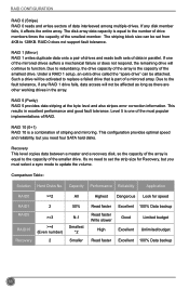
... main menu of RAID driver into the drive bays, connect all power and SATA cables. 5-5 BIOS Configuration 1. Enter the BIOS setup by pressing key during the POST(Power On Self Test). 2. Press the + to Chapter 3 BIOS Setup) 3. Create RAID Volume 4. Reset Disks to provide driver for additional specific devices, for example, a RAID device. 10. RAID CONFIGURATION 9. Enter RAID BIOS Setup When BIOS is restarted, it will reboot itself. 5-6 Create RAID in your computer. 10-2. Recover Volume Options 2. Check if the diskette contains the driver files. Install SATA hard disks...
... main menu of RAID driver into the drive bays, connect all power and SATA cables. 5-5 BIOS Configuration 1. Enter the BIOS setup by pressing key during the POST(Power On Self Test). 2. Press the + to Chapter 3 BIOS Setup) 3. Create RAID Volume 4. Reset Disks to provide driver for additional specific devices, for example, a RAID device. 10. RAID CONFIGURATION 9. Enter RAID BIOS Setup When BIOS is restarted, it will reboot itself. 5-6 Create RAID in your computer. 10-2. Recover Volume Options 2. Check if the diskette contains the driver files. Install SATA hard disks...
User manual
Page 99
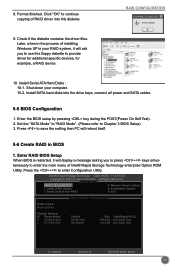
.... 4. RAID CONFIGURATION 4. Press key to the main menu. Intel(IRn)teMl(aRt)riRx aSptoidraSgteorMagaenaTgeecrhnoopltoiogny R -O UMpvti5o.n0.R0O.1M01-11I1C.H0.98R.12w0R4A I D 5 Copyright(C) 2003-1014 IInntteell CCoorrppoorraattiioonn. Recovery Volume Options 2. Reset Disks to On-Request. Exit RAID BIOS 1. A lAl lRl RigihgthstsRReseesrevrevde.d. [ MAIN MENU ] 1. The system will continue for Windows OS installation. Shut down the computer, remove the Non-RAID disk, and we will enter BIOS setup. 3. If you do not remove irrelevant hard disk, Windows...
.... 4. RAID CONFIGURATION 4. Press key to the main menu. Intel(IRn)teMl(aRt)riRx aSptoidraSgteorMagaenaTgeecrhnoopltoiogny R -O UMpvti5o.n0.R0O.1M01-11I1C.H0.98R.12w0R4A I D 5 Copyright(C) 2003-1014 IInntteell CCoorrppoorraattiioonn. Recovery Volume Options 2. Reset Disks to On-Request. Exit RAID BIOS 1. A lAl lRl RigihgthstsRReseesrevrevde.d. [ MAIN MENU ] 1. The system will continue for Windows OS installation. Shut down the computer, remove the Non-RAID disk, and we will enter BIOS setup. 3. If you do not remove irrelevant hard disk, Windows...
User manual
Page 101
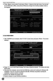
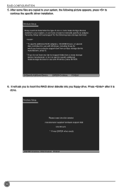
... manufacturer-supplied hardware support disk into you do not want to continue the specific driver installation. Currently, Setup will ask you to manually specify an adapter. Windows Setup Setup could not determine the type of one or more mass storage devices installed in your system, the following mass storage device(s): * To specify additional SCSI adapters, CD-ROM drivers, or special disk controllers for use with Windows, including those for use with Windows, press ENTER. It will load support...
... manufacturer-supplied hardware support disk into you do not want to continue the specific driver installation. Currently, Setup will ask you to manually specify an adapter. Windows Setup Setup could not determine the type of one or more mass storage devices installed in your system, the following mass storage device(s): * To specify additional SCSI adapters, CD-ROM drivers, or special disk controllers for use with Windows, including those for use with Windows, press ENTER. It will load support...


