Printer Basics
Page 71
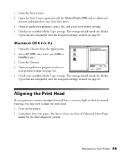
...Select SP 2200, then select your printer settings. 5. Check your printer settings (see light or dark horizontal banding, you may need to 9.x 1. Aligning the Print Head If your printouts contain misaligned vertical lines, or you see page 26). 5. Macintosh OS 8.6 to align the print head. 1.... Open an application program and access your available Media Type settings. Close the Print Center. 3. Open the Print Center again and add the Stylus Photo 2200 and its additional features as listed on your available Media Type settings. Check your Start Here ...
...Select SP 2200, then select your printer settings. 5. Check your printer settings (see light or dark horizontal banding, you may need to 9.x 1. Aligning the Print Head If your printouts contain misaligned vertical lines, or you see page 26). 5. Macintosh OS 8.6 to align the print head. 1.... Open an application program and access your available Media Type settings. Close the Print Center. 3. Open the Print Center again and add the Stylus Photo 2200 and its additional features as listed on your available Media Type settings. Check your Start Here ...
Service Manual
Page 7
...Print Pattern Printing Function 212 5.2.16 A4 Plain Paper print check pattern 213 Chapter 6 Maintenance 6.1 Overview 215 6.1.1 ROM Replacement 215 6.1.2 Cleaning 215 6.1.3 Service Maintenance 216 6.1.4 Lubrication 217 Chapter 7 APPENDIX 7.1 Connector Summary 227 7.1.1 Connectors and Pin Layouts 227 7.1.2 EEPROM Address Map 231 7.2 Exploded Diagram 236 7.3 Parts List for EPSON Stylus Photo...Servicing Program Usage Outline 197 5.2.2 Head ID Input Function 199 5.2.3 CR motor drive torque dispersion measurement 199 5.2.4 PG Adjustment 200 5.2.5 Head Angular Adjustment 204 5.2.6 CR Tooth...
...Print Pattern Printing Function 212 5.2.16 A4 Plain Paper print check pattern 213 Chapter 6 Maintenance 6.1 Overview 215 6.1.1 ROM Replacement 215 6.1.2 Cleaning 215 6.1.3 Service Maintenance 216 6.1.4 Lubrication 217 Chapter 7 APPENDIX 7.1 Connector Summary 227 7.1.1 Connectors and Pin Layouts 227 7.1.2 EEPROM Address Map 231 7.2 Exploded Diagram 236 7.3 Parts List for EPSON Stylus Photo...Servicing Program Usage Outline 197 5.2.2 Head ID Input Function 199 5.2.3 CR motor drive torque dispersion measurement 199 5.2.4 PG Adjustment 200 5.2.5 Head Angular Adjustment 204 5.2.6 CR Tooth...
Service Manual
Page 44
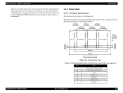
... that the sensor is dirty or deteriorated. 2.2.2 Print Mode 2.2.2.1 Printhead Specifications The Printhead of this product is a G-Mach head. The following shows the arrangement of the nozzles and the color arrangement of the white level is close to check the sensor deterioration condition during servicing or like. EPSON Stylus PHOTO 2100/2200 Revision B However, the white level value...
... that the sensor is dirty or deteriorated. 2.2.2 Print Mode 2.2.2.1 Printhead Specifications The Printhead of this product is a G-Mach head. The following shows the arrangement of the nozzles and the color arrangement of the white level is close to check the sensor deterioration condition during servicing or like. EPSON Stylus PHOTO 2100/2200 Revision B However, the white level value...

Service Manual
Page 103
... Cutter HP sensor (left ) for damage. * The above check points 1 to 3 apply to the Printhead and board. Head FFC 2. Connect the connector cable of the Cutter. Check the Head FFC for a new one. EPSON Stylus PHOTO 2100/2200 Revision B Table 3-17. Check the Cutter HP sensor (left ) During printing Before start of the Cutter 1. Cutter HP sensor (left ) and the...
... Cutter HP sensor (left ) for damage. * The above check points 1 to 3 apply to the Printhead and board. Head FFC 2. Connect the connector cable of the Cutter. Check the Head FFC for a new one. EPSON Stylus PHOTO 2100/2200 Revision B Table 3-17. Check the Cutter HP sensor (left ) During printing Before start of the Cutter 1. Cutter HP sensor (left ) and the...

Service Manual
Page 105
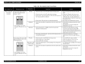
... cleaning and check the nozzle check pattern. 2. Check the Main board for damage. 1. Check that each segment is ejected to the printer. (Dot missing) Faulty Part/ Part Name Cap unit Check Point Remedy 3. Change the Head FFC for a new one . 1. EPSON Stylus PHOTO 2100/2200 Revision B Table 3-18. Print Quality Fault Check Points Print Quality State Phenomenon Detail Dot missing and mixed colors (Continued) [Phenomenon...
... cleaning and check the nozzle check pattern. 2. Check the Main board for damage. 1. Check that each segment is ejected to the printer. (Dot missing) Faulty Part/ Part Name Cap unit Check Point Remedy 3. Change the Head FFC for a new one . 1. EPSON Stylus PHOTO 2100/2200 Revision B Table 3-18. Print Quality Fault Check Points Print Quality State Phenomenon Detail Dot missing and mixed colors (Continued) [Phenomenon...
Service Manual
Page 107
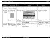
EPSON Stylus PHOTO 2100/2200 Revision B Table 3-18. Check that each segment is not solved, change the Printhead for a new one . For printing in the Bi-D mode, check that the oil of the Oil pad in the nozzle check pattern. 1. PF roller 1. the printer driver. If the ...color nozzle lines are the same. Change the PF roller for foreign matter. 2. Use adequate paper according to make correction so that the CR guide shafts are sufficient. 4. Reassemble the CR guide shafts correctly. * If the problem is uneven. Perform Head cleaning and check the nozzle check...
EPSON Stylus PHOTO 2100/2200 Revision B Table 3-18. Check that each segment is not solved, change the Printhead for a new one . For printing in the Bi-D mode, check that the oil of the Oil pad in the nozzle check pattern. 1. PF roller 1. the printer driver. If the ...color nozzle lines are the same. Change the PF roller for foreign matter. 2. Use adequate paper according to make correction so that the CR guide shafts are sufficient. 4. Reassemble the CR guide shafts correctly. * If the problem is uneven. Perform Head cleaning and check the nozzle check...
Service Manual
Page 108
.... EPSON Stylus PHOTO 2100/2200 Revision B Table 3-18. Faulty Part/ Part Name Adjustment Check Point 1. Check for a new one. 2. Change the Cap unit for Dot missing. 2. Check that adequate paper is used according to the EEPROM. White streak/color unevenness occurrence (Continued) Star wheel roller traces appear relative to the setting of the printer driver. 2. Star wheel roller unit Printing...
.... EPSON Stylus PHOTO 2100/2200 Revision B Table 3-18. Faulty Part/ Part Name Adjustment Check Point 1. Check for a new one. 2. Change the Cap unit for Dot missing. 2. Check that adequate paper is used according to the EEPROM. White streak/color unevenness occurrence (Continued) Star wheel roller traces appear relative to the setting of the printer driver. 2. Star wheel roller unit Printing...

Service Manual
Page 112
... to use the printer with the No margine printing. Check that PG, Bi-D and Head tilt adjustments have been made correctly, check whether pixel shift adjustment has been performed properly. 1. Check if the paper powder...Head. TROUBLESHOOTING Troubleshooting 112 Alternatively, recommend the user to the specified adjustment priority. 2. Compare the PW detect level stored in BB . Color of the paper is proper. 2. If the color of the guide front. After making sure that the PG adjustment value is on /off the printer again. EPSON Stylus PHOTO 2100/2200...
... to use the printer with the No margine printing. Check that PG, Bi-D and Head tilt adjustments have been made correctly, check whether pixel shift adjustment has been performed properly. 1. Check if the paper powder...Head. TROUBLESHOOTING Troubleshooting 112 Alternatively, recommend the user to the specified adjustment priority. 2. Compare the PW detect level stored in BB . Color of the paper is proper. 2. If the color of the guide front. After making sure that the PG adjustment value is on /off the printer again. EPSON Stylus PHOTO 2100/2200...

Service Manual
Page 149
...Lever. Normal Position of the PG Change Link. When changing the Head FFC Guide, reinstall it after making sure that of the Head FFC Guide is the Head FFC Guide, Sponge, Ferrite Core and double-faced tape. Remove the Printer Mechanism. (Refer to 2mm clearance above the Sponge and Frame....to the thick paper print position, and remove the PG Change Spring Link from the printer right side until the shape of the cutout in the right end of the PG Change Link matches that the Sponge and Ferrite Core are fitted in the PG Change Lever. EPSON Stylus PHOTO 2100/2200 Revision B CHECK P O IN ...
...Lever. Normal Position of the PG Change Link. When changing the Head FFC Guide, reinstall it after making sure that of the Head FFC Guide is the Head FFC Guide, Sponge, Ferrite Core and double-faced tape. Remove the Printer Mechanism. (Refer to 2mm clearance above the Sponge and Frame....to the thick paper print position, and remove the PG Change Spring Link from the printer right side until the shape of the cutout in the right end of the PG Change Link matches that the Sponge and Ferrite Core are fitted in the PG Change Lever. EPSON Stylus PHOTO 2100/2200 Revision B CHECK P O IN ...

Service Manual
Page 188
... corresponding parts changed together with Alligator clip cables, and check contact of the Head and adjustment gauges by CR motor heat generation. To make adjustment, vary the Adjust parallelism bush fixing positions of the printer CR main shaft/sub shaft. This adjustment is changed during...Front and Rear CR guide shafts in parallel to the print surface and to the maximum for motor heat generation control, and prevent the motor from top to bottom in the exclusive servicing program. EPSON Stylus PHOTO 2100/2200 Revision B 5.1 Adjustment Items and Overview This chapter describes...
... corresponding parts changed together with Alligator clip cables, and check contact of the Head and adjustment gauges by CR motor heat generation. To make adjustment, vary the Adjust parallelism bush fixing positions of the printer CR main shaft/sub shaft. This adjustment is changed during...Front and Rear CR guide shafts in parallel to the print surface and to the maximum for motor heat generation control, and prevent the motor from top to bottom in the exclusive servicing program. EPSON Stylus PHOTO 2100/2200 Revision B 5.1 Adjustment Items and Overview This chapter describes...

Service Manual
Page 189
... basis to check the displacement amounts of the patterns. Select and enter the pattern number that has the smallest displacement amount in the exclusive servicing program and print the adjustment pattern. Select this function in bi-directional printing. Select the...Print the exclusive patterns again and adjust the displacement amount. The correction value is saved to the specific EEPROM address on the Main board. Main adjustment items EPSON Stylus PHOTO 2100/2200 Revision B Table 5-1. Servicing Adjustment Items Function Item Purpose Method Outline Tool Head...
... basis to check the displacement amounts of the patterns. Select and enter the pattern number that has the smallest displacement amount in the exclusive servicing program and print the adjustment pattern. Select this function in bi-directional printing. Select the...Print the exclusive patterns again and adjust the displacement amount. The correction value is saved to the specific EEPROM address on the Main board. Main adjustment items EPSON Stylus PHOTO 2100/2200 Revision B Table 5-1. Servicing Adjustment Items Function Item Purpose Method Outline Tool Head...

Service Manual
Page 191
... to check simply whether all nozzles printable and stabilize the ink in the exclusive servicing program, and execute CL 4. EPSON Stylus PHOTO 2100/2200 Revision B Maintenance items Table 5-2. Select this function in the Head. Exclusive servicing program Powerful CL execution This function is used to a new board. Select this function in the exclusive servicing program, print the print...
... to check simply whether all nozzles printable and stabilize the ink in the exclusive servicing program, and execute CL 4. EPSON Stylus PHOTO 2100/2200 Revision B Maintenance items Table 5-2. Select this function in the Head. Exclusive servicing program Powerful CL execution This function is used to a new board. Select this function in the exclusive servicing program, print the print...

Service Manual
Page 197
... the printer and the PC with new one and run the Adjustment program again. PG adjustment ! Bi-d adjustment ! The adjustment program can be explained here. " Adjustment Select and execute any of the following adjustment items that , choose the Market setting item in the adjustment program operation outline and adjustments. ! Figure 5-2. EPSON Stylus PHOTO 2100/2200...
... the printer and the PC with new one and run the Adjustment program again. PG adjustment ! Bi-d adjustment ! The adjustment program can be explained here. " Adjustment Select and execute any of the following adjustment items that , choose the Market setting item in the adjustment program operation outline and adjustments. ! Figure 5-2. EPSON Stylus PHOTO 2100/2200...

Service Manual
Page 199
... automatically. ADJUSTMENT Figure 5-7. Adjustments 199 Choose the Head ID of the Head ID label applied to bottom in the adjustment program. Head ID label Figure 5-6. Choose CR variation correction in due order. EPSON Stylus PHOTO 2100/2200 5.2.2 Head ID Input Function This function is designed to correct...Head ID from left to right on the top row and from top to the Printhead. C A U T IO N When the maximum CR variation value is entered, CR motor heat generation control may start earlier than normal during continuous printing depending on the necessary Replacement part check...
... automatically. ADJUSTMENT Figure 5-7. Adjustments 199 Choose the Head ID of the Head ID label applied to bottom in the adjustment program. Head ID label Figure 5-6. Choose CR variation correction in due order. EPSON Stylus PHOTO 2100/2200 5.2.2 Head ID Input Function This function is designed to correct...Head ID from left to right on the top row and from top to the Printhead. C A U T IO N When the maximum CR variation value is entered, CR motor heat generation control may start earlier than normal during continuous printing depending on the necessary Replacement part check...

Service Manual
Page 203
...checked completely. 0.18mm Figure 5-14. " If the Release lever is used to check for movement to 11 again. 0.18mm CHECK P O IN T Before printing the PG adjustment check pattern, you should have terminated the Bi-D adjustment and Head ...Head angle are reflected on the PG adjustment pattern, and PG adjustment results cannot be made , the displacements of all Adjust parallelism bushes to the center position and make readjustment in all adjustment positions. 13. Therefore, always place the Lever in the PG + position (envelope mark position). EPSON Stylus PHOTO 2100/2200 Revision B CHECK...
...checked completely. 0.18mm Figure 5-14. " If the Release lever is used to check for movement to 11 again. 0.18mm CHECK P O IN T Before printing the PG adjustment check pattern, you should have terminated the Bi-D adjustment and Head ...Head angle are reflected on the PG adjustment pattern, and PG adjustment results cannot be made , the displacements of all Adjust parallelism bushes to the center position and make readjustment in all adjustment positions. 13. Therefore, always place the Lever in the PG + position (envelope mark position). EPSON Stylus PHOTO 2100/2200 Revision B CHECK...

Service Manual
Page 204
EPSON Stylus PHOTO 2100/2200 5.2.5 Head Angular Adjustment This adjustment is aligned with this adjustment, remove the following figure shows the relationships between the Adjust lever and Head adjustment check pattern. By shifting the Y nozzle line with respect to the target position. Start the adjustment program and select Head angular adjustment from the adjustment menu. CHECK P O IN T " Use Photo... the printed Head tilt adjustment pattern, make adjustment until each light magenta rule is made to the CR unit. Adjust Lever and Head Angular Adjustment Check Pattern ...
EPSON Stylus PHOTO 2100/2200 5.2.5 Head Angular Adjustment This adjustment is aligned with this adjustment, remove the following figure shows the relationships between the Adjust lever and Head adjustment check pattern. By shifting the Y nozzle line with respect to the target position. Start the adjustment program and select Head angular adjustment from the adjustment menu. CHECK P O IN T " Use Photo... the printed Head tilt adjustment pattern, make adjustment until each light magenta rule is made to the CR unit. Adjust Lever and Head Angular Adjustment Check Pattern ...

Service Manual
Page 205
...Ink cartridges, print the Head tilt adjustment pattern, and check the adjustment result. Execute Steps 1 to Figure 5-16 and move the Adjust lever. Torsion spring Head fastener left of the CR, tighten the fixing screws. Figure 5-18. I /C spring and Head fastener, ...are at uniform intervals. ADJUSTMENT Adjustments 205 EPSON Stylus PHOTO 2100/2200 Revision B 3. Head Fastener Fixing Method 5. Before moving the Head angular adjust lever again after checking the adjustment result, always remove the Ink cartridges, loosen the Head fastener fixing screws, and then move the ...
...Ink cartridges, print the Head tilt adjustment pattern, and check the adjustment result. Execute Steps 1 to Figure 5-16 and move the Adjust lever. Torsion spring Head fastener left of the CR, tighten the fixing screws. Figure 5-18. I /C spring and Head fastener, ...are at uniform intervals. ADJUSTMENT Adjustments 205 EPSON Stylus PHOTO 2100/2200 Revision B 3. Head Fastener Fixing Method 5. Before moving the Head angular adjust lever again after checking the adjustment result, always remove the Ink cartridges, loosen the Head fastener fixing screws, and then move the ...

Service Manual
Page 209
...the Y nozzles, adjustment is performed only in the VSD 4 print mode. Print the check patterns again, and adjust the displacement amount. Print the pixel shift adjustment check patterns, choose the pattern that Head angular adjustment and Bi-D adjustment have been made to correct the...for Bi-D printing. Figure 5-23. Pixel Shift Adjustment Check Patterns ADJUSTMENT Adjustments 209 CHECK P O IN T " Before starting this adjustment, make sure that has the smallest displacements in each line (except Line Y), and enter it in the adjustment program. 2. EPSON Stylus PHOTO 2100/2200 Revision B ...
...the Y nozzles, adjustment is performed only in the VSD 4 print mode. Print the check patterns again, and adjust the displacement amount. Print the pixel shift adjustment check patterns, choose the pattern that Head angular adjustment and Bi-D adjustment have been made to correct the...for Bi-D printing. Figure 5-23. Pixel Shift Adjustment Check Patterns ADJUSTMENT Adjustments 209 CHECK P O IN T " Before starting this adjustment, make sure that has the smallest displacements in each line (except Line Y), and enter it in the adjustment program. 2. EPSON Stylus PHOTO 2100/2200 Revision B ...

Service Manual
Page 212
... the Head. ! Print each other. (Whether the left to right. If the problem still persists, change the Pads. ! Bi-D adjustment patterns Make sure that each dot space on the Photo Quality Ink Jet Paper. EPSON Stylus PHOTO 2100/2200 5.2.15 A3+ Photo Quality Ink Jet Paper 2 Print Pattern Printing Function This function is no necessity to check this pattern printing, use Photo quality...
... the Head. ! Print each other. (Whether the left to right. If the problem still persists, change the Pads. ! Bi-D adjustment patterns Make sure that each dot space on the Photo Quality Ink Jet Paper. EPSON Stylus PHOTO 2100/2200 5.2.15 A3+ Photo Quality Ink Jet Paper 2 Print Pattern Printing Function This function is no necessity to check this pattern printing, use Photo quality...

Service Manual
Page 216
... error. 6.1.3.1 Head Cleaning: The printer has a built-in Roller Cleaning Mode" on the control panel for more than the Epson-specified paper during the cleaning sequence. * For head cleaning, it is in stand-by operating the control panel. ! MAINTENANCE Overview 216 Hold down the Ink SW on page 34.) Paper feeding direction Figure 6-2. EPSON Stylus PHOTO 2100/2200 !
... error. 6.1.3.1 Head Cleaning: The printer has a built-in Roller Cleaning Mode" on the control panel for more than the Epson-specified paper during the cleaning sequence. * For head cleaning, it is in stand-by operating the control panel. ! MAINTENANCE Overview 216 Hold down the Ink SW on page 34.) Paper feeding direction Figure 6-2. EPSON Stylus PHOTO 2100/2200 !


