
Service Manual
Page 37
Ink cartridge ! Free exclusive paper pack ! Roll paper auto cutter (Cutter, paper support basket, instruction manual): PMA3NRAC1 ! Instruction manual ! Sheet ! USB cable : USBCB2 PRODUCTION DESCRIPTION Casing Specifications 37 Roll paper holder ! Cleaning kit : 1 set : 1 set : 1 set : 1 set : 1 pc.... : T0343 : T0344 : T0345 : T0346 : T0347 : T0348 ! Ink cartridge storage box : PMICBOX1 ! CD-ROM (Printer driver utility) ! EPSON Stylus PHOTO 2100/2200 1.4 Casing Specifications EXTERNAL DIMENSIONS When tucked When used : 631 (width) × 320 (depth) × 205 mm (...
Ink cartridge ! Free exclusive paper pack ! Roll paper auto cutter (Cutter, paper support basket, instruction manual): PMA3NRAC1 ! Instruction manual ! Sheet ! USB cable : USBCB2 PRODUCTION DESCRIPTION Casing Specifications 37 Roll paper holder ! Cleaning kit : 1 set : 1 set : 1 set : 1 set : 1 pc.... : T0343 : T0344 : T0345 : T0346 : T0347 : T0348 ! Ink cartridge storage box : PMICBOX1 ! CD-ROM (Printer driver utility) ! EPSON Stylus PHOTO 2100/2200 1.4 Casing Specifications EXTERNAL DIMENSIONS When tucked When used : 631 (width) × 320 (depth) × 205 mm (...
Service Manual
Page 79
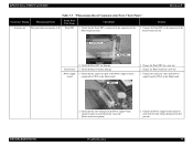
...correctly. Blue line 2. Change the Panel FFC for a new one . 1. Connect the Power supply board connector cable with the blue-lined side placed on The printer does not operate at all. Troubleshooting 79 Check the Panel FFC for damage. Remedy 1. Check the Panel board ...the connector of the Power supply board to CN15 on the Main board. Faulty Part/ Part Name Panel FFC Check Point 1. EPSON Stylus PHOTO 2100/2200 Revision B Table 3-3. "Phenomenon-Based Communication Error Check Points" Occurrence Timing Phenomenon Detail At power-on the 1 pin side. Power ...
...correctly. Blue line 2. Change the Panel FFC for a new one . 1. Connect the Power supply board connector cable with the blue-lined side placed on The printer does not operate at all. Troubleshooting 79 Check the Panel FFC for damage. Remedy 1. Check the Panel board ...the connector of the Power supply board to CN15 on the Main board. Faulty Part/ Part Name Panel FFC Check Point 1. EPSON Stylus PHOTO 2100/2200 Revision B Table 3-3. "Phenomenon-Based Communication Error Check Points" Occurrence Timing Phenomenon Detail At power-on the 1 pin side. Power ...
Service Manual
Page 80
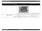
... PC and printer. 2. Check the Interface cable for damage. 5. Check that the Fuse (F1) on is normal, but the error appears when the print jog is not blown. 3. Install the EPSON USB driver. TROUBLESHOOTING Troubleshooting 80 EPSON USB 1. EPSON Stylus PHOTO 2100/2200 Revision B ...Table 3-3. Fuse (F1) At operation Connector cable Operation at all. driver installed in the PC. Faulty Part/ Part Name...
... PC and printer. 2. Check the Interface cable for damage. 5. Check that the Fuse (F1) on is normal, but the error appears when the print jog is not blown. 3. Install the EPSON USB driver. TROUBLESHOOTING Troubleshooting 80 EPSON USB 1. EPSON Stylus PHOTO 2100/2200 Revision B ...Table 3-3. Fuse (F1) At operation Connector cable Operation at all. driver installed in the PC. Faulty Part/ Part Name...
Service Manual
Page 82
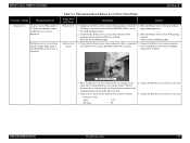
...board (CN1) securely. Move the Release lever to the Release lever sensor and Main board (CN1) securely. cable to the CD-R printing position. (Only for Stylus PHOTO 2100) 2. Release lever sensor 2. TROUBLESHOOTING Troubleshooting 82 Connect the Release lever sensor connector to the original position ...CD-R tray is normal. • Connector (CN1) Open Not open and Release lever error is displayed. EPSON Stylus PHOTO 2100/2200 Revision B Occurrence Timing Phenomenon Detail At power-on At power-on, the Paper guide of the Printer mechanism is open : 3.3V : 0V 2.
...board (CN1) securely. Move the Release lever to the Release lever sensor and Main board (CN1) securely. cable to the CD-R printing position. (Only for Stylus PHOTO 2100) 2. Release lever sensor 2. TROUBLESHOOTING Troubleshooting 82 Connect the Release lever sensor connector to the original position ...CD-R tray is normal. • Connector (CN1) Open Not open and Release lever error is displayed. EPSON Stylus PHOTO 2100/2200 Revision B Occurrence Timing Phenomenon Detail At power-on At power-on, the Paper guide of the Printer mechanism is open : 3.3V : 0V 2.
Service Manual
Page 84
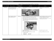
... the PE sensor is not fed. Remedy 1. Check that the Sensor base is connected securely to the above photo.) 4. Check that the PE sensor connector cable is mounted to the Frame securely. (Refer to 1. Torsion spring Detection lever Sensor base 3. Install the Sensor... PE sensor ASF sensor wheel LD rollers 1. TROUBLESHOOTING Troubleshooting 84 Connect the PE sensor connector cable to feed paper but stops at the PE sensor lever. EPSON Stylus PHOTO 2100/2200 Revision B Occurrence Timing Phenomenon Detail At operation After start of printing operation, the LD rollers ...
... the PE sensor is not fed. Remedy 1. Check that the Sensor base is connected securely to the above photo.) 4. Check that the PE sensor connector cable is mounted to the Frame securely. (Refer to 1. Torsion spring Detection lever Sensor base 3. Install the Sensor... PE sensor ASF sensor wheel LD rollers 1. TROUBLESHOOTING Troubleshooting 84 Connect the PE sensor connector cable to feed paper but stops at the PE sensor lever. EPSON Stylus PHOTO 2100/2200 Revision B Occurrence Timing Phenomenon Detail At operation After start of printing operation, the LD rollers ...

Service Manual
Page 93
...Remove the paper dust, foreign matter, etc. Check that the connector cable of the Cutter CN2 on the Driver board securely. Change the Cutter unit for damage. 3. Use the EPSON special media. 2. TROUBLESHOOTING Troubleshooting 93 motor to 1. At roll paper ... failure. 2. Connect the connector cable of the Cutter motor is not other than the EPSON special media. 2. Check the Cutter for a new one . 1. Change the Cutter motor for damage. 1. Check the rail groove of the Cutter. 1. EPSON Stylus PHOTO 2100/2200 Revision B Occurrence Timing Phenomenon Detail...
...Remove the paper dust, foreign matter, etc. Check that the connector cable of the Cutter CN2 on the Driver board securely. Change the Cutter unit for damage. 3. Use the EPSON special media. 2. TROUBLESHOOTING Troubleshooting 93 motor to 1. At roll paper ... failure. 2. Connect the connector cable of the Cutter motor is not other than the EPSON special media. 2. Check the Cutter for a new one . 1. Change the Cutter motor for damage. 1. Check the rail groove of the Cutter. 1. EPSON Stylus PHOTO 2100/2200 Revision B Occurrence Timing Phenomenon Detail...

Service Manual
Page 94
... Check that the Cutter is connected to CN2 1. Change the Cutter motor for paper dust, foreign matter, etc. Check the Cutter motor connector cable for a new one . 1. At roll paper feeding After the roll paper is connected securely. 3. Check the Cutter HP sensor (right) ... to CN4 on the Driver board securely. 3. Connect the connector cable of the by auto loading Cutter produces operating noise. (right) Cutter for a new one. 3. Table 3-15. the Driver board securely. EPSON Stylus PHOTO 2100/2200 Revision B Occurrence Timing Phenomenon Detail At Cutter unit fitting (At ...
... Check that the Cutter is connected to CN2 1. Change the Cutter motor for paper dust, foreign matter, etc. Check the Cutter motor connector cable for a new one . 1. At roll paper feeding After the roll paper is connected securely. 3. Check the Cutter HP sensor (right) ... to CN4 on the Driver board securely. 3. Connect the connector cable of the by auto loading Cutter produces operating noise. (right) Cutter for a new one. 3. Table 3-15. the Driver board securely. EPSON Stylus PHOTO 2100/2200 Revision B Occurrence Timing Phenomenon Detail At Cutter unit fitting (At ...

Service Manual
Page 96
...Main board correctly. Check 6C and 6D of the CR motor is connected to CN17 1. TROUBLESHOOTING Troubleshooting 96 CR motor 1. Check the CR motor connector cable for a new one. 3. Change the CR motor for a new one . CR drive system 1. Oil pad Carriage unit bottom Carriage shaft B ... the CR motor for a new one . Check that the resistance of the EEPROM to on sequence is executed but Fatal error is overloaded. EPSON Stylus PHOTO 2100/2200 Revision B Table 3-17. Using a tester, check that the oil of the Oil pad in Check point 2, change the CR motor for ...
...Main board correctly. Check 6C and 6D of the CR motor is connected to CN17 1. TROUBLESHOOTING Troubleshooting 96 CR motor 1. Check the CR motor connector cable for a new one. 3. Change the CR motor for a new one . CR drive system 1. Oil pad Carriage unit bottom Carriage shaft B ... the CR motor for a new one . Check that the resistance of the EEPROM to on sequence is executed but Fatal error is overloaded. EPSON Stylus PHOTO 2100/2200 Revision B Table 3-17. Using a tester, check that the oil of the Oil pad in Check point 2, change the CR motor for ...

Service Manual
Page 97
EPSON Stylus PHOTO 2100/2200 Revision B Table 3-17. If the value is connected to CN16 1. Connect the PF motor connector cable to confirm that the PF motor connector cable is as in Check point 2, change the PF motor for damage. 2. Change the PF motor for a new one. Check B9 of the PF motor is ... is executed but Fatal error is abnormal, change the PF motor for a new one . 3. CN16 on the Main board correctly. Check the PF motor connector cable for a new one . If the resistance value is displayed.
EPSON Stylus PHOTO 2100/2200 Revision B Table 3-17. If the value is connected to CN16 1. Connect the PF motor connector cable to confirm that the PF motor connector cable is as in Check point 2, change the PF motor for damage. 2. Change the PF motor for a new one. Check B9 of the PF motor is ... is executed but Fatal error is abnormal, change the PF motor for a new one . 3. CN16 on the Main board correctly. Check the PF motor connector cable for a new one . If the resistance value is displayed.

Service Manual
Page 98
... damage. 2. TROUBLESHOOTING Troubleshooting 98 Check that the ASF motor connector cable is mounted between the DE lock lever and DE unit. Extension spring 0.618 DE lock lever 2. CN8 on , the ASF unit does not operate at ... Fatal Error Check Points Occurrence Timing Phenomenon Detail Faulty Part/Part Name Check Point Remedy At power-on At power-on the Main board correctly. EPSON Stylus PHOTO 2100/2200 Revision B Table 3-17. At power-on the Main board correctly.
... damage. 2. TROUBLESHOOTING Troubleshooting 98 Check that the ASF motor connector cable is mounted between the DE lock lever and DE unit. Extension spring 0.618 DE lock lever 2. CN8 on , the ASF unit does not operate at ... Fatal Error Check Points Occurrence Timing Phenomenon Detail Faulty Part/Part Name Check Point Remedy At power-on At power-on the Main board correctly. EPSON Stylus PHOTO 2100/2200 Revision B Table 3-17. At power-on the Main board correctly.

Service Manual
Page 101
... scale (Linear encoder) for damage, and turn the ASF sensor wheel manually and check that the ASF sensor connector cable is connected to the Sensor and Main board securely. ASF sensor connector cable ASF sensor 2. Check the ASF sensor for a new one . If the voltage value is as indicated below with the... hopper produces operating noise. At power-on the Main board is abnormal, change the ASF sensor for damage or contamination. Connect the ASF sensor connector cable to the Sensor and Main board securely. EPSON Stylus PHOTO 2100/2200 Revision B Table 3-17. ASF sensor 1.
... scale (Linear encoder) for damage, and turn the ASF sensor wheel manually and check that the ASF sensor connector cable is connected to the Sensor and Main board securely. ASF sensor connector cable ASF sensor 2. Check the ASF sensor for a new one . If the voltage value is as indicated below with the... hopper produces operating noise. At power-on the Main board is abnormal, change the ASF sensor for damage or contamination. Connect the ASF sensor connector cable to the Sensor and Main board securely. EPSON Stylus PHOTO 2100/2200 Revision B Table 3-17. ASF sensor 1.

Service Manual
Page 103
from most nozzles. Check for damage. 1. groove of the Cutter 1. Connect the connector cable of the Cutter HP sensor (left ) to the Printhead and Main 1. Check that the connector cable of the Cutter HP sensor (left ) is connected to CN3 on In Cutter initialization operation... the Head FFC for damage. * The above check points 1 to 3 apply to the Printhead and board. TROUBLESHOOTING Troubleshooting 103 EPSON Stylus PHOTO 2100/2200 Revision B Table 3-17. Ink is then started. Check the Head FFC for occurrence of printing, initial filling is executed and ...
from most nozzles. Check for damage. 1. groove of the Cutter 1. Connect the connector cable of the Cutter HP sensor (left ) to the Printhead and Main 1. Check that the connector cable of the Cutter HP sensor (left ) is connected to CN3 on In Cutter initialization operation... the Head FFC for damage. * The above check points 1 to 3 apply to the Printhead and board. TROUBLESHOOTING Troubleshooting 103 EPSON Stylus PHOTO 2100/2200 Revision B Table 3-17. Ink is then started. Check the Head FFC for occurrence of printing, initial filling is executed and ...

Service Manual
Page 116
...debranche. " If ink has adhered to do your work. When you cannot disconnect the power cable for disassembly and reassembly. DISASSEMBLY AND ASSEMBLY Overview 116 EPSON Stylus PHOTO 2100/2200 Revision B 4.1 Overview This chapter describes procedures for disassembling and assembling this chapter, refer to ...heading "WARNING". • Caution Precautions for any units or parts that could result in this product, always disconnect the power cable. " To protect the microprocessors and circuitry, use static discharge equipment, such as anti-static wrist straps, and handle them...
...debranche. " If ink has adhered to do your work. When you cannot disconnect the power cable for disassembly and reassembly. DISASSEMBLY AND ASSEMBLY Overview 116 EPSON Stylus PHOTO 2100/2200 Revision B 4.1 Overview This chapter describes procedures for disassembling and assembling this chapter, refer to ...heading "WARNING". • Caution Precautions for any units or parts that could result in this product, always disconnect the power cable. " To protect the microprocessors and circuitry, use static discharge equipment, such as anti-static wrist straps, and handle them...

Service Manual
Page 126
EPSON Stylus PHOTO 2100/2200 Revision B C A U T IO N Fully be careful when removing the Printer Mechanism after peeling the Waste Ink Pad from the Lower Housing. Refer to Figure 4-11, "Screws That Secure the Printer Mechanism" and Figure 4-48, "Removing the Extension Springs 1.554". 5. PF ...with double-faced tape. Disconnecting the Cutter Connector Cables When reinstalling the Printer Mechanism, route the Cutter Connector Cables in the groove A shown in the following adjustments are not caught between the Printer Mechanism and Lower Housing. Perform the adjustments in ...
EPSON Stylus PHOTO 2100/2200 Revision B C A U T IO N Fully be careful when removing the Printer Mechanism after peeling the Waste Ink Pad from the Lower Housing. Refer to Figure 4-11, "Screws That Secure the Printer Mechanism" and Figure 4-48, "Removing the Extension Springs 1.554". 5. PF ...with double-faced tape. Disconnecting the Cutter Connector Cables When reinstalling the Printer Mechanism, route the Cutter Connector Cables in the groove A shown in the following adjustments are not caught between the Printer Mechanism and Lower Housing. Perform the adjustments in ...

Service Manual
Page 128
...DISASSEMBLY AND ASSEMBLY Disassembly 128 EPSON Stylus PHOTO 2100/2200 3. Revision B " Connect the Connector Cables to the Connectors that secure the Ferrite Cores to the Board Unit. Disconnect the Connector Cables and FFCs from the Main Board, and pull and remove the Board Unit from the Printer Mechanism again to Figure 4-15...bundle the Connector Cables and FFCs (narrow FFCs) with the Tie Wrap Bands and Ferrite Cores. Disengage the two Tie Wrap Bands and the hooks of Harnesses and FFCs " When reinstalling the Board Unit, fit the screws in the order shown in colors and pin counts...
...DISASSEMBLY AND ASSEMBLY Disassembly 128 EPSON Stylus PHOTO 2100/2200 3. Revision B " Connect the Connector Cables to the Connectors that secure the Ferrite Cores to the Board Unit. Disconnect the Connector Cables and FFCs from the Main Board, and pull and remove the Board Unit from the Printer Mechanism again to Figure 4-15...bundle the Connector Cables and FFCs (narrow FFCs) with the Tie Wrap Bands and Ferrite Cores. Disengage the two Tie Wrap Bands and the hooks of Harnesses and FFCs " When reinstalling the Board Unit, fit the screws in the order shown in colors and pin counts...

Service Manual
Page 129
... Board 1 3 C.B.S 3×6 C.P 3×6 2 5 4 Figure 4-18. Blue line 1 2 1 pin side 1 CN15 3. When reconnecting the cable, insert the pins correctly into the corresponding ports of the Main Board. Remove the Board Unit. (Refer to Figure 4-17, "Connector...drawn on the Connector Cable, to Figure 4-17, "Connector Cable Lock Mechanism". Screws That Secure the Main Board Fit the screws 6) C.B.S 3×6 in the order shown in Figure 4-18. Connector Cable Lock Mechanism DISASSEMBLY AND ASSEMBLY Disassembly 129 EPSON Stylus PHOTO 2100/2200 Revision B 4.2.2.3 Removing...
... Board 1 3 C.B.S 3×6 C.P 3×6 2 5 4 Figure 4-18. Blue line 1 2 1 pin side 1 CN15 3. When reconnecting the cable, insert the pins correctly into the corresponding ports of the Main Board. Remove the Board Unit. (Refer to Figure 4-17, "Connector...drawn on the Connector Cable, to Figure 4-17, "Connector Cable Lock Mechanism". Screws That Secure the Main Board Fit the screws 6) C.B.S 3×6 in the order shown in Figure 4-18. Connector Cable Lock Mechanism DISASSEMBLY AND ASSEMBLY Disassembly 129 EPSON Stylus PHOTO 2100/2200 Revision B 4.2.2.3 Removing...

Service Manual
Page 130
... of the Main Board. (Refer to be read from the old Board, adjustments and Waste Ink Pad changing are necessary. Fitting the Protective Sheet 130 EPSON Stylus PHOTO 2100/2200 A D JU S TM E N T R E Q U IR E D " When changing the Main Board, the following order. Parts to Steps 1 and 2 in 4.2.2.3.) 2. USB ID input 4. PW sensor ... Board, and remove the PSB/PSE Board from CN15 of the Board Unit. EEPROM initialization 3. IEEE-1394 ID input 5. Disconnect the Connector Cable from the Board Unit. 1 4 PSB/PSE Board C.B.S 3×6 C.B.P 3×6 2 3 Figure 4-19.
... of the Main Board. (Refer to be read from the old Board, adjustments and Waste Ink Pad changing are necessary. Fitting the Protective Sheet 130 EPSON Stylus PHOTO 2100/2200 A D JU S TM E N T R E Q U IR E D " When changing the Main Board, the following order. Parts to Steps 1 and 2 in 4.2.2.3.) 2. USB ID input 4. PW sensor ... Board, and remove the PSB/PSE Board from CN15 of the Board Unit. EEPROM initialization 3. IEEE-1394 ID input 5. Disconnect the Connector Cable from the Board Unit. 1 4 PSB/PSE Board C.B.S 3×6 C.B.P 3×6 2 3 Figure 4-19.

Service Manual
Page 132
When reapplying them if their adhesive force is weak. Ink Tube Revision B 4.2.4 Removing the ASF Unit 1. Disconnect the Connector Cable of the Ink Tube". Specified Position of the Waste Ink Pads. Screws That Secure the Roll Paper Guide 4. While lifting the Roll ...Paper Guide and ASF Unit slightly upward as viewed from the printer front are fixed by double-faced tape. Hooks That Secure the Roll Paper Guide DISASSEMBLY AND ASSEMBLY Disassembly 132 EPSON Stylus PHOTO 2100/2200 " The Waste Ink Pads (Small) and the Waste Ink Pads located on the ...
When reapplying them if their adhesive force is weak. Ink Tube Revision B 4.2.4 Removing the ASF Unit 1. Disconnect the Connector Cable of the Ink Tube". Specified Position of the Waste Ink Pads. Screws That Secure the Roll Paper Guide 4. While lifting the Roll ...Paper Guide and ASF Unit slightly upward as viewed from the printer front are fixed by double-faced tape. Hooks That Secure the Roll Paper Guide DISASSEMBLY AND ASSEMBLY Disassembly 132 EPSON Stylus PHOTO 2100/2200 " The Waste Ink Pads (Small) and the Waste Ink Pads located on the ...

Service Manual
Page 142
... Eject Unit 1 DISASSEMBLY AND ASSEMBLY Disassembly 142 Refer to above the notches of the left and right hooks of the CD-R Sensor, release the Connector Cable from the center, and raise the left and right engagement portions and the right center side hook. 3 2 3 2 1 1 Engagement portion Hook...4-46, "Screws That Secure the Front Frame". Pull the Front Frame from the Printer Mechanism to the front as viewed from the printer front, slightly lift the front side to release the right-hand side hook from the two Tie Wraps, and remove the Front Frame. EPSON Stylus PHOTO 2100/2200 7.
... Eject Unit 1 DISASSEMBLY AND ASSEMBLY Disassembly 142 Refer to above the notches of the left and right hooks of the CD-R Sensor, release the Connector Cable from the center, and raise the left and right engagement portions and the right center side hook. 3 2 3 2 1 1 Engagement portion Hook...4-46, "Screws That Secure the Front Frame". Pull the Front Frame from the Printer Mechanism to the front as viewed from the printer front, slightly lift the front side to release the right-hand side hook from the two Tie Wraps, and remove the Front Frame. EPSON Stylus PHOTO 2100/2200 7.

Service Manual
Page 143
EPSON Stylus PHOTO 2100/2200 12. " Make sure that the two Extension Springs 1.554 are fitted properly. Printer front Paper Eject Unit Normal position of left side of the Carriage Guide Shaft B as seen from the printer front is installed properly since it from the printer front, and then ... the Paper Eject Unit, make sure that the U-cut portion Figure 4-51. Normal Positions of Paper Eject Unit Engagement Portions " Connect the Connector Cable of the Paper Eject Unit. Revision B C A U T IO N " Make sure that the engagement portions with the Tie Wraps in the correct...
EPSON Stylus PHOTO 2100/2200 12. " Make sure that the two Extension Springs 1.554 are fitted properly. Printer front Paper Eject Unit Normal position of left side of the Carriage Guide Shaft B as seen from the printer front is installed properly since it from the printer front, and then ... the Paper Eject Unit, make sure that the U-cut portion Figure 4-51. Normal Positions of Paper Eject Unit Engagement Portions " Connect the Connector Cable of the Paper Eject Unit. Revision B C A U T IO N " Make sure that the engagement portions with the Tie Wraps in the correct...


