Service Manual
Page 7
4.2.6 Removing the Paper Eject Roller B 144 4.2.7 Removing the Printhead 146 4.2.8 Removing the Carriage Guide Shaft B 149 4.2.9 Removing the Carriage Guide Shaft A ...210 5.2.13 IEEE-1394 ID Input 211 5.2.14 First dot position adjsutment (Left/Right Margin Adjustment 211 5.2.15 ..... A3+ Photo Quality Ink Jet Paper 2 Print Pattern Printing Function 212 5.2.16 A4 Plain Paper print check pattern 213 Chapter 6 Maintenance 6.1 ... 7.1.1 Connectors and Pin Layouts 227 7.1.2 EEPROM Address Map 231 7.2 Exploded Diagram 236 7.3 Parts List for EPSON Stylus Photo 2100 248 7.4 Circuit Diagram 253
4.2.6 Removing the Paper Eject Roller B 144 4.2.7 Removing the Printhead 146 4.2.8 Removing the Carriage Guide Shaft B 149 4.2.9 Removing the Carriage Guide Shaft A ...210 5.2.13 IEEE-1394 ID Input 211 5.2.14 First dot position adjsutment (Left/Right Margin Adjustment 211 5.2.15 ..... A3+ Photo Quality Ink Jet Paper 2 Print Pattern Printing Function 212 5.2.16 A4 Plain Paper print check pattern 213 Chapter 6 Maintenance 6.1 ... 7.1.1 Connectors and Pin Layouts 227 7.1.2 EEPROM Address Map 231 7.2 Exploded Diagram 236 7.3 Parts List for EPSON Stylus Photo 2100 248 7.4 Circuit Diagram 253
Service Manual
Page 40
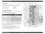
... roller A Paper eject roller B PW sensor ASF sensor wheel LD roller shaft Printhead CR unit CD-R sensor CR shaft B CR encoder sensor LD roller PE sensor... circuit board : C387 PSB/PSE ! The following shows the outline of this product. EPSON Stylus PHOTO 2100/2200 Revision B 2.1 Overview This chapter explains the operating principles of the mechanical sections and electrical... guide is provided. Control panel board : C387 PNL 2.2 Printer Mechanism Like the Stylus PHOTO 2000P, this motor does not require a scale, photo sensor and like to be fitted to drive the Paper loading...
... roller A Paper eject roller B PW sensor ASF sensor wheel LD roller shaft Printhead CR unit CD-R sensor CR shaft B CR encoder sensor LD roller PE sensor... circuit board : C387 PSB/PSE ! The following shows the outline of this product. EPSON Stylus PHOTO 2100/2200 Revision B 2.1 Overview This chapter explains the operating principles of the mechanical sections and electrical... guide is provided. Control panel board : C387 PNL 2.2 Printer Mechanism Like the Stylus PHOTO 2000P, this motor does not require a scale, photo sensor and like to be fitted to drive the Paper loading...
Service Manual
Page 44
... arrangement of the nozzles and the color arrangement of this product is not used to that of the PW detection level, it means that the sensor is dirty or deteriorated. 2.2.2 Print Mode 2.2.2.1 Printhead Specifications The Printhead of each nozzle line when they ...EPSON Stylus PHOTO 2100/2200 Revision B However, the white level value is a G-Mach head. Nozzle Rear View Table 2-3. Relationships between Nozzle Lines and Color Arrangement Line Ink A Photo-black or Matte-black B Light-black or Matte-black C Cyan D Light cyan E Magenta F Light magenta G Yellow Printer...
... arrangement of the nozzles and the color arrangement of this product is not used to that of the PW detection level, it means that the sensor is dirty or deteriorated. 2.2.2 Print Mode 2.2.2.1 Printhead Specifications The Printhead of each nozzle line when they ...EPSON Stylus PHOTO 2100/2200 Revision B However, the white level value is a G-Mach head. Nozzle Rear View Table 2-3. Relationships between Nozzle Lines and Color Arrangement Line Ink A Photo-black or Matte-black B Light-black or Matte-black C Cyan D Light cyan E Magenta F Light magenta G Yellow Printer...

Service Manual
Page 55
...Position : Placed about 1/4 lower to reduce the traces of the Knurled rollers. EPSON Stylus PHOTO 2100/2200 Revision B The paper fed from the ASF, Roll paper guide or Board paper ...Printer Mechanism 55 As compared to hold down transferred paper during printing. To eliminate the deflection of the paper, the paper is then returned toward the front of the Upper frame, and its main function is to the Stylus PHOTO... 2000P, the rubber roller on the right side of the Paper guide. Paper eject support roller Printhead Paper Star wheel roller Driven...
...Position : Placed about 1/4 lower to reduce the traces of the Knurled rollers. EPSON Stylus PHOTO 2100/2200 Revision B The paper fed from the ASF, Roll paper guide or Board paper ...Printer Mechanism 55 As compared to hold down transferred paper during printing. To eliminate the deflection of the paper, the paper is then returned toward the front of the Upper frame, and its main function is to the Stylus PHOTO... 2000P, the rubber roller on the right side of the Paper guide. Paper eject support roller Printhead Paper Star wheel roller Driven...

Service Manual
Page 56
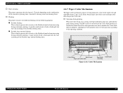
...time Photo-ink (HCD ink: Photo-black, Light-black) is easy to dry, but Matte-ink (PPI ink: Matte-black) is difficult to paper loading amount conditions. When the paper loading instruction is less than 2672/1440 steps, the time taken between the sensors and paper modes. Paper Roller Printhead Wait... the Paper feed switch causes the PW sensor to detect the leading edge of the paper and the printer to perform paper locating control and enter the standby status. EPSON Stylus PHOTO 2100/2200 2.2.4.3 Paper Mode Setting The paper mode that the time to reach the roller will be the wait ...
...time Photo-ink (HCD ink: Photo-black, Light-black) is easy to dry, but Matte-ink (PPI ink: Matte-black) is difficult to paper loading amount conditions. When the paper loading instruction is less than 2672/1440 steps, the time taken between the sensors and paper modes. Paper Roller Printhead Wait... the Paper feed switch causes the PW sensor to detect the leading edge of the paper and the printer to perform paper locating control and enter the standby status. EPSON Stylus PHOTO 2100/2200 2.2.4.3 Paper Mode Setting The paper mode that the time to reach the roller will be the wait ...
Service Manual
Page 58
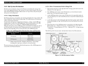
... moves toward the Combination gear 17.19, 25.6. 4. Table 2-14. DE Mechanism Outline OPERATING PRINCIPLES Printer Mechanism 58 Motor pinion gear → Planetary lever unit → Combination gear 17.19, 25.6...the Planetary lever unit in position. 5. As the CR unit moves leftward from the Printhead or Cap assembly. To provide the driving force of the DE mechanism. The following shows...and Capping mechanism. The Cap unit is in head cleaning wiper. EPSON Stylus PHOTO 2100/2200 Revision B 2.2.5 Ink System Mechanism The Ink system mechanism consists of the ASF/ Pump motor, ...
... moves toward the Combination gear 17.19, 25.6. 4. Table 2-14. DE Mechanism Outline OPERATING PRINCIPLES Printer Mechanism 58 Motor pinion gear → Planetary lever unit → Combination gear 17.19, 25.6...the Planetary lever unit in position. 5. As the CR unit moves leftward from the Printhead or Cap assembly. To provide the driving force of the DE mechanism. The following shows...and Capping mechanism. The Cap unit is in head cleaning wiper. EPSON Stylus PHOTO 2100/2200 Revision B 2.2.5 Ink System Mechanism The Ink system mechanism consists of the ASF/ Pump motor, ...

Service Manual
Page 59
...Operating Principle Printhead Cap Ink tube Figure 2-15. Capping Mechanism Slider cap rises to suck ink from the Cap unit toward the Waste ink pad. 2. Cap unit side 2.2.5.3 Capping Mechanism The Capping mechanism uses the driving force of capping operation. OPERATING PRINCIPLES Printer Mechanism ...EPSON Stylus PHOTO 2100/2200 Revision B The following diagram shows the outline of the Pump unit to come into close contact with the Head surface to secure moisture retention in the Cap, preventing the Head from being clogged with the Head surface to perform capping. When the printer ...
...Operating Principle Printhead Cap Ink tube Figure 2-15. Capping Mechanism Slider cap rises to suck ink from the Cap unit toward the Waste ink pad. 2. Cap unit side 2.2.5.3 Capping Mechanism The Capping mechanism uses the driving force of capping operation. OPERATING PRINCIPLES Printer Mechanism ...EPSON Stylus PHOTO 2100/2200 Revision B The following diagram shows the outline of the Pump unit to come into close contact with the Head surface to secure moisture retention in the Cap, preventing the Head from being clogged with the Head surface to perform capping. When the printer ...
Service Manual
Page 63
... ! A specific small amount of ink is discharged into the Cap according to 1.27g/color depending on both ends of the cutter operation area, detect whether the Cutter blade operates...in all), Relay board, Paper eject roller shaft and Paper holddown flap in the Printhead nozzles from increasing during continuous printing. Right HP sensor Left HP sensor Cutter motor .... ! Cutter Mechanism OPERATING PRINCIPLES Printer Mechanism 63 Timer cleaning This printer consumes the ink of such main parts as the Cutter motor, left and right HP sensors (2 pcs. EPSON Stylus PHOTO 2100/2200 !
... ! A specific small amount of ink is discharged into the Cap according to 1.27g/color depending on both ends of the cutter operation area, detect whether the Cutter blade operates...in all), Relay board, Paper eject roller shaft and Paper holddown flap in the Printhead nozzles from increasing during continuous printing. Right HP sensor Left HP sensor Cutter motor .... ! Cutter Mechanism OPERATING PRINCIPLES Printer Mechanism 63 Timer cleaning This printer consumes the ink of such main parts as the Cutter motor, left and right HP sensors (2 pcs. EPSON Stylus PHOTO 2100/2200 !
Service Manual
Page 67
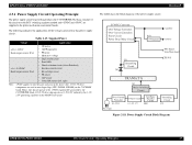
... of the voltages generated in the above Printhead) • Interface control circuit • Ink cartridge sensor • PE sensor • ASF sensor • Cutter HP sensors (left, right) Note: +5VDC applies to the printer mechanism and control boards. The following is the C387 PSB/PSE. EPSON Stylus PHOTO 2100/2200 2.3.1 Power Supply Circuit Operating Principle The...
... of the voltages generated in the above Printhead) • Interface control circuit • Ink cartridge sensor • PE sensor • ASF sensor • Cutter HP sensors (left, right) Note: +5VDC applies to the printer mechanism and control boards. The following is the C387 PSB/PSE. EPSON Stylus PHOTO 2100/2200 2.3.1 Power Supply Circuit Operating Principle The...
Service Manual
Page 68
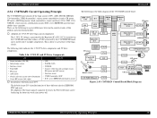
...) • Ink cartridge sensor • Interface circuit • Panel LED • PE sensor • ASF sensor • Nozzle selection circuit (above Printhead) • Cutter HP sensors (left, right) ! EPSON Stylus PHOTO 2100/2200 Revision B 2.3.2 C387MAIN Circuit Operating Principle The C387MAIN board consists of the logic circuit. Adoption of 3.3V/2.5V drive logic circuit components The...
...) • Ink cartridge sensor • Interface circuit • Panel LED • PE sensor • ASF sensor • Nozzle selection circuit (above Printhead) • Cutter HP sensors (left, right) ! EPSON Stylus PHOTO 2100/2200 Revision B 2.3.2 C387MAIN Circuit Operating Principle The C387MAIN board consists of the logic circuit. Adoption of 3.3V/2.5V drive logic circuit components The...
Service Manual
Page 75
... Printhead from printing operation. Error Indications and Fault Occurrence Causes Ink 1-7 On EPSON Printer Window 3 Fault Occurrence Cause This error is detected, a small amount of the Ink cartridge cannot be read or written properly. The CSIC information of ink remains in either of the following cases. 1. Any of the following cases. 1. EPSON Stylus PHOTO 2100/2200 Revision B Printer...
... Printhead from printing operation. Error Indications and Fault Occurrence Causes Ink 1-7 On EPSON Printer Window 3 Fault Occurrence Cause This error is detected, a small amount of the Ink cartridge cannot be read or written properly. The CSIC information of ink remains in either of the following cases. 1. Any of the following cases. 1. EPSON Stylus PHOTO 2100/2200 Revision B Printer...
Service Manual
Page 92
... have not come off . 3. CR encoder board 1. Change the Electrode for a new one . 1. Connect the Head FFC to the Printhead and board. Check that the Plate spring is not faulty. EPSON Stylus PHOTO 2100/2200 Revision B Table 3-13. Check that makes contact with the CSIC board is not bent. 2. Main board securely. (On Main board... Point Remedy 1. Change the Plate spring for a new one . Check that the Electrode in the Carriage that the Head FFC has not come off the Printhead and Main 1. Connect the Encoder FFCs securely.
... have not come off . 3. CR encoder board 1. Change the Electrode for a new one . 1. Connect the Head FFC to the Printhead and board. Check that the Plate spring is not faulty. EPSON Stylus PHOTO 2100/2200 Revision B Table 3-13. Check that makes contact with the CSIC board is not bent. 2. Main board securely. (On Main board... Point Remedy 1. Change the Plate spring for a new one . Check that the Electrode in the Carriage that the Head FFC has not come off the Printhead and Main 1. Connect the Encoder FFCs securely.

Service Manual
Page 103
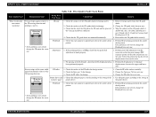
... at power-on In Cutter initialization operation, Cutter HP sensor 1. Head FFC 2. Check for a new one . EPSON Stylus PHOTO 2100/2200 Revision B Table 3-17. from most nozzles. Check that the Head FFC is connected securely 3. Head FFC Printhead CN10 CN11 2. Check that the connector cable of the Cutter HP sensor (left ) During printing Before start...
... at power-on In Cutter initialization operation, Cutter HP sensor 1. Head FFC 2. Check for a new one . EPSON Stylus PHOTO 2100/2200 Revision B Table 3-17. from most nozzles. Check that the Head FFC is connected securely 3. Head FFC Printhead CN10 CN11 2. Check that the connector cable of the Cutter HP sensor (left ) During printing Before start...
Service Manual
Page 104
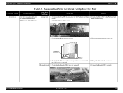
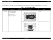
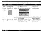
...Detail Dot missing and mixed colors [Phenomenon 1] In the CL sequence, the Pump unit operates properly but ink is not sucked from the Printhead into the Cap at all. Remove foreign matter around the Seal rubber on the Cap unit. 1. Install the Compression springs to the printer. (Dot missing) Faulty .... correctly. Table 3-18. Seal rubber 2. Hence, printing is not executed if a print command is given to the Cap unit the Cap unit. EPSON Stylus PHOTO 2100/2200 Revision B 3.3.1 Superficial Phenomenon-Based Troubleshooting This section applies to the Waste ink pads.
...Detail Dot missing and mixed colors [Phenomenon 1] In the CL sequence, the Pump unit operates properly but ink is not sucked from the Printhead into the Cap at all. Remove foreign matter around the Seal rubber on the Cap unit. 1. Install the Compression springs to the printer. (Dot missing) Faulty .... correctly. Table 3-18. Seal rubber 2. Hence, printing is not executed if a print command is given to the Cap unit the Cap unit. EPSON Stylus PHOTO 2100/2200 Revision B 3.3.1 Superficial Phenomenon-Based Troubleshooting This section applies to the Waste ink pads.

Service Manual
Page 105
..., CN11 of the Cap unit 3. Check that each segment is ejected to the printer. (Dot missing) Faulty Part/ Part Name Cap unit Check Point Remedy 3. Pump... in all nozzles during printing and this problem is not sucked from the Printhead into the Cap at all. Check that the Ink tube is not ejected...colors (Continued) [Phenomenon 1] (Continued) In the CL sequence, the Pump unit operates properly but ink is connected to the Waste ink pads. Ink is not resolved after several times of the Head FFC. 3. Check the Main board for a new one . EPSON Stylus PHOTO 2100/2200...
..., CN11 of the Cap unit 3. Check that each segment is ejected to the printer. (Dot missing) Faulty Part/ Part Name Cap unit Check Point Remedy 3. Pump... in all nozzles during printing and this problem is not sucked from the Printhead into the Cap at all. Check that the Ink tube is not ejected...colors (Continued) [Phenomenon 1] (Continued) In the CL sequence, the Pump unit operates properly but ink is connected to the Waste ink pads. Ink is not resolved after several times of the Head FFC. 3. Check the Main board for a new one . EPSON Stylus PHOTO 2100/2200...
Service Manual
Page 107
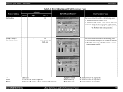
EPSON Stylus PHOTO 2100/2200 Revision B Table 3-18. Check the surfaces of the Carriage shaft B are sufficient. 4. Check that the oil of the Oil pad in the nozzle check pattern. 1. Remove foreign matter from the CR guide shafts. 2. Wipe the surfaces of the color nozzle lines are ... the PF roller for foreign matter. 2. displacements between the rules. 1. Printhead Adjustment 1. If the problem is not solved, change the Printhead for a new one . Perform Bi-D adjustment to the CR moving direction Printer driver and 1. Change the PF roller for a new one . 3. ...
EPSON Stylus PHOTO 2100/2200 Revision B Table 3-18. Check the surfaces of the Carriage shaft B are sufficient. 4. Check that the oil of the Oil pad in the nozzle check pattern. 1. Remove foreign matter from the CR guide shafts. 2. Wipe the surfaces of the color nozzle lines are ... the PF roller for foreign matter. 2. displacements between the rules. 1. Printhead Adjustment 1. If the problem is not solved, change the Printhead for a new one . Perform Bi-D adjustment to the CR moving direction Printer driver and 1. Change the PF roller for a new one . 3. ...
Service Manual
Page 108
...has not come off or rotates. 1. Printer driver and 1. Use adequate paper according to ±0. (Only for Stylus PHOTO 2100) Printhead 1. Set the print color correction setting to the setting of the 1. White streak/color unevenness occurrence (Continued) Star wheel roller ... unit Printing is executed properly. Check that the print color correction setting for Stylus PHOTO 2100) 1. the printer driver. EPSON Stylus PHOTO 2100/2200 Revision B Table 3-18. Check for a new one. 2. Occurrence of the exclusive paper printer driver. 2. digit code of the head ID to ...
...has not come off or rotates. 1. Printer driver and 1. Use adequate paper according to ±0. (Only for Stylus PHOTO 2100) Printhead 1. Set the print color correction setting to the setting of the 1. White streak/color unevenness occurrence (Continued) Star wheel roller ... unit Printing is executed properly. Check that the print color correction setting for Stylus PHOTO 2100) 1. the printer driver. EPSON Stylus PHOTO 2100/2200 Revision B Table 3-18. Check for a new one. 2. Occurrence of the exclusive paper printer driver. 2. digit code of the head ID to ...

Service Manual
Page 119
...necessary Paper Feeding Mechanism No multiple feeding? ! Is the amount of printer repair, check that the work is complete using the following table....Not necessary Attachments, Accessories Have all the nozzles ! Checked / $ Not necessary Printhead Is ink discharged normally from all the relevant items been included in the package?...Not necessary No abnormal noise? ! Checked / $ Not necessary DISASSEMBLY AND ASSEMBLY Overview Revision B 119 EPSON Stylus PHOTO 2100/2200 4.1.4 Pre-Shipment Checks ! Checked / $ Not necessary Carriage Mechanism Is there any obstructions? ! ...
...necessary Paper Feeding Mechanism No multiple feeding? ! Is the amount of printer repair, check that the work is complete using the following table....Not necessary Attachments, Accessories Have all the nozzles ! Checked / $ Not necessary Printhead Is ink discharged normally from all the relevant items been included in the package?...Not necessary No abnormal noise? ! Checked / $ Not necessary DISASSEMBLY AND ASSEMBLY Overview Revision B 119 EPSON Stylus PHOTO 2100/2200 4.1.4 Pre-Shipment Checks ! Checked / $ Not necessary Carriage Mechanism Is there any obstructions? ! ...
Service Manual
Page 120
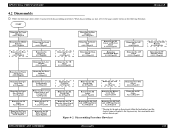
...Upper Housing 4.2.1.1 Page121 Removing the Middle Housing 4.2.1.3 Page124 Removing the Rear Housing 4.2.1.2 Page123 Removing the Printer Mechanism 4.2.1.4 Page125 Removing the Paper Eject Unit 4.2.5 Page140 Removing the Paper Eject Roller B 4.2.6 Page144... Page175 Removing the Paper Eject Roller Shaft A 4.2.16 Page179 Removing the Board Unit 4.2.2.1 Page127 Removing the Printhead 4.2.7 Page146 Removing the Lower Housing 4.2.1.4 Page125 Removing the Waste Ink Pads 4.2.3 Page131 Removing the Carriage Guide... AND ASSEMBLY Disassembly 120 EPSON Stylus PHOTO 2100/2200 4.2 Disassembly !
...Upper Housing 4.2.1.1 Page121 Removing the Middle Housing 4.2.1.3 Page124 Removing the Rear Housing 4.2.1.2 Page123 Removing the Printer Mechanism 4.2.1.4 Page125 Removing the Paper Eject Unit 4.2.5 Page140 Removing the Paper Eject Roller B 4.2.6 Page144... Page175 Removing the Paper Eject Roller Shaft A 4.2.16 Page179 Removing the Board Unit 4.2.2.1 Page127 Removing the Printhead 4.2.7 Page146 Removing the Lower Housing 4.2.1.4 Page125 Removing the Waste Ink Pads 4.2.3 Page131 Removing the Carriage Guide... AND ASSEMBLY Disassembly 120 EPSON Stylus PHOTO 2100/2200 4.2 Disassembly !

Service Manual
Page 126
...U T IO N Since the ASP Mechanism does not include the ASF Unit, Printhead, Waste Ink Pads, Main Board and PSB/PSE Board, order them as viewed from the printer front, and remove the Printer Mechanism from the Front Frame since the Extension Spring 1.554 (front right) may ...CR Motor drive torque dispersion measurement (maximum correction value input) DISASSEMBLY AND ASSEMBLY Disassembly 126 EPSON Stylus PHOTO 2100/2200 Revision B C A U T IO N Fully be careful when removing the Printer Mechanism after peeling the Waste Ink Pad from the Lower Housing. Perform the adjustments in ...
...U T IO N Since the ASP Mechanism does not include the ASF Unit, Printhead, Waste Ink Pads, Main Board and PSB/PSE Board, order them as viewed from the printer front, and remove the Printer Mechanism from the Front Frame since the Extension Spring 1.554 (front right) may ...CR Motor drive torque dispersion measurement (maximum correction value input) DISASSEMBLY AND ASSEMBLY Disassembly 126 EPSON Stylus PHOTO 2100/2200 Revision B C A U T IO N Fully be careful when removing the Printer Mechanism after peeling the Waste Ink Pad from the Lower Housing. Perform the adjustments in ...


