
Owners Manual
Page 6
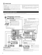
... MD recorder, CD recorder or other components. RL R L L R RL CD player or other component equipped with digital output. For details, see "Setting the Trigger Out Setup" on setting this unit's CD jacks using pin plug cords. 6 Connecting a tape deck Connections for hair driers, etc. • Note that they do not obstruct...
... MD recorder, CD recorder or other components. RL R L L R RL CD player or other component equipped with digital output. For details, see "Setting the Trigger Out Setup" on setting this unit's CD jacks using pin plug cords. 6 Connecting a tape deck Connections for hair driers, etc. • Note that they do not obstruct...
Owners Manual
Page 9
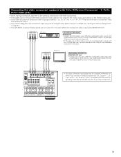
... not output from the color difference (component) video output jacks (MONITOR OUT). For details, see "Setting the video In Assignment" on page 24. • The AVR-2803's on some TVs, monitors or video components ("CR, CB and Y", "RY, B-Y and Y", "Pr, Pb and Y", etc.). For details, carefully read the operating instructions included with... COMPONENT VIDEO-1 IN jack using 75 Ω/ohms coaxial video pin-plug cords. • The color difference input jacks may be changed at the system setup.
... not output from the color difference (component) video output jacks (MONITOR OUT). For details, see "Setting the video In Assignment" on page 24. • The AVR-2803's on some TVs, monitors or video components ("CR, CB and Y", "RY, B-Y and Y", "Pr, Pb and Y", etc.). For details, carefully read the operating instructions included with... COMPONENT VIDEO-1 IN jack using 75 Ω/ohms coaxial video pin-plug cords. • The color difference input jacks may be changed at the system setup.
Owners Manual
Page 15
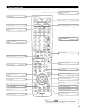
...~41) ZONE1 (MAIN) buttons 47) Tuner system/System buttons 32, 35, 47, 61~63) MODE SELECT button 32) System buttons 32, 34, 35, 38) SYSTEM SETUP/SETUP button 17, 30, 34) Cursor buttons 16) ON SCREEN/DISPLAY button ....(34, 35, 46) TEST TONE button 49) SYSTEM CALL buttons 37) USE/LEARN button..., 35) FRONT SPEAKER button 41) SURROUND BACK button 53) INPUT MODE selector buttons 42, 44) NOTE: • The shaded button do not function with the AVR-2803/983. (Nothing happens when they are pressed.) 15
...~41) ZONE1 (MAIN) buttons 47) Tuner system/System buttons 32, 35, 47, 61~63) MODE SELECT button 32) System buttons 32, 34, 35, 38) SYSTEM SETUP/SETUP button 17, 30, 34) Cursor buttons 16) ON SCREEN/DISPLAY button ....(34, 35, 46) TEST TONE button 49) SYSTEM CALL buttons 37) USE/LEARN button..., 35) FRONT SPEAKER button 41) SURROUND BACK button 53) INPUT MODE selector buttons 42, 44) NOTE: • The shaded button do not function with the AVR-2803/983. (Nothing happens when they are pressed.) 15
Owners Manual
Page 16
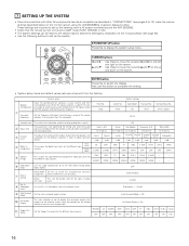
... as described in order to the left and right on -screen display function. Set the frequency (Hz) below on the monitor screen using the AVR-2803/983's on the screen. Front Sp. Small / 2spkrs 80 Hz Subwoofer mode This selects the subwoofer speaker for the different input sources. e...Mode = ON On Screen Display = ON !1 Trigger Out Setup Set the Trigger Out output for the different channels in "CONNECTIONS" (see page 63). • Use the following buttons to set up the listening room's AV system centered around the AVR-2803/983. • Check that appears on the monitor screen...
... as described in order to the left and right on -screen display function. Set the frequency (Hz) below on the monitor screen using the AVR-2803/983's on the screen. Front Sp. Small / 2spkrs 80 Hz Subwoofer mode This selects the subwoofer speaker for the different input sources. e...Mode = ON On Screen Display = ON !1 Trigger Out Setup Set the Trigger Out output for the different channels in "CONNECTIONS" (see page 63). • Use the following buttons to set up the listening room's AV system centered around the AVR-2803/983. • Check that appears on the monitor screen...

Owners Manual
Page 17
...up to lock the system setup settings so that all the connections are output with priority to the AVR-2803/983's video input connectors. (For instructions on the main unit's power. 2 Display the System Setup Menu. System setup can reset it is connected to both the AVR-2803/983's S-Video and ...video monitor output jacks and signals are input to the AVR-2803/983 from the System Setup Menu screen. A1 ~ A8 B1 ~ B8 C1 ~ C8 D1 ...
...up to lock the system setup settings so that all the connections are output with priority to the AVR-2803/983's video input connectors. (For instructions on the main unit's power. 2 Display the System Setup Menu. System setup can reset it is connected to both the AVR-2803/983's S-Video and ...video monitor output jacks and signals are input to the AVR-2803/983 from the System Setup Menu screen. A1 ~ A8 B1 ~ B8 C1 ~ C8 D1 ...
Owners Manual
Page 18
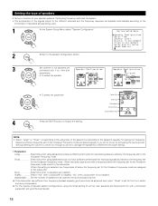
... speakers are installed. Front Sp. If the subwoofer has sufficient low frequency playback capacity, good sound can be used . 1 At the System Setup Menu select "Speaker Configuration". 2 Switch to the speaker configuration screen. 3 Set whether or not speakers are connected and, if so, their size...front, center and surround speakers. Setting the type of speakers • Set up in function of your speaker systems. Performing this setup optimizes the system. • The composition of the signals output to the different channels and the frequency response are adjusted automatically ...
... speakers are installed. Front Sp. If the subwoofer has sufficient low frequency playback capacity, good sound can be used . 1 At the System Setup Menu select "Speaker Configuration". 2 Switch to the speaker configuration screen. 3 Set whether or not speakers are connected and, if so, their size...front, center and surround speakers. Setting the type of speakers • Set up in function of your speaker systems. Performing this setup optimizes the system. • The composition of the signals output to the different channels and the frequency response are adjusted automatically ...
Owners Manual
Page 19
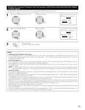
... 3 Enter the setting. For details, refer to 80 Hz. NOTES: - The low frequency signal range of the subwoofer mode setting in the setup menu. NOTE: For ordinary speaker systems, we recommend setting the crossover frequency to "Surround Modes and Parameters" on the size and shape of the...distribution when playing Dolby Digital and DTS signals • Set the crossover frequency and subwoofer mode according to the subwoofer channel. The System Setup Menu reappears. In this playback mode, the low frequency range expand more uniformly through the room, but depending on page 60. 19...
... 3 Enter the setting. For details, refer to 80 Hz. NOTES: - The low frequency signal range of the subwoofer mode setting in the setup menu. NOTE: For ordinary speaker systems, we recommend setting the crossover frequency to "Surround Modes and Parameters" on the size and shape of the...distribution when playing Dolby Digital and DTS signals • Set the crossover frequency and subwoofer mode according to the subwoofer channel. The System Setup Menu reappears. In this playback mode, the low frequency range expand more uniformly through the room, but depending on page 60. 19...

Owners Manual
Page 20
... the distances between subwoofer and listening position FL Center FR Subwoofer L1 L2 L5 Listening position SL L3 L4 SR SBL SBR 1 At the System Setup Menu select "Delay Time". 2 Switch to the Delay Time screen. 3 Select the desired unit, meters or feet. L1: Distance between center speaker and listening position...
... the distances between subwoofer and listening position FL Center FR Subwoofer L1 L2 L5 Listening position SL L3 L4 SR SBL SBR 1 At the System Setup Menu select "Delay Time". 2 Switch to the Delay Time screen. 3 Select the desired unit, meters or feet. L1: Distance between center speaker and listening position...

Owners Manual
Page 21
The System Setup Menu reappears. The AVR-2803/983 automatically sets the optimum surround delay time for "Default", the settings are reset to the factory default values (see page 49.) 1 At the System Setup Menu select "Channel Level". 2 Switch to the Channel Level screen. 3 Select "Test Tone". 21 Select the value closest to the measured...
The System Setup Menu reappears. The AVR-2803/983 automatically sets the optimum surround delay time for "Default", the settings are reset to the factory default values (see page 49.) 1 At the System Setup Menu select "Channel Level". 2 Switch to the Channel Level screen. 3 Select "Test Tone". 21 Select the value closest to the measured...
Owners Manual
Page 23
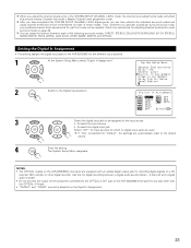
...be recalled. The System Setup Menu reappears. After you have completed the SYSTEM SETUP CHANNEL LEVEL adjustments, you can adjust the channel levels for each of those modes. Setting the Digital In Assignment • This setting assigns the digital input jacks of the AVR-2803/983 for the different ...input sources. 1 At the System Setup Menu select "Digital In Assignment". 2 Switch to the Digital Inputs screen. 3 Select the digital input jack...
...be recalled. The System Setup Menu reappears. After you have completed the SYSTEM SETUP CHANNEL LEVEL adjustments, you can adjust the channel levels for each of those modes. Setting the Digital In Assignment • This setting assigns the digital input jacks of the AVR-2803/983 for the different ...input sources. 1 At the System Setup Menu select "Digital In Assignment". 2 Switch to the Digital Inputs screen. 3 Select the digital input jack...

Owners Manual
Page 24
...) video input jacks of speakers being used . Setting the Dolby Digital Setup Sets the down-mixing method when not using a center speaker or surround speakers, the sound is compressed automatically according to the combination of the AVR-2803/983 for which the component (Y, PB/CB and PR/CR) video ...input is not to be assigned to "ON". ON: The dynamic range is played from the front speakers. The System Setup Menu reappears. NOTE: When not using a ...
...) video input jacks of speakers being used . Setting the Dolby Digital Setup Sets the down-mixing method when not using a center speaker or surround speakers, the sound is compressed automatically according to the combination of the AVR-2803/983 for which the component (Y, PB/CB and PR/CR) video ...input is not to be assigned to "ON". ON: The dynamic range is played from the front speakers. The System Setup Menu reappears. NOTE: When not using a ...

Owners Manual
Page 25
...this setting to switch the power amplifier for the surround back channel to use as Zone 2 out. BACK/ZONE2 PREOUT" terminals. 1 At the System Setup Menu select "Zone2 Control" and press the ENTER button. 2 The "Zone2 Control" screen appears. level Set the Zone 2 pre-out output level ...adjustment. 1 At the System Setup Menu select "Zone2 Control" and press the ENTER button. 25 If ZONE2 is selected, the signal that selected at ZONE2 is selected 4 Enter the ...
...this setting to switch the power amplifier for the surround back channel to use as Zone 2 out. BACK/ZONE2 PREOUT" terminals. 1 At the System Setup Menu select "Zone2 Control" and press the ENTER button. 2 The "Zone2 Control" screen appears. level Set the Zone 2 pre-out output level ...adjustment. 1 At the System Setup Menu select "Zone2 Control" and press the ENTER button. 25 If ZONE2 is selected, the signal that selected at ZONE2 is selected 4 Enter the ...

Owners Manual
Page 26
...longer be selected.) 4 Enter the setting. Also refer to the specifications of the analog input signal connected to the Ext.In Subwoofer. 1 At the System Setup Menu select "Ext.In Subwoofer Level". 2 Switch to the Ext.In Subwoofer Level screen. 3 Select the desired setting. At the "Zone2 Control" screen... • Set the method of playback of the player being used. Level" and press the ENTER button. 3 Select the desired setting. The System Setup Menu reappears. 26 Variable: The level can be adjusted freely using the buttons on the remote control unit. 0 dB, -40 dB: The output ...
...longer be selected.) 4 Enter the setting. Also refer to the specifications of the analog input signal connected to the Ext.In Subwoofer. 1 At the System Setup Menu select "Ext.In Subwoofer Level". 2 Switch to the Ext.In Subwoofer Level screen. 3 Select the desired setting. At the "Zone2 Control" screen... • Set the method of playback of the player being used. Level" and press the ENTER button. 3 Select the desired setting. The System Setup Menu reappears. 26 Variable: The level can be adjusted freely using the buttons on the remote control unit. 0 dB, -40 dB: The output ...
Owners Manual
Page 27
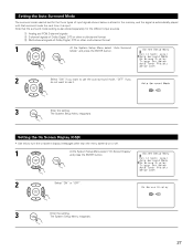
... (OSD) • Use this to turn the on-screen display (messages other multi-channel format 1 At the System Setup Menu select "Auto Surround Mode" and press the ENTER button. 2 Select "ON" if you want to use the... DTS or other than the menu screens) on or off. 1 At the System Setup Menu select "On Screen Display" and press the ENTER button. 2 Select "ON" or "OFF". 3 Enter the... setting. The System Setup Menu reappears. Note that surround mode the next time it . 3 Enter the setting. q Analog and PCM...
... (OSD) • Use this to turn the on-screen display (messages other multi-channel format 1 At the System Setup Menu select "Auto Surround Mode" and press the ENTER button. 2 Select "ON" if you want to use the... DTS or other than the menu screens) on or off. 1 At the System Setup Menu select "On Screen Display" and press the ENTER button. 2 Select "ON" or "OFF". 3 Enter the... setting. The System Setup Menu reappears. Note that surround mode the next time it . 3 Enter the setting. q Analog and PCM...

Owners Manual
Page 28
... this to automatically search for the different input sources. 1 At the System Setup Menu select "Trigger Out Setup". 2 Switch to the Trigger Out Setup screen. 3 Select the input source and select "ON" or "OFF". 4 Enter the setting. Setting the Trigger Out Setup • Sets the Trigger Out output for FM broadcasts and store up... to poor reception, use the "Manual tuning" operation to tune in the station, then preset it using the manual "Preset memory" operation. 1 At the System Setup Menu select "Auto Tuner Presets". 2 Switch to the Auto Preset Memory screen. 28 The System...
... this to automatically search for the different input sources. 1 At the System Setup Menu select "Trigger Out Setup". 2 Switch to the Trigger Out Setup screen. 3 Select the input source and select "ON" or "OFF". 4 Enter the setting. Setting the Trigger Out Setup • Sets the Trigger Out output for FM broadcasts and store up... to poor reception, use the "Manual tuning" operation to tune in the station, then preset it using the manual "Preset memory" operation. 1 At the System Setup Menu select "Auto Tuner Presets". 2 Switch to the Auto Preset Memory screen. 28 The System...
Owners Manual
Page 29
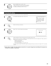
... to screen. Protecting the setting The system setup settings can be locked so that they cannot be changed easily. 1 At the System Setup Menu select "Setup Lock". 2 Switch to the Setup Lock screen. 3 Select "ON", to lock the system setup settings. 4 Press the ENTER to change ...or the speakers are repositioned. 29 The display automatically switches to select "Yes". When the setup lock function is activated, the settings listed below cannot be changed , and "Setup Locked" is completed. "Completed" appears once searching is displayed when related buttons are made, ...
... to screen. Protecting the setting The system setup settings can be locked so that they cannot be changed easily. 1 At the System Setup Menu select "Setup Lock". 2 Switch to the Setup Lock screen. 3 Select "ON", to lock the system setup settings. 4 Press the ENTER to change ...or the speakers are repositioned. 29 The display automatically switches to select "Yes". When the setup lock function is activated, the settings listed below cannot be changed , and "Setup Locked" is completed. "Completed" appears once searching is displayed when related buttons are made, ...

Owners Manual
Page 30
... can be pressed at any time during the system setup process to the S-video MONITOR OUT video signal output jack. 30 The changed settings are entered and the on-screen display turns off. • On-screen display signals Signals input to the AVR-2803 VIDEO signal input jack (yellow) S-video signal input jack... output to the VIDEO MONITOR OUT video signal output jack (yellow) if the monitor TV is not connected to complete the process. 1 At the System Setup Menu, press the SYSTEM...
... can be pressed at any time during the system setup process to the S-video MONITOR OUT video signal output jack. 30 The changed settings are entered and the on-screen display turns off. • On-screen display signals Signals input to the AVR-2803 VIDEO signal input jack (yellow) S-video signal input jack... output to the VIDEO MONITOR OUT video signal output jack (yellow) if the monitor TV is not connected to complete the process. 1 At the System Setup Menu, press the SYSTEM...

Owners Manual
Page 34
...components. 2 Operate the component. • For details, refer to manufacturer. Compare with this remote control unit. 1. Digital video disc player (DVD, DVD SETUP) system buttons POWER : Power on /standby (ON/SOURCE) 6,7 : Manual search (forward and reverse) 2 : Stop 1 : Play 8,9 : Auto ... a component stored in the preset memory 1 Press the mode selector button for DVD changer only) DISPLAY : Display MENU : Menu RETURN : Return SETUP : Setup ENTER : Enter •, ª, 0, 1 : Cursor up, down, left and right 2. Some models cannot be operated with the remote control...
...components. 2 Operate the component. • For details, refer to manufacturer. Compare with this remote control unit. 1. Digital video disc player (DVD, DVD SETUP) system buttons POWER : Power on /standby (ON/SOURCE) 6,7 : Manual search (forward and reverse) 2 : Stop 1 : Play 8,9 : Auto ... a component stored in the preset memory 1 Press the mode selector button for DVD changer only) DISPLAY : Display MENU : Menu RETURN : Return SETUP : Setup ENTER : Enter •, ª, 0, 1 : Cursor up, down, left and right 2. Some models cannot be operated with the remote control...
Owners Manual
Page 43
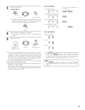
... is set the input mode to the component's manual. 5 Adjust the volume. If the DIGITAL indicator does not light, check whether the digital input component setup (page 23) and connections are correct and whether the component's power is "18 dB - (Maximum value of channel level)".) Input mode when playing DTS sources...
... is set the input mode to the component's manual. 5 Adjust the volume. If the DIGITAL indicator does not light, check whether the digital input component setup (page 23) and connections are correct and whether the component's power is "18 dB - (Maximum value of channel level)".) Input mode when playing DTS sources...

Owners Manual
Page 47
... the ZONE2 SOURCE function is set to TUNER, the preset channel can be output. • For operating instructions, refer to an amplifier, etc., in System Setup Menu. (See page 26) DEFAULT SETTING (ZONE2 VOLUME LEVEL) : - - - [2] Outputting a program source to the manuals of the respective components. 5 To cancel, turn the FUNCTION knob...
... the ZONE2 SOURCE function is set to TUNER, the preset channel can be output. • For operating instructions, refer to an amplifier, etc., in System Setup Menu. (See page 26) DEFAULT SETTING (ZONE2 VOLUME LEVEL) : - - - [2] Outputting a program source to the manuals of the respective components. 5 To cancel, turn the FUNCTION knob...


