
Owners Manual
Page 1
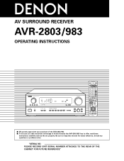
PLEASE RECORD UNIT SERIAL NUMBER ATTACHED TO THE REAR OF THE CABINET FOR FUTURE REFERENCE" AV SURROUND RECEIVER AVR-2803/983 OPERATING INSTRUCTIONS REMOTE SENSOR ON / STANDBY AUTO SIGNAL DIGITAL SURROUND BACK CH OUTPUT INPUT PCM DTS SIGNAL DETECT VOLUME LEVEL 2 We greatly appreciate your purchase of the AVR-2803/983. 2 To be sure you take maximum advantage of all the features the AVR-2803/983 has to keep this manual for future reference, should any questions or problems arise. Be sure to offer, read these instructions carefully and use the set properly. "SERIAL NO.
PLEASE RECORD UNIT SERIAL NUMBER ATTACHED TO THE REAR OF THE CABINET FOR FUTURE REFERENCE" AV SURROUND RECEIVER AVR-2803/983 OPERATING INSTRUCTIONS REMOTE SENSOR ON / STANDBY AUTO SIGNAL DIGITAL SURROUND BACK CH OUTPUT INPUT PCM DTS SIGNAL DETECT VOLUME LEVEL 2 We greatly appreciate your purchase of the AVR-2803/983. 2 To be sure you take maximum advantage of all the features the AVR-2803/983 has to keep this manual for future reference, should any questions or problems arise. Be sure to offer, read these instructions carefully and use the set properly. "SERIAL NO.
Owners Manual
Page 4
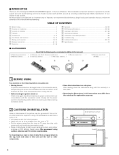
... following parts are not problems with the warranty in a safe place. • Note that all other audio components when moving the set for choosing the DENON AVR-2803/983 Digital A / V Surround Receiver. We recommend using this unit: • Moving the set To prevent short circuits or damaged wires in a safe place. Operation 41... and 75 Ω/ohms coaxial cables. Wall 4 After reading, store this instructions along with the connection cords. 2 INTRODUCTION Thank you review the contents of this manual before proceeding.
... following parts are not problems with the warranty in a safe place. • Note that all other audio components when moving the set for choosing the DENON AVR-2803/983 Digital A / V Surround Receiver. We recommend using this unit: • Moving the set To prevent short circuits or damaged wires in a safe place. Operation 41... and 75 Ω/ohms coaxial cables. Wall 4 After reading, store this instructions along with the connection cords. 2 INTRODUCTION Thank you review the contents of this manual before proceeding.

Owners Manual
Page 8
... The input selectors for the S inputs and Video inputs work in conjunction with S-Video jacks • When making connections, also refer to the equipment's instruction manuals. Connecting a DVD player or a video disc player (VDP) DVD • Connect the DVD player's S-Video output jack to the V.AUX jacks. S-VIDEO OUT DVD player...
... The input selectors for the S inputs and Video inputs work in conjunction with S-Video jacks • When making connections, also refer to the equipment's instruction manuals. Connecting a DVD player or a video disc player (VDP) DVD • Connect the DVD player's S-Video output jack to the V.AUX jacks. S-VIDEO OUT DVD player...
Owners Manual
Page 22
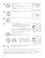
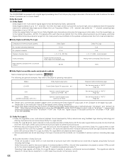
If the "Auto" mode is selected 5 Select "Test Tone Start". 6 Select "Yes". 7 a. When the "Manual" mode is selected Use the CURSOR up and down to select the speaker for which you want to output test tones, then use a well known ... test tones from which you may also need to "1spkr" for natural balance. Select "Auto" or "Manual". • Auto: Adjust the level while listening to the test tones produced automatically from the different speakers. • Manual: Select the speaker from the various speakers is set to adjust the subwoofer's own volume control...
If the "Auto" mode is selected 5 Select "Test Tone Start". 6 Select "Yes". 7 a. When the "Manual" mode is selected Use the CURSOR up and down to select the speaker for which you want to output test tones, then use a well known ... test tones from which you may also need to "1spkr" for natural balance. Select "Auto" or "Manual". • Auto: Adjust the level while listening to the test tones produced automatically from the different speakers. • Manual: Select the speaker from the various speakers is set to adjust the subwoofer's own volume control...

Owners Manual
Page 28
... 8 and E1 to 8. NOTE: • If an FM station cannot be preset automatically due to poor reception, use the "Manual tuning" operation to tune in the station, then preset it using the manual "Preset memory" operation. 1 At the System Setup Menu select "Auto Tuner Presets". 2 Switch to the Trigger Out Setup screen...
... 8 and E1 to 8. NOTE: • If an FM station cannot be preset automatically due to poor reception, use the "Manual tuning" operation to tune in the station, then preset it using the manual "Preset memory" operation. 1 At the System Setup Menu select "Auto Tuner Presets". 2 Switch to the Trigger Out Setup screen...

Owners Manual
Page 32
...audio component. • For details, refer to operate some models. 1. MD recorder (MD), CD recorder (CDR) system buttons 4. Operating DENON audio components 1 Use the mode selector buttons to select the component you want to beginning of track) 3 : Pause DISC SKIP +: (for... CD changers only) 6 : Rewind 7 : Fast forward 2 : Stop 1 : Forward play 3 : Pause 0 : Reverse play A/B : Switch between AUTO and MANUAL MEMORY : Preset memory SHIFT : Switch preset channel range CHANNEL +, - : Preset channel up /down BAND : Switch between AM and FM bands MODE : Switch between sides ...
...audio component. • For details, refer to operate some models. 1. MD recorder (MD), CD recorder (CDR) system buttons 4. Operating DENON audio components 1 Use the mode selector buttons to select the component you want to beginning of track) 3 : Pause DISC SKIP +: (for... CD changers only) 6 : Rewind 7 : Fast forward 2 : Stop 1 : Forward play 3 : Pause 0 : Reverse play A/B : Switch between AUTO and MANUAL MEMORY : Preset memory SHIFT : Switch preset channel range CHANNEL +, - : Preset channel up /down BAND : Switch between AM and FM bands MODE : Switch between sides ...

Owners Manual
Page 34
Compare with this remote control unit. 1. Video disc player (VDP) system buttons POWER : Power on /standby (ON/SOURCE) 6,7 : Manual search (forward and reverse) 2 : Stop 1 : Play 8,9 : Auto search (to beginning of the various components. 2 Operate the component....names may differ according to the component's operating instructions. Digital video disc player (DVD, DVD SETUP) system buttons POWER : Power on /standby (ON/SOURCE) 6,7 : Manual search (forward and reverse) 2 : Stop 1 : Play 8,9 : Auto search (cue) 3 : Pause 0~9, +10 : 10 key 34 Operating a component stored in...
Compare with this remote control unit. 1. Video disc player (VDP) system buttons POWER : Power on /standby (ON/SOURCE) 6,7 : Manual search (forward and reverse) 2 : Stop 1 : Play 8,9 : Auto search (to beginning of the various components. 2 Operate the component....names may differ according to the component's operating instructions. Digital video disc player (DVD, DVD SETUP) system buttons POWER : Power on /standby (ON/SOURCE) 6,7 : Manual search (forward and reverse) 2 : Stop 1 : Play 8,9 : Auto search (cue) 3 : Pause 0~9, +10 : 10 key 34 Operating a component stored in...

Owners Manual
Page 35
... DISPLAY : Switch display RETURN : Return NOTES: • For this CD, CDR, MD and TAPE components, buttons can be operated in the same way as for Denon audio components. • The television can be operated in the DVD/VDP, VCR and TV modes. 35 Monitor TV (TV), digital broadcast satellite (DBS) tuner...
... DISPLAY : Switch display RETURN : Return NOTES: • For this CD, CDR, MD and TAPE components, buttons can be operated in the same way as for Denon audio components. • The television can be operated in the DVD/VDP, VCR and TV modes. 35 Monitor TV (TV), digital broadcast satellite (DBS) tuner...

Owners Manual
Page 38
For example, when the CD mode is set to the punch through mode in the TV mode, the CD mode's PLAY, STOP, MANUAL SEARCH, AUTO SEARCH, PAUSE and DISC SKIP buttons' signals are sent in the TV mode. (2) Making the punch through . • The mode button that is ...
For example, when the CD mode is set to the punch through mode in the TV mode, the CD mode's PLAY, STOP, MANUAL SEARCH, AUTO SEARCH, PAUSE and DISC SKIP buttons' signals are sent in the TV mode. (2) Making the punch through . • The mode button that is ...
Owners Manual
Page 43
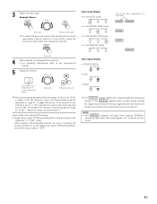
... control unit) The volume can be adjusted up to "DTS". When playing DTS-compatible sources, be sure to connect the source component to the component's manual. 5 Adjust the volume. 3 Select the play mode.
... control unit) The volume can be adjusted up to "DTS". When playing DTS-compatible sources, be sure to connect the source component to the component's manual. 5 Adjust the volume. 3 Select the play mode.

Owners Manual
Page 46
... unit's VIDEO MONITOR OUT jack. The display brightness changes in sequence. FUNCTION (Main unit) 3 Set the recording mode. • For operating instructions, refer to the manual of the component on which you want to record. 4 To cancel, turn the FUNCTION knob to select the source you wish to the Zone 2 preout...
... unit's VIDEO MONITOR OUT jack. The display brightness changes in sequence. FUNCTION (Main unit) 3 Set the recording mode. • For operating instructions, refer to the manual of the component on which you want to record. 4 To cancel, turn the FUNCTION knob to select the source you wish to the Zone 2 preout...

Owners Manual
Page 47
... off with the "MAIN ON/OFF" button. 5 4 The output level of the ZONE 2 OUT terminals can be output. • For operating instructions, refer to the manuals of the respective components. 5 To cancel, turn the FUNCTION knob and select the source you wish to output. • The indicator of ZONE 2 OUT can...
... off with the "MAIN ON/OFF" button. 5 4 The output level of the ZONE 2 OUT terminals can be output. • For operating instructions, refer to the manuals of the respective components. 5 To cancel, turn the FUNCTION knob and select the source you wish to output. • The indicator of ZONE 2 OUT can...

Owners Manual
Page 50
Use it possible to the manuals of the respective components. FL C FR SR SBR SBL 2 2 FADER SW SL 1 2 Press the 0 button to reduce the volume of the front channels, the 1 button ...
Use it possible to the manuals of the respective components. FL C FR SR SBR SBL 2 2 FADER SW SL 1 2 Press the 0 button to reduce the volume of the front channels, the 1 button ...

Owners Manual
Page 61
... set to tune in . (Main unit) (Remote control unit) (Remote control unit) NOTES: 2 Watching the display, press the BAND button to the "Manual tuning" operation. Automatic searching begins, then stops when a station is tuned in. (Remote control unit) If tuning does not stop at the desired station,... the display, press the BAND button to select the desired band (AM or FM). (Remote control unit) 3 Press the MODE button to set the manual tuning mode. 12 LISTENING TO THE RADIO • Check that the display's "AUTO" indicator turns off . 3 Press the MODE button to set the...
... set to tune in . (Main unit) (Remote control unit) (Remote control unit) NOTES: 2 Watching the display, press the BAND button to the "Manual tuning" operation. Automatic searching begins, then stops when a station is tuned in. (Remote control unit) If tuning does not stop at the desired station,... the display, press the BAND button to select the desired band (AM or FM). (Remote control unit) 3 Press the MODE button to set the manual tuning mode. 12 LISTENING TO THE RADIO • Check that the display's "AUTO" indicator turns off . 3 Press the MODE button to set the...

Owners Manual
Page 62
... to store the station in the preset memory. (Remote control unit) To preset other channels, repeat steps 2 to 5. Preset memory 1 Use the "Auto tuning" or "Manual tuning" operation to tune in the station to be checked on the on screen display. 1 Press the ON SCREEN/DISPLAY button repeatedly until the "Tuner...
... to store the station in the preset memory. (Remote control unit) To preset other channels, repeat steps 2 to 5. Preset memory 1 Use the "Auto tuning" or "Manual tuning" operation to tune in the station to be checked on the on screen display. 1 Press the ON SCREEN/DISPLAY button repeatedly until the "Tuner...

Owners Manual
Page 67
... surround sound envelopment, diffuse radiation speakers such as shown on the diagram at a narrower distance than the front speakers. • Consult the owner's manual for your subwoofer for different purposes. Surround speaker Front speaker 60 to 90 cm above ear level at the rear corners of the room facing... it at the rear center facing the front at a slightly higher position (0 to 20 cm) than the front speakers. • Consult the owner's manual for your system according to the type of the viewing position, and 60 to 90 cm As seen from the side 120° Surround speakers...
... surround sound envelopment, diffuse radiation speakers such as shown on the diagram at a narrower distance than the front speakers. • Consult the owner's manual for your subwoofer for different purposes. Surround speaker Front speaker 60 to 90 cm above ear level at the rear corners of the room facing... it at the rear center facing the front at a slightly higher position (0 to 20 cm) than the front speakers. • Consult the owner's manual for your system according to the type of the viewing position, and 60 to 90 cm As seen from the side 120° Surround speakers...
Owners Manual
Page 68
... powerful sound effects to the quietest, softest sounds, free from the lowest bass, up to 120 Hz). Please refer to the instruction manual of the adapter when making connection. 2 Some DVD digital outputs have been recorded as two channels of signals using feedback logic steering technology...of up to the player's operating instructions. When playing in a movie theater. In this case connect the "bit stream + PCM" jacks to the AVR-2803/983. (2) Dolby Pro Logic II • Dolby Pro Logic II is a new multi-channel playback format developed by Dolby Laboratories. Decoding these signals...
... powerful sound effects to the quietest, softest sounds, free from the lowest bass, up to 120 Hz). Please refer to the instruction manual of the adapter when making connection. 2 Some DVD digital outputs have been recorded as two channels of signals using feedback logic steering technology...of up to the player's operating instructions. When playing in a movie theater. In this case connect the "bit stream + PCM" jacks to the AVR-2803/983. (2) Dolby Pro Logic II • Dolby Pro Logic II is a new multi-channel playback format developed by Dolby Laboratories. Decoding these signals...
Owners Manual
Page 69
.... A DTS Digital Output logo is a multi-channel digital signal format developed by the AVR-2803/983, or may possibly cause damage to "AUTO" or "DTS" (page 42). consult the player's owner's manual for information on the same disc, so the discs can be recorded simultaneously on configuring ...other world-wide patents issued and pending. Never set the mode to "ANALOG" or "PCM". 1 Set the input mode to the speakers. Recent DENON DVD player models feature DTS-compatible digital output - q 2-channel PCM stereo signals w 2-channel Dolby Digital signals When either of sound quality due to...
.... A DTS Digital Output logo is a multi-channel digital signal format developed by the AVR-2803/983, or may possibly cause damage to "AUTO" or "DTS" (page 42). consult the player's owner's manual for information on the same disc, so the discs can be recorded simultaneously on configuring ...other world-wide patents issued and pending. Never set the mode to "ANALOG" or "PCM". 1 Set the input mode to the speakers. Recent DENON DVD player models feature DTS-compatible digital output - q 2-channel PCM stereo signals w 2-channel Dolby Digital signals When either of sound quality due to...

Owners Manual
Page 70
... 6.1-channel systems. In addition, the bit stream format is 100% compatible with conventional DTS signals, so the effect of the Matrix 6.1 format can be set manually to play DTS-ES Matrix 6.1 encoded sources with a conventional DTS decoder the SB channel signals are automatically down-mixed to the SL and SR channels...
... 6.1-channel systems. In addition, the bit stream format is 100% compatible with conventional DTS signals, so the effect of the Matrix 6.1 format can be set manually to play DTS-ES Matrix 6.1 encoded sources with a conventional DTS decoder the SB channel signals are automatically down-mixed to the SL and SR channels...

Serial Protocol
Page 9
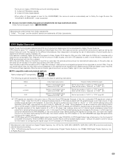
EVENT PARAMETER function example PS TONE DEFEAT ON PARAMETER setting PSTONE DEFEAT ON TONE DEFEAT OFF TONE DEFEAT ON/OFF PSTONE DEFEAT OFF SB:MTRX ON SURROUND BACK SP MODE set PSSB:MTRX ON SB:NON MTRX ---MTRX ON = SURR.EX ON = DSCRT ON PSSB:NON MTRX SB:OFF (at THX mode) (at FM band ( "EML" can change ONLY DOLBY PL2 mode. PSMODE : EMULATION TF UP TUNER Frequency UP/DOWN , direct change TFUP * DOWN TFDOWN * ****** (6 digits kHz at AM band (>050000 is AM.) TF105000 ****.** MHz at ES DSCRT mode) PSSB:OFF CINEMA EQ.ON CINEMA EQ. ON/OFF PSCINEMA EQ.ON CINEMA EQ...
EVENT PARAMETER function example PS TONE DEFEAT ON PARAMETER setting PSTONE DEFEAT ON TONE DEFEAT OFF TONE DEFEAT ON/OFF PSTONE DEFEAT OFF SB:MTRX ON SURROUND BACK SP MODE set PSSB:MTRX ON SB:NON MTRX ---MTRX ON = SURR.EX ON = DSCRT ON PSSB:NON MTRX SB:OFF (at THX mode) (at FM band ( "EML" can change ONLY DOLBY PL2 mode. PSMODE : EMULATION TF UP TUNER Frequency UP/DOWN , direct change TFUP * DOWN TFDOWN * ****** (6 digits kHz at AM band (>050000 is AM.) TF105000 ****.** MHz at ES DSCRT mode) PSSB:OFF CINEMA EQ.ON CINEMA EQ. ON/OFF PSCINEMA EQ.ON CINEMA EQ...


