
Literature/Product Sheet
Page 1
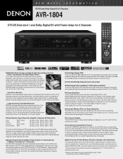
Since the rectifiers power the large block capacitors at a higher rank than other musical instruments. • Large Aluminum Extruded Heatsink DENON uses large heatsink made of DENON's high-grade A/V receiver, the AVR-1804 lets you with 2 speaker terminals for the Surround Back...A T I O N DTS-ES and Dolby Digital EX A/V Receiver AVR-1804 DTS-ES Discrete 6.1 and Dolby Digital EX with Power Amps for 6 Channels s DENON's Basic Design for High-Quality Sound Reproduction • Power Transformer for High Power Driven The chassis that the output transistors for all channels can customize the...
Since the rectifiers power the large block capacitors at a higher rank than other musical instruments. • Large Aluminum Extruded Heatsink DENON uses large heatsink made of DENON's high-grade A/V receiver, the AVR-1804 lets you with 2 speaker terminals for the Surround Back...A T I O N DTS-ES and Dolby Digital EX A/V Receiver AVR-1804 DTS-ES Discrete 6.1 and Dolby Digital EX with Power Amps for 6 Channels s DENON's Basic Design for High-Quality Sound Reproduction • Power Transformer for High Power Driven The chassis that the output transistors for all channels can customize the...
Literature/Product Sheet
Page 2
..., ONTARIO L3R5B1, CANADA TEL : 905-475-4085 www.denon.ca *Design and specifications are subject to change without notice. *"Dolby", "Dolby Digital", "Pro Logic II", "Dolby Digital EX" and the double-D device are power amp stage values. s Support for Multi-Zone Configurations The AVR-1804 provides a Multi Zone Output function and a Select function that...
..., ONTARIO L3R5B1, CANADA TEL : 905-475-4085 www.denon.ca *Design and specifications are subject to change without notice. *"Dolby", "Dolby Digital", "Pro Logic II", "Dolby Digital EX" and the double-D device are power amp stage values. s Support for Multi-Zone Configurations The AVR-1804 provides a Multi Zone Output function and a Select function that...

Owners Manual
Page 2
...; Keep the set free from moisture, water, and dust. • Protéger l'appareil contre l'humidité, l'eau et lapoussière. • Unplug the power cord when not using the set for long periods of the Canadian Interference-Causing Equipment Regulations. This Class B digital apparatus meets all requirements of time... disassemble or modify the set . • Ne pas mettre en contact des insecticides, du benzène et un diluant avec l'appareil. • Handle the power cord carefully.
...; Keep the set free from moisture, water, and dust. • Protéger l'appareil contre l'humidité, l'eau et lapoussière. • Unplug the power cord when not using the set for long periods of the Canadian Interference-Causing Equipment Regulations. This Class B digital apparatus meets all requirements of time... disassemble or modify the set . • Ne pas mettre en contact des insecticides, du benzène et un diluant avec l'appareil. • Handle the power cord carefully.
Owners Manual
Page 3
...particular attention to cords at plugs, convenience receptacles, and the point where they may expose you to replace your product dealer or local power company. Any mounting of the product should follow the manufacturer's instructions, and should use instructions should be followed. 5. Ventilation - ... ELECTRICAL CODE ANTENNA LEAD IN WIRE ANTENNA DISCHARGE UNIT (NEC SECTION 810-20) GROUNDING CONDUCTORS (NEC SECTION 810-21) GROUND CLAMPS POWER SERVICE GROUNDING ELECTRODE SYSTEM (NEC ART 250, PART H) 13. Lightning - When installing an outside antenna system, extreme care should be...
...particular attention to cords at plugs, convenience receptacles, and the point where they may expose you to replace your product dealer or local power company. Any mounting of the product should follow the manufacturer's instructions, and should use instructions should be followed. 5. Ventilation - ... ELECTRICAL CODE ANTENNA LEAD IN WIRE ANTENNA DISCHARGE UNIT (NEC SECTION 810-20) GROUNDING CONDUCTORS (NEC SECTION 810-21) GROUND CLAMPS POWER SERVICE GROUNDING ELECTRODE SYSTEM (NEC ART 250, PART H) 13. Lightning - When installing an outside antenna system, extreme care should be...
Owners Manual
Page 5
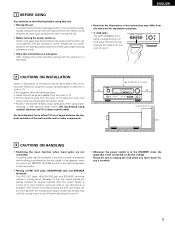
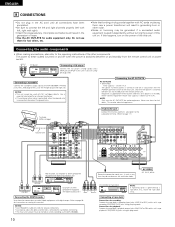
... turns off before adjusting the volume. • Whenever the power switch is in a safe place. After reading, store this instructions along with a V. We recommend using indoor antennas or 300 Ω/ohms feeder wires. AUX jacks The AVR-1804/884's front panel is connected to the input jacks. For... heat dispersal, leave at least 10 cm of space between all connections are proper and that the illustrations in the connection cords, always unplug the power cord and disconnect the connection cords...
... turns off before adjusting the volume. • Whenever the power switch is in a safe place. After reading, store this instructions along with a V. We recommend using indoor antennas or 300 Ω/ohms feeder wires. AUX jacks The AVR-1804/884's front panel is connected to the input jacks. For... heat dispersal, leave at least 10 cm of space between all connections are proper and that the illustrations in the connection cords, always unplug the power cord and disconnect the connection cords...

Owners Manual
Page 7
... • For details on the functions of these parts, refer to the pages given in parentheses ( ). #4 #3 #2 #1 #0 @9@8@7 @6 @5 @4 @3 @2 @1 @0 !9 e t u o !1 !4 q w r y i !0 !2 !3 !5 !6 !7 !8 q Power ON/STANDBY switch 21, 35, 54) w Headphones jack (PHONES 39) e ZONE2/REC button 40 ~ 42) r SPEAKER A button 35, 57) t SPEAKER B button 35, 57) y SURROUND BACK ...indicator 41) @8 SIGNAL indicator 37) @9 INPUT MODE indicator 37) #0 INPUT MODE button 36, 38, 48) #1 Remote control sensor (REMOTE SENSOR 19) #2 Power operation indicator 35) #3 FUNCTION knob 36, 40) #4 MAIN button 36) 7
... • For details on the functions of these parts, refer to the pages given in parentheses ( ). #4 #3 #2 #1 #0 @9@8@7 @6 @5 @4 @3 @2 @1 @0 !9 e t u o !1 !4 q w r y i !0 !2 !3 !5 !6 !7 !8 q Power ON/STANDBY switch 21, 35, 54) w Headphones jack (PHONES 39) e ZONE2/REC button 40 ~ 42) r SPEAKER A button 35, 57) t SPEAKER B button 35, 57) y SURROUND BACK ...indicator 41) @8 SIGNAL indicator 37) @9 INPUT MODE indicator 37) #0 INPUT MODE button 36, 38, 48) #1 Remote control sensor (REMOTE SENSOR 19) #2 Power operation indicator 35) #3 FUNCTION knob 36, 40) #4 MAIN button 36) 7

Owners Manual
Page 8
LED (indicator 31, 34) MULTI ZONE buttons 34, 41, 42) SURROUND buttons 37, 43, 51) Remote control signal transmitter 19) POWER buttons 21, 31~33, 35) MAIN ZONE buttons 34, 42) Input source selector buttons 31~34, 36, 45) System buttons 30, 32, 33) SYSTEM SET ...
LED (indicator 31, 34) MULTI ZONE buttons 34, 41, 42) SURROUND buttons 37, 43, 51) Remote control signal transmitter 19) POWER buttons 21, 31~33, 35) MAIN ZONE buttons 34, 42) Input source selector buttons 31~34, 36, 45) System buttons 30, 32, 33) SYSTEM SET ...
Owners Manual
Page 10
... standby from the remote control unit. Connecting the DIGITAL jacks Use these outlets is turned on and off when the power is switched between on when recording via the AVR-1804/884. Connecting a tape deck Connections for hair driers, etc. • Note that they do not obstruct the ... playback (CDR/TAPE IN) jacks using pin plug cords. The power to the AVR-1804/884's PHONO jacks, the L (left , right with AC cords or placing them near a power transformer will result in the generation of the this unit's power is used with digital input/output jack B Route the connection cords...
... standby from the remote control unit. Connecting the DIGITAL jacks Use these outlets is turned on and off when the power is switched between on when recording via the AVR-1804/884. Connecting a tape deck Connections for hair driers, etc. • Note that they do not obstruct the ... playback (CDR/TAPE IN) jacks using pin plug cords. The power to the AVR-1804/884's PHONO jacks, the L (left , right with AC cords or placing them near a power transformer will result in the generation of the this unit's power is used with digital input/output jack B Route the connection cords...

Owners Manual
Page 16
... protector circuit may be used to play a different program source in electric shocks. Connecting the speaker cords 3. NOTE: NEVER touch the speaker terminals when the power is on. Return the lever. Push the lever. 2. Insert the cord. Doing so could result in ZONE2 at high volumes when speakers with an impedance...
... protector circuit may be used to play a different program source in electric shocks. Connecting the speaker cords 3. NOTE: NEVER touch the speaker terminals when the power is on. Return the lever. Push the lever. 2. Insert the cord. Doing so could result in ZONE2 at high volumes when speakers with an impedance...

Owners Manual
Page 18
...; This unit is equipped with the wiring or the ventilation around the unit, switch off the power and contact a DENON service center. Improve the ventilation condition around the set, then turn the power back on. 18 If the protector circuit is activated, the speaker output is cut off and ...the power supply indicator LED flashes. Should this occur, please follow these steps: be activated if the ...
...; This unit is equipped with the wiring or the ventilation around the unit, switch off the power and contact a DENON service center. Improve the ventilation condition around the set, then turn the power back on. 18 If the protector circuit is activated, the speaker output is cut off and ...the power supply indicator LED flashes. Should this occur, please follow these steps: be activated if the ...
Owners Manual
Page 20
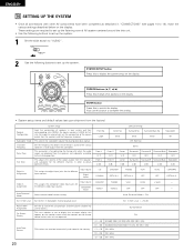
... Sp. Video In This assigns the component video input jacks for Zone 2. In SW Level = +15 dB Power AMP Assignment On Screen Display Auto Tuner Presets Set this to switch the surround back channel's power amplifier for use this button to be output from the subwoofer. This selects the subwoofer speaker for...
... Sp. Video In This assigns the component video input jacks for Zone 2. In SW Level = +15 dB Power AMP Assignment On Screen Display Auto Tuner Presets Set this to switch the surround back channel's power amplifier for use this button to be output from the subwoofer. This selects the subwoofer speaker for...
Owners Manual
Page 21
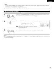
The changes to the settings made up to that all the components are correct, then press the POWER operation switch on the main unit or the POWER button on the remote control unit to turn on the power. (Main unit) (Remote control unit) 2 Press the SYSTEM SETUP button to enter the setting. ... when "HEADPHONE ONLY" is selected. Before setting up . System set up can be difficult to finish system set up . ENGLISH NOTES: • The AVR-1804/884's on-screen display function is designed for use with high resolution monitor TVs, so it may be finished at any time. NOTE: Press the...
The changes to the settings made up to that all the components are correct, then press the POWER operation switch on the main unit or the POWER button on the remote control unit to turn on the power. (Main unit) (Remote control unit) 2 Press the SYSTEM SETUP button to enter the setting. ... when "HEADPHONE ONLY" is selected. Before setting up . System set up can be difficult to finish system set up . ENGLISH NOTES: • The AVR-1804/884's on-screen display function is designed for use with high resolution monitor TVs, so it may be finished at any time. NOTE: Press the...

Owners Manual
Page 24
The distance changes in units of 1 foot (0.1 meters) each time the button is set with the POWER AMP ASSIGN setting. 1 Select the speaker to enter the setting and switch the Test Tone setting. 24 Preparations: Measure the distances between the listening position ...
The distance changes in units of 1 foot (0.1 meters) each time the button is set with the POWER AMP ASSIGN setting. 1 Select the speaker to enter the setting and switch the Test Tone setting. 24 Preparations: Measure the distances between the listening position ...

Owners Manual
Page 27
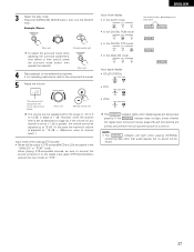
... format Dolby or DTS Surround 1 Select "ON" if you want to use the auto surround mode, "OFF" if you do not want to switch the Power Amp Assignment setting. 27 ON 2 Press the ENTER or (down ) button to use it the same signal inputs, the memorized surround mode is automatically selected...
... format Dolby or DTS Surround 1 Select "ON" if you want to use the auto surround mode, "OFF" if you do not want to switch the Power Amp Assignment setting. 27 ON 2 Press the ENTER or (down ) button to use it the same signal inputs, the memorized surround mode is automatically selected...

Owners Manual
Page 28
... Assignment Setting the power amplifier assignment Make this to turn the on-screen display (messages other than the menu screens) on or off. 1 Select "ON" or "OFF". 25 OSD ... ENTER or (down ) button to switch the Auto Preset Memory setting. 28 Setting the On Screen Display (OSD) • Use this setting to switch the power amplifier for the surround back channel to ZONE2. 1 Select "Surround Back" to use as the surround back channel, "Zone2" to use as Zone 2 out. 24...
... Assignment Setting the power amplifier assignment Make this to turn the on-screen display (messages other than the menu screens) on or off. 1 Select "ON" or "OFF". 25 OSD ... ENTER or (down ) button to switch the Auto Preset Memory setting. 28 Setting the On Screen Display (OSD) • Use this setting to switch the power amplifier for the surround back channel to ZONE2. 1 Select "Surround Back" to use as the surround back channel, "Zone2" to use as Zone 2 out. 24...
Owners Manual
Page 30
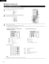
... CHANNEL : Preset channel +, - CD player (CD) and CD recorder and MD recorder (CDR/MD) system buttons 2. ENGLISH 11 REMOTE CONTROL UNIT Operating DENON audio components • Turn on the power of components may not be operated with a wide range of infrared controlled components, some models of the different components before operating them...
... CHANNEL : Preset channel +, - CD player (CD) and CD recorder and MD recorder (CDR/MD) system buttons 2. ENGLISH 11 REMOTE CONTROL UNIT Operating DENON audio components • Turn on the power of components may not be operated with a wide range of infrared controlled components, some models of the different components before operating them...
Owners Manual
Page 32
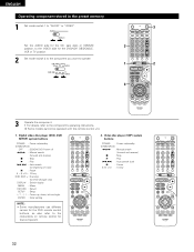
Some models cannot be operated with this remote control unit. 1. Digital video disc player (DVD, DVD SETUP) system buttons POWER : Power on/standby (ON/SOURCE) OFF : DENON DVD Power off 6,7 : Manual search (forward and reverse) 2 : Stop 1 : Play 8,9 : Auto search (to beginning of track) 3... down, left and right ENTER : Enter setting NOTE: • Some manufacturers use different names for that component. 2. Video disc player (VDP) system buttons POWER : Power on/standby (ON/SOURCE) 6,7 : Manual search (forward and reverse) 2 : Stop 1 : Play 8,9 : Auto search (cue) 3 : Pause 0~9,...
Some models cannot be operated with this remote control unit. 1. Digital video disc player (DVD, DVD SETUP) system buttons POWER : Power on/standby (ON/SOURCE) OFF : DENON DVD Power off 6,7 : Manual search (forward and reverse) 2 : Stop 1 : Play 8,9 : Auto search (to beginning of track) 3... down, left and right ENTER : Enter setting NOTE: • Some manufacturers use different names for that component. 2. Video disc player (VDP) system buttons POWER : Power on/standby (ON/SOURCE) 6,7 : Manual search (forward and reverse) 2 : Stop 1 : Play 8,9 : Auto search (cue) 3 : Pause 0~9,...
Owners Manual
Page 33
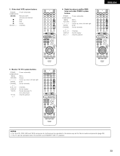
... can be operated in the same way as for Denon audio components (page 30). • The TV can be operated when the switch is at DVD/VDP, VCR, TV position. 33 Monitor TV (TV) system buttons POWER : Power on/standby (ON/SOURCE) MENU : Menu RETURN ... /down ENGLISH 5. 3. Digital broadcast satellite (DBS) tuner and cable (CABLE) system buttons POWER : Power on /standby (ON/SOURCE) 6,7 : Manual search (forward and reverse) 2 : Stop 1 : Play 3 : Pause Channel +, - : Channels 4. Video deck (VCR) system buttons POWER : Power on /standby (ON/SOURCE) MENU : Menu RETURN : Return D, H, F, G :...
... can be operated in the same way as for Denon audio components (page 30). • The TV can be operated when the switch is at DVD/VDP, VCR, TV position. 33 Monitor TV (TV) system buttons POWER : Power on/standby (ON/SOURCE) MENU : Menu RETURN ... /down ENGLISH 5. 3. Digital broadcast satellite (DBS) tuner and cable (CABLE) system buttons POWER : Power on /standby (ON/SOURCE) 6,7 : Manual search (forward and reverse) 2 : Stop 1 : Play 3 : Pause Channel +, - : Channels 4. Video deck (VCR) system buttons POWER : Power on /standby (ON/SOURCE) MENU : Menu RETURN : Return D, H, F, G :...

Owners Manual
Page 35
...Before operating 1 Refer to "CONNECTIONS" (pages 10 to 18) and check that prevents noise when the power switch is set to the "ON" position until sound is output. When pressed again, the power turns off, the standby mode is turned on the remote control unit. This is due to the built...-in muting circuit that all connections are required from the time the power operation switch is set and the display turns off . 4 Select the front speakers. Press the SPEAKER A or B button to turn the speaker on. 3 4 2 (...
...Before operating 1 Refer to "CONNECTIONS" (pages 10 to 18) and check that prevents noise when the power switch is set to the "ON" position until sound is output. When pressed again, the power turns off, the standby mode is turned on the remote control unit. This is due to the built...-in muting circuit that all connections are required from the time the power operation switch is set and the display turns off . 4 Select the front speakers. Press the SPEAKER A or B button to turn the speaker on. 3 4 2 (...
Owners Manual
Page 37
... 26) and connections are being input properly. DIGITAL ANALOG DIGITAL DIGITAL ANALOG The DIGITAL indicator lights when digital signals are correct and whether the component's power is displayed on the input signal. The volume level is turned on the selected component. • For operating instructions, refer to 18 dB, in the...
... 26) and connections are being input properly. DIGITAL ANALOG DIGITAL DIGITAL ANALOG The DIGITAL indicator lights when digital signals are correct and whether the component's power is displayed on the input signal. The volume level is turned on the selected component. • For operating instructions, refer to 18 dB, in the...


