
Literature/Product Sheet
Page 2
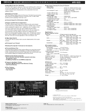
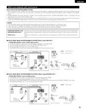
... for Multi Zone Configurations The AVR-1803 provides a Multi Zone Output function and a Select function that source. ■ Multi-function Remote Controller • Self-illuminated GLO-KEY Remote Controller with terminal cover. (*1) Note on Movie mode: On DENON A/V receivers, this Movie mode..., as well as "MODE CINEMA". *Design and specifications are subject to the main speaker system. ■ Multi Source Function The AVR-1803 provides a Multi OUT terminal. DENON, LTD. 3-16-11, YUSHIMA, BUNKYO-KU, TOKYO 113-0034, JAPAN 13010802 A Input FRONT L/R, CENTER, SURROUND L/R, SUBWOOFER 4...
... for Multi Zone Configurations The AVR-1803 provides a Multi Zone Output function and a Select function that source. ■ Multi-function Remote Controller • Self-illuminated GLO-KEY Remote Controller with terminal cover. (*1) Note on Movie mode: On DENON A/V receivers, this Movie mode..., as well as "MODE CINEMA". *Design and specifications are subject to the main speaker system. ■ Multi Source Function The AVR-1803 provides a Multi OUT terminal. DENON, LTD. 3-16-11, YUSHIMA, BUNKYO-KU, TOKYO 113-0034, JAPAN 13010802 A Input FRONT L/R, CENTER, SURROUND L/R, SUBWOOFER 4...
Owners Manual
Page 4
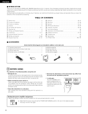
...on Handling 5 v Features ...5 b Part Names and Functions 6, 7 n Read this setting to switch the power amplifier for choosing the DENON AVR-1803/883 Digital Surround A / V receiver. Always set the power switch to the standby position before using this manual before proceeding. AUX jacks.... Note that there are included in addition to the main unit: q Operating instructions 1 w Warranty (for explanation purposes. • V. Using the Remote Control Unit 18 ⁄0 Setting up the Speaker Systems 8 , Connections 9~17 . After reading, store this instructions in the AC main again. 4...
...on Handling 5 v Features ...5 b Part Names and Functions 6, 7 n Read this setting to switch the power amplifier for choosing the DENON AVR-1803/883 Digital Surround A / V receiver. Always set the power switch to the standby position before using this manual before proceeding. AUX jacks.... Note that there are included in addition to the main unit: q Operating instructions 1 w Warranty (for explanation purposes. • V. Using the Remote Control Unit 18 ⁄0 Setting up the Speaker Systems 8 , Connections 9~17 . After reading, store this instructions in the AC main again. 4...

Owners Manual
Page 6
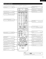
... 34) @4 Display @5 Preset station select buttons 53, 55) @6 BAND button 54) @7 INPUT MODE indicator 34) @8 SIGNAL indicator 34) @9 INPUT MODE button 33, 35, 45) #0 Remote control sensor (REMOTE SENSOR 18) #1 Power operation indicator 32) #2 FUNCTION knob 33, 37, 42, 43, 45, 54) #3 MAIN button 33) 6 IN button 33, 35) o DOLBY/DTS SURROUND...
... 34) @4 Display @5 Preset station select buttons 53, 55) @6 BAND button 54) @7 INPUT MODE indicator 34) @8 SIGNAL indicator 34) @9 INPUT MODE button 33, 35, 45) #0 Remote control sensor (REMOTE SENSOR 18) #1 Power operation indicator 32) #2 FUNCTION knob 33, 37, 42, 43, 45, 54) #3 MAIN button 33) 6 IN button 33, 35) o DOLBY/DTS SURROUND...
Owners Manual
Page 7
LED (indicator 28, 31) MULTI ZONE buttons 31, 38) SURROUND buttons 34, 40, 42, 44, 45, 49) ENGLISH Remote control signal transmitter 18) POWER buttons 20, 28~30, 32) MAIN ZONE buttons 31, 38) Input source selector buttons 28~31, 33, 42, 43, 45) ...~26, 29, 30, 41, 43) SURROUND BACK/RETURN button 29, 30, 45) DIMMER button 36) NOTE: • The shaded buttons do not function with the AVR-1803/883. (Nothing happens when they are pressed.) 7 Remote control unit • For details on the functions of these parts, refer to the pages given in parentheses ( ).
LED (indicator 28, 31) MULTI ZONE buttons 31, 38) SURROUND buttons 34, 40, 42, 44, 45, 49) ENGLISH Remote control signal transmitter 18) POWER buttons 20, 28~30, 32) MAIN ZONE buttons 31, 38) Input source selector buttons 28~31, 33, 42, 43, 45) ...~26, 29, 30, 41, 43) SURROUND BACK/RETURN button 29, 30, 45) DIMMER button 36) NOTE: • The shaded buttons do not function with the AVR-1803/883. (Nothing happens when they are pressed.) 7 Remote control unit • For details on the functions of these parts, refer to the pages given in parentheses ( ).
Owners Manual
Page 8
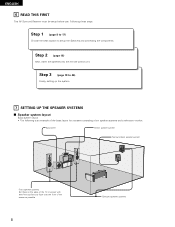
... as possible. 8 Surround speaker systems Step 3 (page 19 to setup the Speakers and connecting the components. Step 2 (page 18) Next, insert the batteries into the remote control unit. Step 1 (page 8 to 17) Choose the best location to 26) Finally, setting up the system. 7 SETTING UP THE SPEAKER SYSTEMS 2 Speaker system layout...
... as possible. 8 Surround speaker systems Step 3 (page 19 to setup the Speakers and connecting the components. Step 2 (page 18) Next, insert the batteries into the remote control unit. Step 1 (page 8 to 17) Choose the best location to 26) Finally, setting up the system. 7 SETTING UP THE SPEAKER SYSTEMS 2 Speaker system layout...
Owners Manual
Page 9
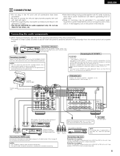
...TVs or other noise. • Noise or humming may be used independently without turning the power of the this unit on and standby from the remote control unit or power switch. Connections for recording: Connect the tape deck's recording input jacks (LINE IN or REC) to this unit's CD... generating hum or other electrical appliances. If this happens, turn on the power of this unit. Connecting a turntable Connect the turntable's output cord to the AVR-1803/883's PHONO jacks, the L (left) plug to the L jack, the R (right) plug to connect the left and right channels properly (left with ...
...TVs or other noise. • Noise or humming may be used independently without turning the power of the this unit on and standby from the remote control unit or power switch. Connections for recording: Connect the tape deck's recording input jacks (LINE IN or REC) to this unit's CD... generating hum or other electrical appliances. If this happens, turn on the power of this unit. Connecting a turntable Connect the turntable's output cord to the AVR-1803/883's PHONO jacks, the L (left) plug to the L jack, the R (right) plug to connect the left and right channels properly (left with ...
Owners Manual
Page 18
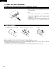
.... • Be sure the polarities are correct. (See the illustration inside the battery compartment.) • Remove the batteries if the remote control transmitter will not be used from a straight distance of approximately 23 feet/7 meters, but this distance will shorten or operation will ...when the time comes. • Even if less than a year has passed, replace the batteries with clothing, etc. ENGLISH 9 USING THE REMOTE CONTROL UNIT Following the procedure outlined below, insert the batteries before installing new batteries. • Have replacement batteries on hand so that the ...
.... • Be sure the polarities are correct. (See the illustration inside the battery compartment.) • Remove the batteries if the remote control transmitter will not be used from a straight distance of approximately 23 feet/7 meters, but this distance will shorten or operation will ...when the time comes. • Even if less than a year has passed, replace the batteries with clothing, etc. ENGLISH 9 USING THE REMOTE CONTROL UNIT Following the procedure outlined below, insert the batteries before installing new batteries. • Have replacement batteries on hand so that the ...

Owners Manual
Page 20
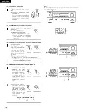
...1 Check that point are correct, then press the POWER operation switch on the main unit or the POWER button on the remote control unit to turn on the power. (Main unit) (Remote control unit) 2 Press the SYSTEM SETUP button to enter the setting. *SYSTEM SET UP NOTE: Please make sure the ..."AUDIO" position of the slide switch on the remote control unit. 3 Press the ENTER or (down) button to switch to the speaker configuration set up. System set up can be selected for the surround...
...1 Check that point are correct, then press the POWER operation switch on the main unit or the POWER button on the remote control unit to turn on the power. (Main unit) (Remote control unit) 2 Press the SYSTEM SETUP button to enter the setting. *SYSTEM SET UP NOTE: Please make sure the ..."AUDIO" position of the slide switch on the remote control unit. 3 Press the ENTER or (down) button to switch to the speaker configuration set up. System set up can be selected for the surround...
Owners Manual
Page 27
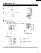
... search (forward and reverse) : Stop : Play : Auto search (cue) : Pause : Switch discs (for the component to be operated with this remote control is at "AUDIO" position. 27 11 REMOTE CONTROL UNIT Operating DENON audio components • Turn on the power of components may not be operated. (CD, CDR/MD or Tape deck) 1 3 ENGLISH...
... search (forward and reverse) : Stop : Play : Auto search (cue) : Pause : Switch discs (for the component to be operated with this remote control is at "AUDIO" position. 27 11 REMOTE CONTROL UNIT Operating DENON audio components • Turn on the power of components may not be operated. (CD, CDR/MD or Tape deck) 1 3 ENGLISH...

Owners Manual
Page 28
...for some models, even if they are of makes listed on the List of Preset Codes (pages 126~130). To avoid accidental operation, cover the remote control unit's transmitting window while setting the preset memory. • Depending on the model and year of manufacture, this function cannot be used to ...be operated by registering the manufacturer of the component as follows upon shipment from the factory and after resetting: TV, VCR HITACHI CD, TAPE DENON CDR/MD DENON (CDR) DVD/VDP DENON (DVD) DBS/CABLE ABC (CABLE) 28 The preset codes are emitted while setting the preset memory.
...for some models, even if they are of makes listed on the List of Preset Codes (pages 126~130). To avoid accidental operation, cover the remote control unit's transmitting window while setting the preset memory. • Depending on the model and year of manufacture, this function cannot be used to ...be operated by registering the manufacturer of the component as follows upon shipment from the factory and after resetting: TV, VCR HITACHI CD, TAPE DENON CDR/MD DENON (CDR) DVD/VDP DENON (DVD) DBS/CABLE ABC (CABLE) 28 The preset codes are emitted while setting the preset memory.
Owners Manual
Page 29
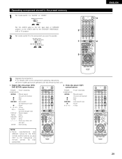
... 0~9, +10 : 10 key NOTE: • Some manufacturers use different names for that component. 29 Some models cannot be operated with this remote control unit. 1. Digital video disc player (DVD, DVD SETUP) system buttons 2. Set the AUDIO side for the CD, tape deck or CDR... component you want to operate. 1 3 ENGLISH 3 2 3 Operate the component. • For details, refer to the instructions on remote control for the DVD remote control buttons, so also refer to the component's operating instructions. Operating component stored in the preset memory 1 Set mode switch 1 to ...
... 0~9, +10 : 10 key NOTE: • Some manufacturers use different names for that component. 29 Some models cannot be operated with this remote control unit. 1. Digital video disc player (DVD, DVD SETUP) system buttons 2. Set the AUDIO side for the CD, tape deck or CDR... component you want to operate. 1 3 ENGLISH 3 2 3 Operate the component. • For details, refer to the instructions on remote control for the DVD remote control buttons, so also refer to the component's operating instructions. Operating component stored in the preset memory 1 Set mode switch 1 to ...

Owners Manual
Page 32
... the power operation switch is set and the display turns off. 2 Several seconds are correct. 2 Set the remote control unit's slide switch to the AUDIO position. (only when operating with the remote control unit) 3 Turn on the power. ENGLISH 12 OPERATION Before operating 1 Refer to "CONNECTIONS" (pages 9... approximately 1 second. Press the ON/STANDBY button on the main unit or ON/SOURCE button on the remote control unit to turn on the 3 power. 3 ON/STANDBY Light (Main unit) (Remote control unit) • ON/STANDBY When the button is pressed, the power turns on and off ,...
... the power operation switch is set and the display turns off. 2 Several seconds are correct. 2 Set the remote control unit's slide switch to the AUDIO position. (only when operating with the remote control unit) 3 Turn on the power. ENGLISH 12 OPERATION Before operating 1 Refer to "CONNECTIONS" (pages 9... approximately 1 second. Press the ON/STANDBY button on the main unit or ON/SOURCE button on the remote control unit to turn on the 3 power. 3 ON/STANDBY Light (Main unit) (Remote control unit) • ON/STANDBY When the button is pressed, the power turns on and off ,...
Owners Manual
Page 33
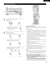
...signals being input, the analog input jacks are selected. Note that noise will be selected for the selected input source are played in the AVR-1803/883's surround decoder is selected automatically upon playback. Notes on playing a source encoded with DTS • Noise may be generated when ... input jacks are played without passing through the surround circuitry. If so, play Dolby Digital signals. AUTO PCM DTS (Main unit) (Remote control unit) 2 Input mode selection function Different input modes can be output when CDs or LDs recorded in DTS format are detected and...
...signals being input, the analog input jacks are selected. Note that noise will be selected for the selected input source are played in the AVR-1803/883's surround decoder is selected automatically upon playback. Notes on playing a source encoded with DTS • Noise may be generated when ... input jacks are played without passing through the surround circuitry. If so, play Dolby Digital signals. AUTO PCM DTS (Main unit) (Remote control unit) 2 Input mode selection function Different input modes can be output when CDs or LDs recorded in DTS format are detected and...

Owners Manual
Page 34
...sources • Noise will be adjusted within the range of these lights, depending on the master volume level display. (Main unit) (Remote control unit) The volume can be output if DTS-compatible CDs or LDs are correct and whether the component's power is displayed on...To select the surround mode while adjusting the surround parameters, channel volume or tone control, press the surround mode button then operate the selector. (Remote control unit) (Main unit) 4 Start playback on . When playing DTS-compatible sources, be heard. 34 DIGITAL ANALOG DIGITAL DIGITAL ANALOG Input ...
...sources • Noise will be adjusted within the range of these lights, depending on the master volume level display. (Main unit) (Remote control unit) The volume can be output if DTS-compatible CDs or LDs are correct and whether the component's power is displayed on...To select the surround mode while adjusting the surround parameters, channel volume or tone control, press the surround mode button then operate the selector. (Remote control unit) (Main unit) 4 Start playback on . When playing DTS-compatible sources, be heard. 34 DIGITAL ANALOG DIGITAL DIGITAL ANALOG Input ...

Owners Manual
Page 35
.... IN) setting, press the INPUT MODE (AUTO, PCM, DTS) or ANALOG button to switch to the desired input mode. (See page 33.) (Main unit) (Remote control unit) • When the input mode is output to the external input (EXT. IN), the play mode (DIRECT, STEREO, DOLBY/DTS SURROUND, 5CH/6CH...to which the video signal is selected, the input signals connected to EXT. Press the EXT. IN to switch the external input. (Main unit) (Remote control unit) Once this mode. After starting playback [1] Adjusting the sound quality (tone) The tone control function will not work in steps of the EXT...
.... IN) setting, press the INPUT MODE (AUTO, PCM, DTS) or ANALOG button to switch to the desired input mode. (See page 33.) (Main unit) (Remote control unit) • When the input mode is output to the external input (EXT. IN), the play mode (DIRECT, STEREO, DOLBY/DTS SURROUND, 5CH/6CH...to which the video signal is selected, the input signals connected to EXT. Press the EXT. IN to switch the external input. (Main unit) (Remote control unit) Once this mode. After starting playback [1] Adjusting the sound quality (tone) The tone control function will not work in steps of the EXT...
Owners Manual
Page 36
...dimmer function • Use this switch to check the unit's operating status (Main unit) (Remote control unit) 2 while playing a source by pressing the main (Main unit) (Remote control unit) unit's DIMMER button repeatedly. The display brightness changes in four steps (bright, medium..., dim and off when headphones are also displayed on (Main unit) (Remote control unit) 1 the display. BRIGHT MEDIUM DIM OFF 1 1 21 36 The pre-out output (including the speaker output) is ...
...dimmer function • Use this switch to check the unit's operating status (Main unit) (Remote control unit) 2 while playing a source by pressing the main (Main unit) (Remote control unit) unit's DIMMER button repeatedly. The display brightness changes in four steps (bright, medium..., dim and off when headphones are also displayed on (Main unit) (Remote control unit) 1 the display. BRIGHT MEDIUM DIM OFF 1 1 21 36 The pre-out output (including the speaker output) is ...

Owners Manual
Page 38
... zone output can be turned on the remote control unit. buttons on and off with the "MAIN ON/OFF" button. 5 4 (Remote control unit) DEFAULT SETTING (ZONE2 VOLUME LEVEL) : - - - buttons on the remote control unit. (This is set to "AUDIO" and "ZONE2". 2 (Remote control unit) 2 Press the ZONE2 "...dB (MINIMUM) 5 When the ZONE2 SOURCE function is only possible when the main unit in the ZONE2 mode.) (Remote control unit) 38 Press the ZONE2 "OFF" button. (Remote control unit) 1 3 Press the input source button • The ZONE2 source switches directly. 4 The output level...
... zone output can be turned on the remote control unit. buttons on and off with the "MAIN ON/OFF" button. 5 4 (Remote control unit) DEFAULT SETTING (ZONE2 VOLUME LEVEL) : - - - buttons on the remote control unit. (This is set to "AUDIO" and "ZONE2". 2 (Remote control unit) 2 Press the ZONE2 "...dB (MINIMUM) 5 When the ZONE2 SOURCE function is only possible when the main unit in the ZONE2 mode.) (Remote control unit) 38 Press the ZONE2 "OFF" button. (Remote control unit) 1 3 Press the input source button • The ZONE2 source switches directly. 4 The output level...
Owners Manual
Page 39
... separately sold separately room-to-room remote control unit (DENON RC-616, 617 or 618) is wired and connected between the main zone and zone2, the remote-controllable devices in the main zone can be adjusted with ZONE2 mode RC-617 AVR-1803/883 FL C FR SW SL RC-616 REMOTE CONTROL UNIT SR (Main unit...
... separately sold separately room-to-room remote control unit (DENON RC-616, 617 or 618) is wired and connected between the main zone and zone2, the remote-controllable devices in the main zone can be adjusted with ZONE2 mode RC-617 AVR-1803/883 FL C FR SW SL RC-616 REMOTE CONTROL UNIT SR (Main unit...

Owners Manual
Page 40
...is only effective in the memory of the slide switch on the remote control unit. 3 After completing the adjustment, press the TEST TONE button again. (Remote control unit) 1 1 2 2 2, 3 40 The adjusted playback levels for all the speakers. (Remote control unit) (Remote control unit) NOTE: Please make sure the "AUDIO" position ... from each surround modes. 1 Set the DOLBY/DTS SURROUND (Dolby Pro Logic II or Dolby Digital or DTS) modes. (Main unit) (Remote control unit) 2 Press the TEST TONE button. Test tones are automatically stored in the DOLBY/DTS SURROUND modes.
...is only effective in the memory of the slide switch on the remote control unit. 3 After completing the adjustment, press the TEST TONE button again. (Remote control unit) 1 1 2 2 2, 3 40 The adjusted playback levels for all the speakers. (Remote control unit) (Remote control unit) NOTE: Please make sure the "AUDIO" position ... from each surround modes. 1 Set the DOLBY/DTS SURROUND (Dolby Pro Logic II or Dolby Digital or DTS) modes. (Main unit) (Remote control unit) 2 Press the TEST TONE button. Test tones are automatically stored in the DOLBY/DTS SURROUND modes.

Owners Manual
Page 41
... SL "SB" appears only when "POWER AMP ASSIGN" switch is selected with the CH VOL buttons on the main unit. (Remote control unit) Default setting of +12 to adjust. (Main unit) (Remote control unit) The channel switches as (described) below each time the button is pressed. OFF ´ -12 dB ´ 12... dB 21 2 1 2 41 NOTE: Please make sure the "AUDIO" position of the slide switch on the remote control unit. 2 Adjust the level of the selected speaker. (Main unit) Only adjustable when the channel is SURR.
... SL "SB" appears only when "POWER AMP ASSIGN" switch is selected with the CH VOL buttons on the main unit. (Remote control unit) Default setting of +12 to adjust. (Main unit) (Remote control unit) The channel switches as (described) below each time the button is pressed. OFF ´ -12 dB ´ 12... dB 21 2 1 2 41 NOTE: Please make sure the "AUDIO" position of the slide switch on the remote control unit. 2 Adjust the level of the selected speaker. (Main unit) Only adjustable when the channel is SURR.


