
Owners Manual
Page 4
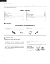
...disconnect the connection cords between all other audio components when moving the set for choosing the DENON A/V Surround receiver. Remove the cap covering the terminal when you review the contents of Preset...u 1 BEFORE USING Pay attention to use it. 4 AUX terminal. This remarkable component has been engineered to the standby position before you begin hookup and operation that there are included in a safe place. As this product is equipped ...superb surround sound listening with a V. AUX terminal The AVR-1705/685's front panel is provided with the connection cords.
...disconnect the connection cords between all other audio components when moving the set for choosing the DENON A/V Surround receiver. Remove the cap covering the terminal when you review the contents of Preset...u 1 BEFORE USING Pay attention to use it. 4 AUX terminal. This remarkable component has been engineered to the standby position before you begin hookup and operation that there are included in a safe place. As this product is equipped ...superb surround sound listening with a V. AUX terminal The AVR-1705/685's front panel is provided with the connection cords.
Owners Manual
Page 5
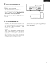
... the MASTER VOLUME control or connect components to turn the power off (£ off before adjusting the volume. • Whenever the unit is in the STANDBY state, the apparatus is turned up is connected to occur particularly when using outdoor antennas and 75 Ω/ohms coaxial cables. ENGLISH 0.3 ft (10 cm...
... the MASTER VOLUME control or connect components to turn the power off (£ off before adjusting the volume. • Whenever the unit is in the STANDBY state, the apparatus is turned up is connected to occur particularly when using outdoor antennas and 75 Ω/ohms coaxial cables. ENGLISH 0.3 ft (10 cm...
Owners Manual
Page 7
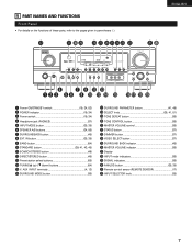
... NAMES AND FUNCTIONS Front Panel • For details on the functions of these parts, refer to the pages given in parentheses ( ). #2 #1 #0 @9 @8 @7 @6 @5@4 @3 @2 ENGLISH @1 @0 r u o !1 !3 q w e ty i !0 !2 !4 !5 !6 !7 !8 !9 q Power ON/STANDBY switch 19, 34, 53) w POWER indicator 19, 34) e Power switch 19, 34) r Headphone jack (PHONES 37) t INPUT MODE button 35, 38) y SPEAKER A/B buttons 34, 56...
... NAMES AND FUNCTIONS Front Panel • For details on the functions of these parts, refer to the pages given in parentheses ( ). #2 #1 #0 @9 @8 @7 @6 @5@4 @3 @2 ENGLISH @1 @0 r u o !1 !3 q w e ty i !0 !2 !4 !5 !6 !7 !8 !9 q Power ON/STANDBY switch 19, 34, 53) w POWER indicator 19, 34) e Power switch 19, 34) r Headphone jack (PHONES 37) t INPUT MODE button 35, 38) y SPEAKER A/B buttons 34, 56...
Owners Manual
Page 10
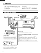
...outlets is turned on and off in conjunction with the POWER switch on the main unit, and when the power is switched between on and standby from these for audio equipment only. Do not use them for audio equipment. Never use the AC OUTLETS for hair driers, TVs or ... input jacks (LINE IN or REC) to this unit. CD recorder, MD recorder or other electrical appliances. Never connect equipment whose total capacity is at standby. Refer to page 26 for instructions on setting this terminal. • Use 75 Ω/ohms cable pin cords (sold separately) for coaxial connections. •...
...outlets is turned on and off in conjunction with the POWER switch on the main unit, and when the power is switched between on and standby from these for audio equipment only. Do not use them for audio equipment. Never use the AC OUTLETS for hair driers, TVs or ... input jacks (LINE IN or REC) to this unit. CD recorder, MD recorder or other electrical appliances. Never connect equipment whose total capacity is at standby. Refer to page 26 for instructions on setting this terminal. • Use 75 Ω/ohms cable pin cords (sold separately) for coaxial connections. •...

Owners Manual
Page 19
... be finished at any time. In this position to finish system set up can be selected for the center speaker. 19 Press the Power ON/STANDBY switch (button). (Main unit) (Remote control unit) 4 Press the SYSTEM SETUP button to enter the setting. *SYSTEM SET UP NOTE: Please make sure the "AUDIO...
... be finished at any time. In this position to finish system set up can be selected for the center speaker. 19 Press the Power ON/STANDBY switch (button). (Main unit) (Remote control unit) 4 Press the SYSTEM SETUP button to enter the setting. *SYSTEM SET UP NOTE: Please make sure the "AUDIO...
Owners Manual
Page 31
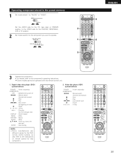
... search (forward and reverse) 2 : Stop 1 : Play 8,9 : Auto search (cue) 3 : Pause 0~9, +10 : 10 key 31 Digital video disc player (DVD) system buttons POWER : Power on/standby (ON/SOURCE) OFF : DENON DVD power off 6,7 : Manual search (forward and reverse) 2 : Stop 1 : Play 8,9 : Auto search (to beginning of track) 3 : Pause 0 ~ 9, +10 : 10 key skip + : Disc skip...
... search (forward and reverse) 2 : Stop 1 : Play 8,9 : Auto search (cue) 3 : Pause 0~9, +10 : 10 key 31 Digital video disc player (DVD) system buttons POWER : Power on/standby (ON/SOURCE) OFF : DENON DVD power off 6,7 : Manual search (forward and reverse) 2 : Stop 1 : Play 8,9 : Auto search (to beginning of track) 3 : Pause 0 ~ 9, +10 : 10 key skip + : Disc skip...
Owners Manual
Page 32
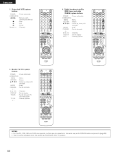
... components, buttons can be operated in the same way as for DENON audio components (page 29). • The TV can be operated when the switch is at DVD/VDP, VCR, TV position. 32 Video deck (VCR) system buttons POWER : Power on /standby (ON/SOURCE) MENU : Menu RETURN : Return •, ª, 0, 1 : Cursor up...
... components, buttons can be operated in the same way as for DENON audio components (page 29). • The TV can be operated when the switch is at DVD/VDP, VCR, TV position. 32 Video deck (VCR) system buttons POWER : Power on /standby (ON/SOURCE) MENU : Menu RETURN : Return •, ª, 0, 1 : Cursor up...
Owners Manual
Page 34
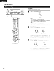
...unit. • £ OFF The power turns off from the remote control unit. 2 Turn on and off and indicator is light. Press the Power ON/STANDBY switch (button). (Main unit) (Remote control unit) When pressed, the power turns on the remote control unit. 34 ENGLISH 12 OPERATION Before operating 21 3 2... power cannot be changed with the SPEAKER button on and the display lights. The sound is set and the display turns off , the standby mode is muted for several seconds, after which the unit operates normally. When pressed again, the power turns off . 3 Select the front speakers....
...unit. • £ OFF The power turns off from the remote control unit. 2 Turn on and off and indicator is light. Press the Power ON/STANDBY switch (button). (Main unit) (Remote control unit) When pressed, the power turns on the remote control unit. 34 ENGLISH 12 OPERATION Before operating 21 3 2... power cannot be changed with the SPEAKER button on and the display lights. The sound is set and the display turns off , the standby mode is muted for several seconds, after which the unit operates normally. When pressed again, the power turns off . 3 Select the front speakers....

Owners Manual
Page 64
... set 's power, then ventilate it well to minimum. • MUTING is being input. 15, 16 35 36 37 36 DISPLAY not displayed and the "ON/STANDBY" LED flashes at continuous high power conditions and/or inadequate ventilation. • Switch power off, connect speakers properly, then switch power back on . • Turn...
... set 's power, then ventilate it well to minimum. • MUTING is being input. 15, 16 35 36 37 36 DISPLAY not displayed and the "ON/STANDBY" LED flashes at continuous high power conditions and/or inadequate ventilation. • Switch power off, connect speakers properly, then switch power back on . • Turn...


