
Literature/Product Sheet
Page 2
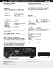
... CANADA L3R 1B5 TEL: 905-475-4085 www.denon.ca NIPPON COLUMBIA CO., LTD. 14-14, AKASAKA 4-CHOME, MINATO-KU, TOKYO 107-8011, JAPAN Front panel with remote control codes from digital sources such as CD. • Front Panel Inputs The AVR-1602's front panel includes 1 set of video and... audio input terminals where you can customize the performance of -use of a second pair of DENON's high-grade A/V amplifiers, the AVR-1602 lets you adjust ...
... CANADA L3R 1B5 TEL: 905-475-4085 www.denon.ca NIPPON COLUMBIA CO., LTD. 14-14, AKASAKA 4-CHOME, MINATO-KU, TOKYO 107-8011, JAPAN Front panel with remote control codes from digital sources such as CD. • Front Panel Inputs The AVR-1602's front panel includes 1 set of video and... audio input terminals where you can customize the performance of -use of a second pair of DENON's high-grade A/V amplifiers, the AVR-1602 lets you adjust ...
Owners Manual
Page 4
... instructions along with the warranty in a safe place. • Note that the illustrations in a safe place. Using the Remote Control Unit 15 ⁄0 Setting up the Speaker Systems 8 , Connections 9~14 . AUX terminal The AVR-1602's front panel is provided with a V. TABLE OF CONTENTS z Before Using 4 x Cautions on Installation 5 c Cautions on Check once again... terminal when you want to the standby position before proceeding. AUX terminal. ENGLISH 2 INTRODUCTION Thank you for explanation purposes. • V. Always set for choosing the DENON A/V Surround receiver.
... instructions along with the warranty in a safe place. • Note that the illustrations in a safe place. Using the Remote Control Unit 15 ⁄0 Setting up the Speaker Systems 8 , Connections 9~14 . AUX terminal The AVR-1602's front panel is provided with a V. TABLE OF CONTENTS z Before Using 4 x Cautions on Installation 5 c Cautions on Check once again... terminal when you want to the standby position before proceeding. AUX terminal. ENGLISH 2 INTRODUCTION Thank you for explanation purposes. • V. Always set for choosing the DENON A/V Surround receiver.

Owners Manual
Page 5
... the tuner or TV away from sources such as laser disc, DVD and specially-encoded music discs. 4. Remote control unit with pre-memory function This unit comes with a remote control unit equipped with no crosstalk between the top, back and sides of this time, the output will ...of PRE OUT jack, HEADPHONE jack and SPEAKER terminals The PRE OUT jack, HEADPHONE jack and SPEAKER terminals include a muting circuit. The remote control command codes for DENON remote controllable AV components as well as the range of CDs, thus resulting in clearer, more wall 3 CAUTIONS ON HANDLING • Switching...
... the tuner or TV away from sources such as laser disc, DVD and specially-encoded music discs. 4. Remote control unit with pre-memory function This unit comes with a remote control unit equipped with no crosstalk between the top, back and sides of this time, the output will ...of PRE OUT jack, HEADPHONE jack and SPEAKER terminals The PRE OUT jack, HEADPHONE jack and SPEAKER terminals include a muting circuit. The remote control command codes for DENON remote controllable AV components as well as the range of CDs, thus resulting in clearer, more wall 3 CAUTIONS ON HANDLING • Switching...

Owners Manual
Page 6
... 26) @1 Display @2 TUNING UP/DOWN button 40) @3 MEMORY button 39, 41) @4 MODE button 40) @5 BAND button 40) @6 SIGNAL indicators 26) @7 INPUT mode indicators 26) @8 Remote control sensor (REMOTE SENSOR 15) @9 Power operation indicator #0 Input source selector buttons 25, 32) 6 IN button 25, 28) i TONE DEFEAT button 26) o VIRTUAL SURROUND button 34, 35...
... 26) @1 Display @2 TUNING UP/DOWN button 40) @3 MEMORY button 39, 41) @4 MODE button 40) @5 BAND button 40) @6 SIGNAL indicators 26) @7 INPUT mode indicators 26) @8 Remote control sensor (REMOTE SENSOR 15) @9 Power operation indicator #0 Input source selector buttons 25, 32) 6 IN button 25, 28) i TONE DEFEAT button 26) o VIRTUAL SURROUND button 34, 35...
Owners Manual
Page 7
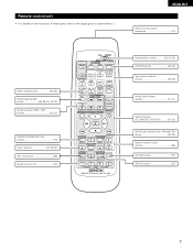
ENGLISH Remote control signal transmitter 15) INPUT MODE button 25, 28) SURROUND MODE button 26, 29, 30, 32, 35) System buttons (TAPE, VCR) buttons 21, 23) SYSTEM (SYSTEM SET UP) buttons 16) Cursor buttons 16, 32, 35) Test tone button 29) System buttons (TV 23) CD MD/CDR AVR/AVC ON ...AUDIO POWER TV VCR VIDEO DVD/VDP OFF 1 CD DVD/VDP 2 3 V. Remote control unit • For details on the functions of these parts, refer to the pages given in parentheses ( ). ...
ENGLISH Remote control signal transmitter 15) INPUT MODE button 25, 28) SURROUND MODE button 26, 29, 30, 32, 35) System buttons (TAPE, VCR) buttons 21, 23) SYSTEM (SYSTEM SET UP) buttons 16) Cursor buttons 16, 32, 35) Test tone button 29) System buttons (TV 23) CD MD/CDR AVR/AVC ON ...AUDIO POWER TV VCR VIDEO DVD/VDP OFF 1 CD DVD/VDP 2 3 V. Remote control unit • For details on the functions of these parts, refer to the pages given in parentheses ( ). ...
Owners Manual
Page 8
Step 2 (page 15) Next, insert the batteries into the remote control unit. Following these at the sides of the TV or screen with their front surfaces as flush with the front of the screen as ...
Step 2 (page 15) Next, insert the batteries into the remote control unit. Following these at the sides of the TV or screen with their front surfaces as flush with the front of the screen as ...

Owners Manual
Page 9
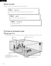
... MONITOR VCR S-VIDEO SPEAKER SYSTEMS B FRONT A CENTER R L RL SURROUND R L AC OUTLETS AC 120V 60Hz SWITCHED TOTAL 120W(1A.) MAX. No power is supplied from the remote control unit. OPTICAL B OUTPUT INPUT OUTPUT RL CD player RL DIGITAL AUDIO DIGITAL jacks Use these for hair driers, etc. Incomplete connections will result in...
... MONITOR VCR S-VIDEO SPEAKER SYSTEMS B FRONT A CENTER R L RL SURROUND R L AC OUTLETS AC 120V 60Hz SWITCHED TOTAL 120W(1A.) MAX. No power is supplied from the remote control unit. OPTICAL B OUTPUT INPUT OUTPUT RL CD player RL DIGITAL AUDIO DIGITAL jacks Use these for hair driers, etc. Incomplete connections will result in...
Owners Manual
Page 15
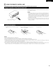
... shorten or operation will become difficult if there are correct. (See the illustration inside the battery compartment.) • Remove the batteries if the remote control transmitter will not be replaced as quickly as possible. e Close the lid. Replace it come in malfunction, so keep the set as ...nearby the set. (The included battery is only for replacement. • Be sure the polarities are obstacles between the remote control unit and the remote control sensor, if the remote control sensor is exposed to direct sunlight or other strong light, or if operated from an angle. • Neon ...
... shorten or operation will become difficult if there are correct. (See the illustration inside the battery compartment.) • Remove the batteries if the remote control transmitter will not be replaced as quickly as possible. e Close the lid. Replace it come in malfunction, so keep the set as ...nearby the set. (The included battery is only for replacement. • Be sure the polarities are obstacles between the remote control unit and the remote control sensor, if the remote control sensor is exposed to direct sunlight or other strong light, or if operated from an angle. • Neon ...

Owners Manual
Page 17
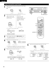
...1 Check that point are correct, then press the POWER operation switch on the main unit or the POWER button on the remote control unit to turn on the power. (Main unit) (Remote control unit) 2 Press the SYSTEM button to enter the setting. *SYSTEM SET UP NOTE: Please make sure the "AUDIO"... position of the slide switch on the remote control unit. 3 Press the SELECT or (down) button to switch to the surround speaker setting. System set up can be selected for the front speakers...
...1 Check that point are correct, then press the POWER operation switch on the main unit or the POWER button on the remote control unit to turn on the power. (Main unit) (Remote control unit) 2 Press the SYSTEM button to enter the setting. *SYSTEM SET UP NOTE: Please make sure the "AUDIO"... position of the slide switch on the remote control unit. 3 Press the SELECT or (down) button to switch to the surround speaker setting. System set up can be selected for the front speakers...
Owners Manual
Page 21
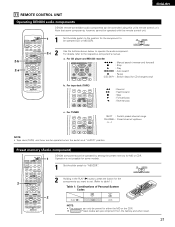
...) and tuner can be controlled using this remote control unit. 2-b 2-a CD MD/CDR AVR/AVC ON AUDIO POWER TV VCR VIDEO DVD/VDP OFF 1 CD DVD/VDP 2 3 V. ENGLISH 0 0 0 0 11 REMOTE CONTROL UNIT Operating DENON audio components DENON remote-controllable audio components can be operated when the...SET UP MENU MASTER CH SELECT VOL SELECT T.TONE STATUS MUTING RETURN DISPLAY CHANNEL TV VOLUME B REMOTE CONTROL UNIT RC-896 1 2 DENON components can only be operated with this unit's remote control unit. CD AUDIO MD/CDR VIDEO 2 Holding in the PLAY (1) button, press the button...
...) and tuner can be controlled using this remote control unit. 2-b 2-a CD MD/CDR AVR/AVC ON AUDIO POWER TV VCR VIDEO DVD/VDP OFF 1 CD DVD/VDP 2 3 V. ENGLISH 0 0 0 0 11 REMOTE CONTROL UNIT Operating DENON audio components DENON remote-controllable audio components can be operated when the...SET UP MENU MASTER CH SELECT VOL SELECT T.TONE STATUS MUTING RETURN DISPLAY CHANNEL TV VOLUME B REMOTE CONTROL UNIT RC-896 1 2 DENON components can only be operated with this unit's remote control unit. CD AUDIO MD/CDR VIDEO 2 Holding in the PLAY (1) button, press the button...

Owners Manual
Page 22
ENGLISH Preset memory (Video component) DENON and other makes of components can be used . • The ... for the pressed buttons are emitted while setting the preset memory. To avoid accidental operation, cover the remote control unit's transmitting window while setting the preset memory. • Some models and years of manufacture ...1 2 3 2, 3 1 Set the slide switch to set. This remote control unit can be used to operate components of other components, repeat steps 2 to store in the memory. CD MD/CDR AVR/AVC ON AUDIO POWER TV VCR VIDEO DVD/VDP OFF 1 CD DVD/VDP...
ENGLISH Preset memory (Video component) DENON and other makes of components can be used . • The ... for the pressed buttons are emitted while setting the preset memory. To avoid accidental operation, cover the remote control unit's transmitting window while setting the preset memory. • Some models and years of manufacture ...1 2 3 2, 3 1 Set the slide switch to set. This remote control unit can be used to operate components of other components, repeat steps 2 to store in the memory. CD MD/CDR AVR/AVC ON AUDIO POWER TV VCR VIDEO DVD/VDP OFF 1 CD DVD/VDP...
Owners Manual
Page 23
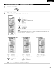
... 7 SURROUND SET UP MENU MASTER CH SELECT VOL SELECT T.TONE STATUS MUTING RETURN DISPLAY CHANNEL TV VOLUME POWER : Power on remote control for that component. a. For monitor TV AVR/AVC ON POWER TV VCR DVD/VDP OFF 1 CD DVD/VDP 2 3 V. For DVD player CD MD/CDR... (forward and reverse) 2 : Stop 1 : Play 3 : Pause CHANNEL : Switch channel (+, -) NOTE: • The TV can be operated with this remote control unit. For video deck (VCR) AVR/AVC ON POWER TV VCR DVD/VDP OFF 1 CD DVD/VDP 2 3 V. AUX 4 VCR 5 TV/DBS 6 7 INPUT MODE CDR / TAPE TUNER 8...
... 7 SURROUND SET UP MENU MASTER CH SELECT VOL SELECT T.TONE STATUS MUTING RETURN DISPLAY CHANNEL TV VOLUME POWER : Power on remote control for that component. a. For monitor TV AVR/AVC ON POWER TV VCR DVD/VDP OFF 1 CD DVD/VDP 2 3 V. For DVD player CD MD/CDR... (forward and reverse) 2 : Stop 1 : Play 3 : Pause CHANNEL : Switch channel (+, -) NOTE: • The TV can be operated with this remote control unit. For video deck (VCR) AVR/AVC ON POWER TV VCR DVD/VDP OFF 1 CD DVD/VDP 2 3 V. AUX 4 VCR 5 TV/DBS 6 7 INPUT MODE CDR / TAPE TUNER 8...

Owners Manual
Page 24
Press the ON/STANDBY button on the main unit or AVR/AVC button on the remote control unit to the "ON" position until sound is pressed, the power turns on the power. When pressed again, the power turns off . AUX 4 VCR 5 ... are required from the time the power operation switch is turned on . (Main unit) 24 This is due to turn on the power. (Main unit) (Remote control unit) • ON/STANDBY When the button is output. ENGLISH 12 OPERATION Before operating B 1 2 CD MD/CDR AUDIO VIDEO POWER...
Press the ON/STANDBY button on the main unit or AVR/AVC button on the remote control unit to the "ON" position until sound is pressed, the power turns on the power. When pressed again, the power turns off . AUX 4 VCR 5 ... are required from the time the power operation switch is turned on . (Main unit) 24 This is due to turn on the power. (Main unit) (Remote control unit) • ON/STANDBY When the button is output. ENGLISH 12 OPERATION Before operating B 1 2 CD MD/CDR AUDIO VIDEO POWER...

Owners Manual
Page 25
... through the surround circuitry. EX 1: CD CD 1 (Main unit) EX 2: CDR/TAPE (Remote control unit) CDR / TAPE 8 (Main unit) (Remote control unit) 2 Select the input mode. IN 8 (Remote control unit) 2 3 CD MD/CDR AVR/AVC ON AUDIO POWER TV VCR VIDEO DVD/VDP OFF 1 CD DVD/VDP 2 3 V....8 3 9 6 SYSTEM 2 7 SURROUND SET UP MENU MASTER CH SELECT VOL SELECT T.TONE STATUS MUTING RETURN DISPLAY CHANNEL TV VOLUME B REMOTE CONTROL UNIT RC-896 1 5 Input mode selection function Different input modes can be selected for the program source to be generated at the beginning...
... through the surround circuitry. EX 1: CD CD 1 (Main unit) EX 2: CDR/TAPE (Remote control unit) CDR / TAPE 8 (Main unit) (Remote control unit) 2 Select the input mode. IN 8 (Remote control unit) 2 3 CD MD/CDR AVR/AVC ON AUDIO POWER TV VCR VIDEO DVD/VDP OFF 1 CD DVD/VDP 2 3 V....8 3 9 6 SYSTEM 2 7 SURROUND SET UP MENU MASTER CH SELECT VOL SELECT T.TONE STATUS MUTING RETURN DISPLAY CHANNEL TV VOLUME B REMOTE CONTROL UNIT RC-896 1 5 Input mode selection function Different input modes can be selected for the program source to be generated at the beginning...

Owners Manual
Page 26
...the surround mode while adjusting the surround parameters, channel volume or tone control, press the surround mode button then operate the selector. (See page 29.) (Remote control unit) (Main unit) 4 Start playback on the selected component. • For operating instructions, refer to 18 dB. (In this case the ...maximum volume adjustment range is displayed on the master volume level display. (Main unit) (Remote control unit) The volume can be decreased to up to the component's manual. 5 Adjust the volume. ENGLISH 3 Select the play mode.
...the surround mode while adjusting the surround parameters, channel volume or tone control, press the surround mode button then operate the selector. (See page 29.) (Remote control unit) (Main unit) 4 Start playback on the selected component. • For operating instructions, refer to 18 dB. (In this case the ...maximum volume adjustment range is displayed on the master volume level display. (Main unit) (Remote control unit) The volume can be decreased to up to the component's manual. 5 Adjust the volume. ENGLISH 3 Select the play mode.

Owners Manual
Page 27
Muting will also be DISPLAY switched to check the unit's operating status (Main unit) (Remote control unit) while playing a source by pressing the main unit's DIMMER button repeatedly. (Main unit) The brightness changes in four steps (...to 1 the video input. [5] Checking the currently playing program source, etc. 1 Front panel display • Descriptions of the unit's operations are turned on (Main unit) (Remote control unit) 1 VIDEO SELECT CD·MD/CDR·DVD/VDP DISC SKIP+ TITLE 8 3 9 the display. 2 6 7 Cancelling simulcast playback. • Select "...
Muting will also be DISPLAY switched to check the unit's operating status (Main unit) (Remote control unit) while playing a source by pressing the main unit's DIMMER button repeatedly. (Main unit) The brightness changes in four steps (...to 1 the video input. [5] Checking the currently playing program source, etc. 1 Front panel display • Descriptions of the unit's operations are turned on (Main unit) (Remote control unit) 1 VIDEO SELECT CD·MD/CDR·DVD/VDP DISC SKIP+ TITLE 8 3 9 the display. 2 6 7 Cancelling simulcast playback. • Select "...

Owners Manual
Page 28
...the INPUT MODE (AUTO, PCM, DTS) or ANALOG button to switch to the desired input mode. (See page 25.) 8 (Main unit) (Remote control unit) • When the input mode is selected, the input signals connected to the DIGITAL OUT (OPTICAL) jack. 28 Simultaneous recording The ...signals of the source selected with the function selector button are output simultaneously to switch the external input. (Main unit) (Remote control unit) Once this mode. For instructions, refer to the input jacks. • The external input mode can be set to 3 ...
...the INPUT MODE (AUTO, PCM, DTS) or ANALOG button to switch to the desired input mode. (See page 25.) 8 (Main unit) (Remote control unit) • When the input mode is selected, the input signals connected to the DIGITAL OUT (OPTICAL) jack. 28 Simultaneous recording The ...signals of the source selected with the function selector button are output simultaneously to switch the external input. (Main unit) (Remote control unit) Once this mode. For instructions, refer to the input jacks. • The external input mode can be set to 3 ...

Owners Manual
Page 29
...FL CNTR FR SR SL SW NOTE: Please make sure the "AUDIO" position of the slide switch on the remote control unit. 2 Adjust the level of the selected speaker. (Main unit) (Remote control unit) The level of the selected speaker can be performed from the different speakers. The adjusted playback levels ... test tones is only effective in the memory of each time the button is the same for the different surround modes are output from the remote control unit, as shown below each surround modes. 1 Set the DOLBY/DTS SURROUND (Dolby Pro Logic II or Dolby Digital or DTS) modes. ...
...FL CNTR FR SR SL SW NOTE: Please make sure the "AUDIO" position of the slide switch on the remote control unit. 2 Adjust the level of the selected speaker. (Main unit) (Remote control unit) The level of the selected speaker can be performed from the different speakers. The adjusted playback levels ... test tones is only effective in the memory of each time the button is the same for the different surround modes are output from the remote control unit, as shown below each surround modes. 1 Set the DOLBY/DTS SURROUND (Dolby Pro Logic II or Dolby Digital or DTS) modes. ...
Owners Manual
Page 30
...button is set to "AUDIO". 5 Select the optimum mode for the source. (Main unit) (Remote control unit) MODE PRO LOGIC MODE CINEMA MODE MUSIC or or 1 2 4, 6 2, 5, 7 1 2 4, 5, 6, 7 CD MD/CDR AVR/AVC ON AUDIO POWER TV VCR VIDEO DVD/VDP OFF 1 CD DVD/VDP 2 3 V. ...Select the DOLBY PRO LOGIC II mode. Display SURROUND MODE CINEMA MENU (Main unit) (Remote control unit) To perform this operation from the remote control unit, check that the mode selector switch...
...button is set to "AUDIO". 5 Select the optimum mode for the source. (Main unit) (Remote control unit) MODE PRO LOGIC MODE CINEMA MODE MUSIC or or 1 2 4, 6 2, 5, 7 1 2 4, 5, 6, 7 CD MD/CDR AVR/AVC ON AUDIO POWER TV VCR VIDEO DVD/VDP OFF 1 CD DVD/VDP 2 3 V. ...Select the DOLBY PRO LOGIC II mode. Display SURROUND MODE CINEMA MENU (Main unit) (Remote control unit) To perform this operation from the remote control unit, check that the mode selector switch...

Owners Manual
Page 32
DIGITAL • The Dolby Digital indicator lights when Light playing Dolby Digital sources. 1 22 1 2 5, 6, 7, 8 CD MD/CDR AVR/AVC ON AUDIO POWER TV VCR VIDEO DVD/VDP OFF 1 CD DVD/VDP 2 3 V. MENU NOTE: Please make sure the "AUDIO" position of the ... the main unit's panel, press the SURROUND MODE button, then press the SELECT buttons and select "DOLBY/DTS". • The following appears on the remote control unit. (Remote control unit) 5 Use the (left ) button (right) button (down) button to switch to the D. COMP. First, press the SURROUND button. Playback with ...
DIGITAL • The Dolby Digital indicator lights when Light playing Dolby Digital sources. 1 22 1 2 5, 6, 7, 8 CD MD/CDR AVR/AVC ON AUDIO POWER TV VCR VIDEO DVD/VDP OFF 1 CD DVD/VDP 2 3 V. MENU NOTE: Please make sure the "AUDIO" position of the ... the main unit's panel, press the SURROUND MODE button, then press the SELECT buttons and select "DOLBY/DTS". • The following appears on the remote control unit. (Remote control unit) 5 Use the (left ) button (right) button (down) button to switch to the D. COMP. First, press the SURROUND button. Playback with ...


