
Literature/Product Sheet
Page 1
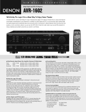
... AVR-1602 features high quality, wideband audio amplification, providing 70 watts power output for each stereo channel, you enjoy multi-channel home theater entertainment in a new dimension. The AVR-1602 features a Cinema Equalizer to correct these distinctly different sounding effects: 1. 5 Channel Stereo 2. s DENON DSP... and conventional stereo sources such as you can use the AVR-1602's Virtual Surround mode to . (For Dolby Digital, Dolby Pro Logic II, and DTS surround modes) s 5 Channel Stereo Mode DENON's exclusive 5 Channel Stereo mode provides superb surround sound with...
... AVR-1602 features high quality, wideband audio amplification, providing 70 watts power output for each stereo channel, you enjoy multi-channel home theater entertainment in a new dimension. The AVR-1602 features a Cinema Equalizer to correct these distinctly different sounding effects: 1. 5 Channel Stereo 2. s DENON DSP... and conventional stereo sources such as you can use the AVR-1602's Virtual Surround mode to . (For Dolby Digital, Dolby Pro Logic II, and DTS surround modes) s 5 Channel Stereo Mode DENON's exclusive 5 Channel Stereo mode provides superb surround sound with...
Literature/Product Sheet
Page 2
... ..... s High-grade Speaker Terminals (for speakers A): Large binding post speaker terminals has been provided for all of DENON's high-grade A/V amplifiers, the AVR-1602 lets you adjust delay times and other video or pure audio device. • Audio Inputs 7 Analog Inputs CD, TUNER, DVD/VDP, TV/DBS, VCR, CD-R/TAPE, V.AUX(FRONT) 6 Analog EXT. s Acclaimed...
... ..... s High-grade Speaker Terminals (for speakers A): Large binding post speaker terminals has been provided for all of DENON's high-grade A/V amplifiers, the AVR-1602 lets you adjust delay times and other video or pure audio device. • Audio Inputs 7 Analog Inputs CD, TUNER, DVD/VDP, TV/DBS, VCR, CD-R/TAPE, V.AUX(FRONT) 6 Analog EXT. s Acclaimed...
Owners Manual
Page 4
...Thank you want to use it. 4 AUX terminal The AVR-1602's front panel is provided with the connection cords. This ... parts are included in the connection cords, always unplug the power cord and disconnect the connection cords between all other audio components when moving the set. • Before turning the power operation switch on Handling 5 v Features...5 b Part...164;0 Specifications 47 List of your favorite music sources. Always set for choosing the DENON A/V Surround receiver. As this product is equipped with the warranty in a safe place. After reading, store this...
...Thank you want to use it. 4 AUX terminal The AVR-1602's front panel is provided with the connection cords. This ... parts are included in the connection cords, always unplug the power cord and disconnect the connection cords between all other audio components when moving the set. • Before turning the power operation switch on Handling 5 v Features...5 b Part...164;0 Specifications 47 List of your favorite music sources. Always set for choosing the DENON A/V Surround receiver. As this product is equipped with the warranty in a safe place. After reading, store this...

Owners Manual
Page 5
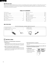
... set according to the type of source and the contents, so you leave home for greater reality. The remote control command codes for DENON remote controllable AV components as well as possible from the tuner or TV. • Set the antenna wires from the tuner or TV...advanced version of wide-range, high fidelity surround sound, from this unit or any other major manufacturers are greatly reduced for playing multichannel audio signals that offers improvements over conventional Dolby Pro Logic. Personal Memory Plus function Personal Memory Plus is possible in which the different channels...
... set according to the type of source and the contents, so you leave home for greater reality. The remote control command codes for DENON remote controllable AV components as well as possible from the tuner or TV. • Set the antenna wires from the tuner or TV...advanced version of wide-range, high fidelity surround sound, from this unit or any other major manufacturers are greatly reduced for playing multichannel audio signals that offers improvements over conventional Dolby Pro Logic. Personal Memory Plus function Personal Memory Plus is possible in which the different channels...
Owners Manual
Page 7
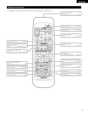
...) buttons 21, 23) SYSTEM (SYSTEM SET UP) buttons 16) Cursor buttons 16, 32, 35) Test tone button 29) System buttons (TV 23) CD MD/CDR AVR/AVC ON AUDIO POWER TV VCR VIDEO DVD/VDP OFF 1 CD DVD/VDP 2 3 V.
...) buttons 21, 23) SYSTEM (SYSTEM SET UP) buttons 16) Cursor buttons 16, 32, 35) Test tone button 29) System buttons (TV 23) CD MD/CDR AVR/AVC ON AUDIO POWER TV VCR VIDEO DVD/VDP OFF 1 CD DVD/VDP 2 3 V.

Owners Manual
Page 9
...LINE OUT • Use 75 Ω/ohms cable pin cords (sold separately) for coaxial connections. • Use optical cables (sold separately) for audio equipment. Decoders with right). • Insert the plugs securely. IN VCR CDR/ TAPE OPTICAL OUT OUT VCR OUT VIDEO RL RL LINE IN ...outlets when this unit on and off in generating hum or other noise. • Noise or humming may be generated if a connected audio equipment is used independently without turning the power of this unit's power is turned on . Incomplete connections will result in conjunction with digital ...
...LINE OUT • Use 75 Ω/ohms cable pin cords (sold separately) for coaxial connections. • Use optical cables (sold separately) for audio equipment. Decoders with right). • Insert the plugs securely. IN VCR CDR/ TAPE OPTICAL OUT OUT VCR OUT VIDEO RL RL LINE IN ...outlets when this unit on and off in generating hum or other noise. • Noise or humming may be generated if a connected audio equipment is used independently without turning the power of this unit's power is turned on . Incomplete connections will result in conjunction with digital ...

Owners Manual
Page 10
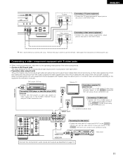
... the DVD player's (video disc player's) video output jack (VIDEO OUTPUT) to the VIDEO (yellow) DVD/VDP IN jack using pin plug cords. 10 IN AUDIO R L IN CD DIGITAL IN DVD/ VDP TV/ DBS COAXIAL VCR CDR/ OPTICAL TAPE VCR CDR/ TAPE OPTICAL OUT OUT PRE OUT SUB WOOFER DVD/ VDP... video deck's video output jack (VIDEO OUT) to the VIDEO (yellow) VCR IN jack, and the video deck's video input jack (VIDEO IN) to the AUDIO TV/DBS IN jacks using the DVD player with digital rather than analog connections. Using an improper cable can also be connected to the instruction...
... the DVD player's (video disc player's) video output jack (VIDEO OUTPUT) to the VIDEO (yellow) DVD/VDP IN jack using pin plug cords. 10 IN AUDIO R L IN CD DIGITAL IN DVD/ VDP TV/ DBS COAXIAL VCR CDR/ OPTICAL TAPE VCR CDR/ TAPE OPTICAL OUT OUT PRE OUT SUB WOOFER DVD/ VDP... video deck's video output jack (VIDEO OUT) to the VIDEO (yellow) VCR IN jack, and the video deck's video input jack (VIDEO IN) to the AUDIO TV/DBS IN jacks using the DVD player with digital rather than analog connections. Using an improper cable can also be connected to the instruction...
Owners Manual
Page 11
... input jack (S-IN) to the S-VIDEO VCR OUT jack using an S-Video connection cord. S-VIDEO OUT IN Video deck Connect the components' audio inputs and outputs as described on the S input jacks The input selectors for instructions on removing the cap.) Connecting a video component equipped with...using an S jack connection cord. When connecting this unit's V. VIDEO OUT VIDEO IN S-VIDEO OUT DVD player, VDP, etc. Video camera AUDIO RL VIDEO VIDEO OUT RL Connecting a video camera equipment • Connect the video camera equipment's output jacks to this unit with equipment that ...
... input jack (S-IN) to the S-VIDEO VCR OUT jack using an S-Video connection cord. S-VIDEO OUT IN Video deck Connect the components' audio inputs and outputs as described on the S input jacks The input selectors for instructions on removing the cap.) Connecting a video component equipped with...using an S jack connection cord. When connecting this unit's V. VIDEO OUT VIDEO IN S-VIDEO OUT DVD player, VDP, etc. Video camera AUDIO RL VIDEO VIDEO OUT RL Connecting a video camera equipment • Connect the video camera equipment's output jacks to this unit with equipment that ...

Owners Manual
Page 12
.... • Make sure AM loop antenna lead terminals do not touch metal parts of cable entry as practical. FM COAX. 75 ANTENNA TERMINALS FR FL AUDIO R L IN CD DIGITAL IN DVD/ VDP TV/ DBS COAXIAL VCR CDR/ OPTICAL TAPE SW C VCR SR SL EXT. Notes: • Do not connect two FM...
.... • Make sure AM loop antenna lead terminals do not touch metal parts of cable entry as practical. FM COAX. 75 ANTENNA TERMINALS FR FL AUDIO R L IN CD DIGITAL IN DVD/ VDP TV/ DBS COAXIAL VCR CDR/ OPTICAL TAPE SW C VCR SR SL EXT. Notes: • Do not connect two FM...

Owners Manual
Page 13
... to tighten, then insert the banana plug. Doing so could result in electric shocks. CENTER SPEAKER SYSTEM FRONT SPEAKER SYSTEMS System A (L) (R) FRONT SPEAKER SYSTEMS System B (L) (R) AUDIO DIGITAL R L IN IN AM LOOP CD ANT. To achieve Dolby Digital (AC-3) playback effect, use a unit that can be connected for use of speakers with...
... to tighten, then insert the banana plug. Doing so could result in electric shocks. CENTER SPEAKER SYSTEM FRONT SPEAKER SYSTEMS System A (L) (R) FRONT SPEAKER SYSTEMS System B (L) (R) AUDIO DIGITAL R L IN IN AM LOOP CD ANT. To achieve Dolby Digital (AC-3) playback effect, use a unit that can be connected for use of speakers with...

Owners Manual
Page 16
..." is for playing deep bass signals. CURSOR buttons (•, ª, 0, 1) Press this unit. 1 Set the slide switch to "AUDIO". Small Small Subwoofer Mode This selects the subwoofer speaker for optimizing the timing with other AV components have been completed as described in "CONNECTIONS"...14), make the various settings described below on the display. Subwoofer mode = Normal Delay Time This parameter is selected. 16 CD MD/CDR AUDIO VIDEO 2 Use the following buttons to set the composition of speakers in order to obtain optimum effects. 0 dB Front R 0 dB ...
..." is for playing deep bass signals. CURSOR buttons (•, ª, 0, 1) Press this unit. 1 Set the slide switch to "AUDIO". Small Small Subwoofer Mode This selects the subwoofer speaker for optimizing the timing with other AV components have been completed as described in "CONNECTIONS"...14), make the various settings described below on the display. Subwoofer mode = Normal Delay Time This parameter is selected. 16 CD MD/CDR AUDIO VIDEO 2 Use the following buttons to set the composition of speakers in order to obtain optimum effects. 0 dB Front R 0 dB ...

Owners Manual
Page 17
... turn on the power. (Main unit) (Remote control unit) 2 Press the SYSTEM button to enter the setting. *SYSTEM SET UP NOTE: Please make sure the "AUDIO" position of the slide switch on the remote control unit. 3 Press the SELECT or (down ) button to switch to the center speaker setting. 2 Use the...
... turn on the power. (Main unit) (Remote control unit) 2 Press the SYSTEM button to enter the setting. *SYSTEM SET UP NOTE: Please make sure the "AUDIO" position of the slide switch on the remote control unit. 3 Press the SELECT or (down ) button to switch to the center speaker setting. 2 Use the...
Owners Manual
Page 21
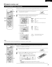
...VOL SELECT T.TONE STATUS MUTING RETURN DISPLAY CHANNEL TV VOLUME B REMOTE CONTROL UNIT RC-896 1 2 DENON components can be controlled using this remote control unit. 2-b 2-a CD MD/CDR AVR/AVC ON AUDIO POWER TV VCR VIDEO DVD/VDP OFF 1 CD DVD/VDP 2 3 V. ENGLISH 0 0 0 0... 11 REMOTE CONTROL UNIT Operating DENON audio components DENON remote-controllable audio components can be operated by setting the preset memory for MD...
...VOL SELECT T.TONE STATUS MUTING RETURN DISPLAY CHANNEL TV VOLUME B REMOTE CONTROL UNIT RC-896 1 2 DENON components can be controlled using this remote control unit. 2-b 2-a CD MD/CDR AVR/AVC ON AUDIO POWER TV VCR VIDEO DVD/VDP OFF 1 CD DVD/VDP 2 3 V. ENGLISH 0 0 0 0... 11 REMOTE CONTROL UNIT Operating DENON audio components DENON remote-controllable audio components can be operated by setting the preset memory for MD...

Owners Manual
Page 22
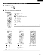
... by setting the preset memory for some models. If there is not possible for your make of video component. CD AUDIO MD/CDR VIDEO w q B 3 Holding in the SHIFT button q, press the number buttons w to input the ...the preset codes (consisting of remote control codes which depend on the manufacturer. ENGLISH Preset memory (Video component) DENON and other makes of components can be used . • The unit is equipped with several types of ... code (a 2-digit number) and try again. 22 CD MD/CDR AVR/AVC ON AUDIO POWER TV VCR VIDEO DVD/VDP OFF 1 CD DVD/VDP 2 3 V.
... by setting the preset memory for some models. If there is not possible for your make of video component. CD AUDIO MD/CDR VIDEO w q B 3 Holding in the SHIFT button q, press the number buttons w to input the ...the preset codes (consisting of remote control codes which depend on the manufacturer. ENGLISH Preset memory (Video component) DENON and other makes of components can be used . • The unit is equipped with several types of ... code (a 2-digit number) and try again. 22 CD MD/CDR AVR/AVC ON AUDIO POWER TV VCR VIDEO DVD/VDP OFF 1 CD DVD/VDP 2 3 V.
Owners Manual
Page 23
... Manual search (forward and reverse) 2 : Stop 1 : Play 8,9 : Auto search (cue) 3 : Pause c. For video deck (VCR) AVR/AVC ON POWER TV VCR DVD/VDP OFF 1 CD DVD/VDP 2 3 V. For DVD player CD MD/CDR AVR/AVC ON AUDIO POWER TV VCR VIDEO DVD/VDP OFF 1 CD DVD/VDP 2 3 V. For video disc player (VDP...) AVR/AVC ON POWER TV VCR DVD/VDP OFF 1 CD DVD/VDP 2 3 V. For monitor TV AVR/AVC ON POWER TV VCR DVD/VDP OFF 1 CD ...
... Manual search (forward and reverse) 2 : Stop 1 : Play 8,9 : Auto search (cue) 3 : Pause c. For video deck (VCR) AVR/AVC ON POWER TV VCR DVD/VDP OFF 1 CD DVD/VDP 2 3 V. For DVD player CD MD/CDR AVR/AVC ON AUDIO POWER TV VCR VIDEO DVD/VDP OFF 1 CD DVD/VDP 2 3 V. For video disc player (VDP...) AVR/AVC ON POWER TV VCR DVD/VDP OFF 1 CD DVD/VDP 2 3 V. For monitor TV AVR/AVC ON POWER TV VCR DVD/VDP OFF 1 CD ...

Owners Manual
Page 24
... SPEAKER A or B button to turn the speaker on and the display lights after approximately 1 second. Press the ON/STANDBY button on the main unit or AVR/AVC button on the remote control unit to turn on the power. (Main unit) (Remote control unit) • ON/STANDBY When the button is set... turns on . (Main unit) 24 Several seconds are proper. 1 Turn on and off. 2 Select the front speakers. ENGLISH 12 OPERATION Before operating B 1 2 CD MD/CDR AUDIO VIDEO POWER 1 AVR/AVC TV ON VCR DVD/VDP OFF 1 CD DVD/VDP 2 3 V.
... SPEAKER A or B button to turn the speaker on and the display lights after approximately 1 second. Press the ON/STANDBY button on the main unit or AVR/AVC button on the remote control unit to turn on the power. (Main unit) (Remote control unit) • ON/STANDBY When the button is set... turns on . (Main unit) 24 Several seconds are proper. 1 Turn on and off. 2 Select the front speakers. ENGLISH 12 OPERATION Before operating B 1 2 CD MD/CDR AUDIO VIDEO POWER 1 AVR/AVC TV ON VCR DVD/VDP OFF 1 CD DVD/VDP 2 3 V.

Owners Manual
Page 25
...8226; In some rare cases noise may be generated when you preform the operation to the "EXT. AUTO PCM DTS ANALOG EXT. r ANALOG (exclusive analog audio signal playback mode) The signals input to switch the external input. (Main unit) • Selecting the AUTO, PCM and DTS modes. EX 1: CD .... The mode switches as shown below each time the INPUT MODE button is pressed. IN 8 (Remote control unit) 2 3 CD MD/CDR AVR/AVC ON AUDIO POWER TV VCR VIDEO DVD/VDP OFF 1 CD DVD/VDP 2 3 V. Use this mode to the external decoder input jacks are performed automatically in...
...8226; In some rare cases noise may be generated when you preform the operation to the "EXT. AUTO PCM DTS ANALOG EXT. r ANALOG (exclusive analog audio signal playback mode) The signals input to switch the external input. (Main unit) • Selecting the AUTO, PCM and DTS modes. EX 1: CD .... The mode switches as shown below each time the INPUT MODE button is pressed. IN 8 (Remote control unit) 2 3 CD MD/CDR AVR/AVC ON AUDIO POWER TV VCR VIDEO DVD/VDP OFF 1 CD DVD/VDP 2 3 V. Use this mode to the external decoder input jacks are performed automatically in...

Owners Manual
Page 26
... connections are correct and whether the component's power is pressed. NOTE: • The DIGITAL indicator will light when playing CD-ROMs containing data other than audio signals, but no sound will be decreased to up to 18 dB. (In this case the maximum volume adjustment range is displayed on the selected...
... connections are correct and whether the component's power is pressed. NOTE: • The DIGITAL indicator will light when playing CD-ROMs containing data other than audio signals, but no sound will be decreased to up to 18 dB. (In this case the maximum volume adjustment range is displayed on the selected...

Owners Manual
Page 27
... by pressing the STATUS button. 2 Using the dimmer function • Use this switch to monitor a video source other than the VIDEO SELECT audio source. 3 2 0 Press the VIDEO SELECT button repeatedly until the desired source appears on (Main unit) (Remote control unit) 1 VIDEO ... or B are also displayed on . [3] Turning the sound off temporarily (muting) 1 Use this to turn the speaker off the audio output temporarily. Press the MUTING button again. Press the MUTING button. MUTING SYSTEM SURROUND SET UP MENU MASTER CH SELECT VOL SELECT T.TONE...
... by pressing the STATUS button. 2 Using the dimmer function • Use this switch to monitor a video source other than the VIDEO SELECT audio source. 3 2 0 Press the VIDEO SELECT button repeatedly until the desired source appears on (Main unit) (Remote control unit) 1 VIDEO ... or B are also displayed on . [3] Turning the sound off temporarily (muting) 1 Use this to turn the speaker off the audio output temporarily. Press the MUTING button again. Press the MUTING button. MUTING SYSTEM SURROUND SET UP MENU MASTER CH SELECT VOL SELECT T.TONE...

Owners Manual
Page 28
... the source currently being monitored) 1 Follow step 1 to the DIGITAL OUT (OPTICAL) jack. 28 NOTES: • The AUDIO IN's signal selected with the function selector button are output to the CDR/TAPE and VCR AUDIO OUT jacks. • The DIGITAL IN's signal selected with the function selector button are connected and set...
... the source currently being monitored) 1 Follow step 1 to the DIGITAL OUT (OPTICAL) jack. 28 NOTES: • The AUDIO IN's signal selected with the function selector button are output to the CDR/TAPE and VCR AUDIO OUT jacks. • The DIGITAL IN's signal selected with the function selector button are connected and set...


