User Manual
Page 1
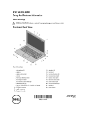
... View Figure 1. Secure Digital (SD) 8- USB 3.0 connector 11. audio connector 12. Dell Vostro 3360 Setup And Features Information About Warnings WARNING: A WARNING indicates a potential for property damage, personal injury, or death. microphone (2) 2. camera 3. Windows Mobility Center 6. fingerprint reader 13. touchpad buttons (2) 16. power status light 20. Dell Instant Launch Manager 8. touchpad 15. camera status light 4. touchpad status light 21. hard disk status light 19. wireless status light 17. Front View 1. keyboard 22. Dell Support Center 7.
... View Figure 1. Secure Digital (SD) 8- USB 3.0 connector 11. audio connector 12. Dell Vostro 3360 Setup And Features Information About Warnings WARNING: A WARNING indicates a potential for property damage, personal injury, or death. microphone (2) 2. camera 3. Windows Mobility Center 6. fingerprint reader 13. touchpad buttons (2) 16. power status light 20. Dell Instant Launch Manager 8. touchpad 15. camera status light 4. touchpad status light 21. hard disk status light 19. wireless status light 17. Front View 1. keyboard 22. Dell Support Center 7.
User Manual
Page 2
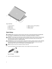
.... For additional best practices information, see www.dell.com/regulatory_compliance. WARNING: The AC adapter works with PowerShare 6. Connect the AC adapter to the AC adapter connector on the AC adapter to the electrical outlet. Connect the network cable (optional). 2 Figure 2. VGA connector 4. security cable slot 2. CAUTION: When you did not order them. 1. Figure 3. Back View 1. HDMI connector Quick Setup WARNING: Before you follow the angle of the...
.... For additional best practices information, see www.dell.com/regulatory_compliance. WARNING: The AC adapter works with PowerShare 6. Connect the AC adapter to the AC adapter connector on the AC adapter to the electrical outlet. Connect the network cable (optional). 2 Figure 2. VGA connector 4. security cable slot 2. CAUTION: When you did not order them. 1. Figure 3. Back View 1. HDMI connector Quick Setup WARNING: Before you follow the angle of the...
User Manual
Page 3
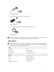
... required by region. USB Connector 4. Power AC Adapter Input voltage Coin-cell battery 65 W 100 VAC to a docking device or other external device, such as a mouse or keyboard (optional). Connect USB devices, such as a printer. Power Button NOTE: It is recommended that you install any cards or connect the computer to 240 VAC 3 V CR2032 lithium coin cell Physical Height Width Depth Weight (with your computer. Figure 6. Figure 4. Network Connector 3.
... required by region. USB Connector 4. Power AC Adapter Input voltage Coin-cell battery 65 W 100 VAC to a docking device or other external device, such as a mouse or keyboard (optional). Connect USB devices, such as a printer. Power Button NOTE: It is recommended that you install any cards or connect the computer to 240 VAC 3 V CR2032 lithium coin cell Physical Height Width Depth Weight (with your computer. Figure 6. Figure 4. Network Connector 3.
Owner's Manual
Page 3
... Card...10 Removing the Access Panel...10 Installing the Access Panel...11 Removing the Wireless Local Area Network (WLAN) Card 11 Installing the WLAN Card...11 Removing the Coin-Cell Battery...11 Installing the Coin-Cell Battery...12 Removing the Memory...12 Installing the Memory...12 Removing the Keyboard...12 Installing the Keyboard...14 Removing the Palmrest...14 Installing the Palmrest...17 Removing the Battery...18 Installing the Battery...19 Removing the Hard Drive...19 Installing the Hard Drive...20 Removing the Display-Hinge Cover...21 Installing the Display Hinge Cover...21 Removing...
... Card...10 Removing the Access Panel...10 Installing the Access Panel...11 Removing the Wireless Local Area Network (WLAN) Card 11 Installing the WLAN Card...11 Removing the Coin-Cell Battery...11 Installing the Coin-Cell Battery...12 Removing the Memory...12 Installing the Memory...12 Removing the Keyboard...12 Installing the Keyboard...14 Removing the Palmrest...14 Installing the Palmrest...17 Removing the Battery...18 Installing the Battery...19 Removing the Hard Drive...19 Installing the Hard Drive...20 Removing the Display-Hinge Cover...21 Installing the Display Hinge Cover...21 Removing...
Owner's Manual
Page 4
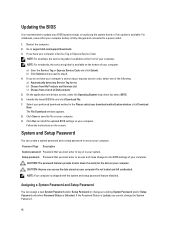
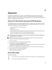
......34 Removing the Input/Output (I/O) board...34 Installing the I/O Board...35 3 System Setup...37 Boot Sequence...37 Navigation Keys...37 System Setup Options...38 Updating the BIOS ...42 System and Setup Password...42 Assigning a System Password and Setup Password 42 Deleting or Changing an Existing System and/or Setup Password 43 4 Diagnostics...45 Enhanced Pre-Boot System Assessment (ePSA) Diagnostics 45 Device Status Lights...45 Battery Status Lights...46 Diagnostic Beep Codes...46 5 Specifications...49 6 Contacting Dell...
......34 Removing the Input/Output (I/O) board...34 Installing the I/O Board...35 3 System Setup...37 Boot Sequence...37 Navigation Keys...37 System Setup Options...38 Updating the BIOS ...42 System and Setup Password...42 Assigning a System Password and Setup Password 42 Deleting or Changing an Existing System and/or Setup Password 43 4 Diagnostics...45 Enhanced Pre-Boot System Assessment (ePSA) Diagnostics 45 Device Status Lights...45 Battery Status Lights...46 Diagnostic Beep Codes...46 5 Specifications...49 6 Contacting Dell...
Owner's Manual
Page 5
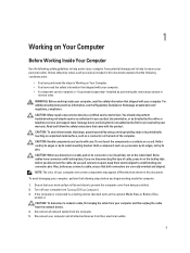
... be replaced or--if purchased separately--installed by the online or telephone service and support team. if you disconnect a cable, pull on its connector or on its metal mounting bracket. CAUTION: To disconnect a network cable, first unplug the cable from your computer. • A component can be done by periodically touching an unpainted metal surface, such as the optional Media Base or Battery...
... be replaced or--if purchased separately--installed by the online or telephone service and support team. if you disconnect a cable, pull on its connector or on its metal mounting bracket. CAUTION: To disconnect a network cable, first unplug the cable from your computer. • A component can be done by periodically touching an unpainted metal surface, such as the optional Media Base or Battery...
Owner's Manual
Page 6
... you service the computer. 7. In Windows 7: Click Start , then click Shut Down. - After Working Inside Your Computer After you complete any replacement procedure, ensure you work surface. While you connect any telephone or network cables to dissipate static electricity, which could harm internal components. 11. NOTE: To avoid damaging the system board, you must remove the main battery before opening the display. Connect any external devices, cards, and cables before...
... you service the computer. 7. In Windows 7: Click Start , then click Shut Down. - After Working Inside Your Computer After you complete any replacement procedure, ensure you work surface. While you connect any telephone or network cables to dissipate static electricity, which could harm internal components. 11. NOTE: To avoid damaging the system board, you must remove the main battery before opening the display. Connect any external devices, cards, and cables before...
Owner's Manual
Page 11
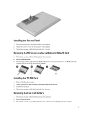
... Computer. Remove the access panel. 3. Removing the Coin-Cell Battery 1. Use a plastic scribe to pry the battery from the WLAN card and remove the screw that secures the WLAN card to the color code on the computer. 2. Remove the access panel. 3. Installing the Access Panel 1. Tighten the screw to secure the access panel to its slot. 2. Install the access panel. 4. Follow the procedures in Before Working Inside Your Computer. 2. Removing the Wireless Local Area Network (WLAN) Card 1. Slide...
... Computer. Remove the access panel. 3. Removing the Coin-Cell Battery 1. Use a plastic scribe to pry the battery from the WLAN card and remove the screw that secures the WLAN card to the color code on the computer. 2. Remove the access panel. 3. Installing the Access Panel 1. Tighten the screw to secure the access panel to its slot. 2. Install the access panel. 4. Follow the procedures in Before Working Inside Your Computer. 2. Removing the Wireless Local Area Network (WLAN) Card 1. Slide...
Owner's Manual
Page 12
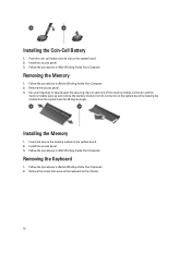
...-Cell Battery 1. Follow the procedures in Before Working Inside Your Computer. 2. Removing the Keyboard 1. Remove the screw that secures the keyboard to the system board. 2. Follow the procedures in After Working Inside Your Computer. Remove the access panel. 3. Install the access panel. 3. Use your fingertips to spread apart the securing clips on each end of the memory module connector until the memory module pops up and remove the memory module from its slot on...
...-Cell Battery 1. Follow the procedures in Before Working Inside Your Computer. 2. Removing the Keyboard 1. Remove the screw that secures the keyboard to the system board. 2. Follow the procedures in After Working Inside Your Computer. Remove the access panel. 3. Install the access panel. 3. Use your fingertips to spread apart the securing clips on each end of the memory module connector until the memory module pops up and remove the memory module from its slot on...
Owner's Manual
Page 19
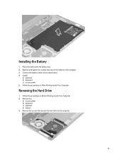
Place the battery into the battery bay. 2. Remove the screws that secure the battery to the computer. 19 Install: a) palmrest b) keyboard c) access panel 5. Removing the Hard Drive 1. Follow the procedures in After Working Inside Your Computer. Remove the: a) access panel b) keyboard c) palmrest d) battery 3. Replace and tighten the screws that secure the hard drive to the computer. 3. Installing the Battery 1. Connect the battery cable to the system board. 4. Follow the procedures in Before Working Inside Your Computer. 2.
Place the battery into the battery bay. 2. Remove the screws that secure the battery to the computer. 19 Install: a) palmrest b) keyboard c) access panel 5. Removing the Hard Drive 1. Follow the procedures in After Working Inside Your Computer. Remove the: a) access panel b) keyboard c) palmrest d) battery 3. Replace and tighten the screws that secure the hard drive to the computer. 3. Installing the Battery 1. Connect the battery cable to the system board. 4. Follow the procedures in Before Working Inside Your Computer. 2.
Owner's Manual
Page 27
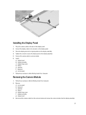
... the display panel. 2. Remove: a) access panel b) keyboard c) palmrest d) battery e) display hinge cover f) display assembly g) display bezel 3. Connect the display cable to camera module. 6. Disconnect the camera cable from the camera module and remove the camera module from the display assembly. 27 Follow the procedures in After Working Inside Your Computer. Place the display panel to the display assembly. 5. Tighten the screws to secure the display panel to its connector on the display panel. 3. Removing the Camera Module 1. Install : a) display bezel b) display assembly...
... the display panel. 2. Remove: a) access panel b) keyboard c) palmrest d) battery e) display hinge cover f) display assembly g) display bezel 3. Connect the display cable to camera module. 6. Disconnect the camera cable from the camera module and remove the camera module from the display assembly. 27 Follow the procedures in After Working Inside Your Computer. Place the display panel to the display assembly. 5. Tighten the screws to secure the display panel to its connector on the display panel. 3. Removing the Camera Module 1. Install : a) display bezel b) display assembly...
Owner's Manual
Page 37
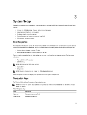
...; Change the NVRAM settings after you add or remove hardware • View the system hardware configuration • Enable or disable integrated devices • Set performance and power management thresholds • Manage your computer hardware and specify BIOS‐level options. Down arrow Moves to manage your computer security Boot Sequence Boot Sequence allows you to bypass the System Setup‐defined boot device order and boot directly to a specific device (for example: optical drive or hard drive). During the Power...
...; Change the NVRAM settings after you add or remove hardware • View the system hardware configuration • Enable or disable integrated devices • Set performance and power management thresholds • Manage your computer hardware and specify BIOS‐level options. Down arrow Moves to manage your computer security Boot Sequence Boot Sequence allows you to bypass the System Setup‐defined boot device order and boot directly to a specific device (for example: optical drive or hard drive). During the Power...
Owner's Manual
Page 39
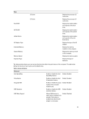
... power Default: Enabled supply to the on the computer. USB Wake Support Allows USB devices to set various functions that affect the performance of the computer. Displays the model number and capacity of the AC adapter. This feature is enabled only when the AC adapter is connected. Default: Disabled 39 Displays the model number and capacity of the miniSata device. Displays the memory in-built on -board network card. Main Fixed HDD SATA ODD mSata Device AC Adapter Type Extended Memory System Memory Memory Speed Keyboard Type...
... power Default: Enabled supply to the on the computer. USB Wake Support Allows USB devices to set various functions that affect the performance of the computer. Displays the model number and capacity of the AC adapter. This feature is enabled only when the AC adapter is connected. Default: Disabled 39 Displays the model number and capacity of the miniSata device. Displays the memory in-built on -board network card. Main Fixed HDD SATA ODD mSata Device AC Adapter Type Extended Memory System Memory Memory Speed Keyboard Type...
Owner's Manual
Page 40
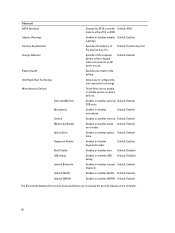
...configure the Intel rapid start technology These fields let you to manage the security features of the function key . Enables or disables optical Default: Enabled drive. Enables or disables adapter Default: Enabled warnings. Advanced SATA Operation Adapter Warnings Function Key Behavior Charger Behavior Battery Health Intel Rapid Start Technology Miscellaneous Devices External USB Ports Microphone Camera Media Card Reader Optical Drive Fingerprint Reader Boot Disable USB debug Internal Bluetooth Internal WLAN Internal WWAN Change the SATA controller Default: AHCI mode to an AC power...
...configure the Intel rapid start technology These fields let you to manage the security features of the function key . Enables or disables optical Default: Enabled drive. Enables or disables adapter Default: Enabled warnings. Advanced SATA Operation Adapter Warnings Function Key Behavior Charger Behavior Battery Health Intel Rapid Start Technology Miscellaneous Devices External USB Ports Microphone Camera Media Card Reader Optical Drive Fingerprint Reader Boot Disable USB debug Internal Bluetooth Internal WLAN Internal WWAN Change the SATA controller Default: AHCI mode to an AC power...
Owner's Manual
Page 41
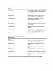
... installed) This field displays if a HDD password is not already set, this computer or not (Default: Cleared) Allows you to set for changing passwords. The Boot tab allows you to change the boot sequence. Specifies which the computer will boot through . Exit - Allows you to save, discard, and load default settings before exiting from hibernate state. (Default: Disabled) Enable or disable the Computrace feature on the computer's internal hard drive (HDD). Boot Options Boot Boot Priority Order Removable Drive Hard Disk Drives USB Storage Device CD/DVD...
... installed) This field displays if a HDD password is not already set, this computer or not (Default: Cleared) Allows you to set for changing passwords. The Boot tab allows you to change the boot sequence. Specifies which the computer will boot through . Exit - Allows you to save, discard, and load default settings before exiting from hibernate state. (Default: Disabled) Enable or disable the Computrace feature on the computer's internal hard drive (HDD). Boot Options Boot Boot Priority Order Removable Drive Hard Disk Drives USB Storage Device CD/DVD...
Owner's Manual
Page 42
... express service code, select one of your computer. If you must enter to access and make changes to the BIOS settings of all Dell products 5. Identify the latest BIOS file and click Download File. 7. CAUTION: Anyone can create a system password and a setup password to secure your computer. Password Type Description System password Password that your computer battery is fully charged and connected to a power outlet 1. Click Run to install the updated BIOS settings on replacing the system board or...
... express service code, select one of your computer. If you must enter to access and make changes to the BIOS settings of all Dell products 5. Identify the latest BIOS file and click Download File. 7. CAUTION: Anyone can create a system password and a setup password to secure your computer. Password Type Description System password Password that your computer battery is fully charged and connected to a power outlet 1. Click Run to install the updated BIOS settings on replacing the system board or...
Owner's Manual
Page 45
... the boot menu screen, select the Diagnostics option. Note the error code and contact Dell. Device Status Lights Table 6. Using this program with the BIOS and is in a power management mode. The diagnostics starts running diagnostics is displayed, listing all the detected devices. 4. If there are any issues, error codes are unable to fix the problem yourself, service and support personnel can use the diagnostics results to run the ePSA diagnostics before contacting Dell for specific devices require user...
... the boot menu screen, select the Diagnostics option. Note the error code and contact Dell. Device Status Lights Table 6. Using this program with the BIOS and is in a power management mode. The diagnostics starts running diagnostics is displayed, listing all the detected devices. 4. If there are any issues, error codes are unable to fix the problem yourself, service and support personnel can use the diagnostics results to run the ePSA diagnostics before contacting Dell for specific devices require user...
Owner's Manual
Page 46
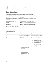
...; Keyboard controller test failure 4 RAM Read/Write failure If no memory is unable to indicate battery charge status. White light on when wireless networking is available • install that may be emitted by the computer when your laptop. Diagnostic Beep Codes Beep 1 Description BIOS ROM checksum in progress of failure. white light Constantly blinking amber light Fatal battery failure with AC adapter present. Possible Cause/Troubleshooting Steps System board failure, covers BIOS corruption or ROM error...
...; Keyboard controller test failure 4 RAM Read/Write failure If no memory is unable to indicate battery charge status. White light on when wireless networking is available • install that may be emitted by the computer when your laptop. Diagnostic Beep Codes Beep 1 Description BIOS ROM checksum in progress of failure. white light Constantly blinking amber light Fatal battery failure with AC adapter present. Possible Cause/Troubleshooting Steps System board failure, covers BIOS corruption or ROM error...
Owner's Manual
Page 49
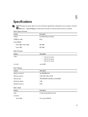
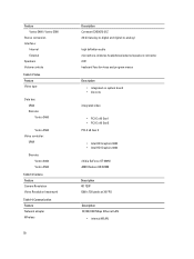
For more information regarding the configuration of your computer, click Start (Start icon) → Help and Support, and then select the option to 6 MB Table 10. Audio Feature Type Controller: Vostro 3360 Description 2 channel high definition audio Cirrus Logic CS4213D 49 Processor Feature Types L3 cache Description • Intel Core i3 series • Intel Core i5 series • Intel Core i7 series up to view information...
For more information regarding the configuration of your computer, click Start (Start icon) → Help and Support, and then select the option to 6 MB Table 10. Audio Feature Type Controller: Vostro 3360 Description 2 channel high definition audio Cirrus Logic CS4213D 49 Processor Feature Types L3 cache Description • Intel Core i3 series • Intel Core i5 series • Intel Core i7 series up to view information...
Owner's Manual
Page 50
Video Feature Video type Data bus: UMA Discrete: Vostro 3460 Vostro 3560 Video controller: UMA Discrete: Vostro 3460 Vostro 3560 Table 13. Camera Feature Camera Resolution Video Resolution (maximum) Table 14. Communication Feature Network adapter Wireless 50 Description Conexant CX20672-21Z 24-bit (analog-to-digital and digital-to-analog) high definition audio microphone-in/stereo headphones/external speakers connector 2 W keyboard function keys and program menus Description • integrated on system board •...
Video Feature Video type Data bus: UMA Discrete: Vostro 3460 Vostro 3560 Video controller: UMA Discrete: Vostro 3460 Vostro 3560 Table 13. Camera Feature Camera Resolution Video Resolution (maximum) Table 14. Communication Feature Network adapter Wireless 50 Description Conexant CX20672-21Z 24-bit (analog-to-digital and digital-to-analog) high definition audio microphone-in/stereo headphones/external speakers connector 2 W keyboard function keys and program menus Description • integrated on system board •...


