User Manual
Page 1
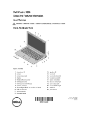
... 19. Dell Vostro 3360 Setup And Features Information About Warnings WARNING: A WARNING indicates a potential for property damage, personal injury, or death. battery status light 18. Front View 1. Windows Mobility Center 6. in-1 media card reader 10. power status light 20. fingerprint reader 13. power button Regulatory Model: P32G Regulatory Type: P32G001 2012 - 01 keyboard 22...
... 19. Dell Vostro 3360 Setup And Features Information About Warnings WARNING: A WARNING indicates a potential for property damage, personal injury, or death. battery status light 18. Front View 1. Windows Mobility Center 6. in-1 media card reader 10. power status light 20. fingerprint reader 13. power button Regulatory Model: P32G Regulatory Type: P32G001 2012 - 01 keyboard 22...
User Manual
Page 3
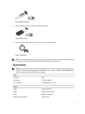
... (with your computer. Power AC Adapter Input voltage Coin-cell battery 65 W 100 VAC to a docking device or other external device, such as a mouse or keyboard (optional). Figure 4. Network Connector 3. Figure 5.
... (with your computer. Power AC Adapter Input voltage Coin-cell battery 65 W 100 VAC to a docking device or other external device, such as a mouse or keyboard (optional). Figure 4. Network Connector 3. Figure 5.
Owner's Manual
Page 3
... Card...11 Removing the Coin-Cell Battery...11 Installing the Coin-Cell Battery...12 Removing the Memory...12 Installing the Memory...12 Removing the Keyboard...12 Installing the Keyboard...14 Removing the Palmrest...14 Installing the Palmrest...17 Removing the Battery...18 Installing the Battery...19 Removing the Hard Drive...19 Installing...
... Card...11 Removing the Coin-Cell Battery...11 Installing the Coin-Cell Battery...12 Removing the Memory...12 Installing the Memory...12 Removing the Keyboard...12 Installing the Keyboard...14 Removing the Palmrest...14 Installing the Palmrest...17 Removing the Battery...18 Installing the Battery...19 Removing the Hard Drive...19 Installing...
Owner's Manual
Page 12
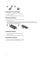
... slot on the system board by drawing the module from the system board at 45-degree angle. Remove the screw that secures the keyboard to the system board. 2. Installing the Memory 1. Push the coin-call battery into its connector on the system board. 2. Removing the... Keyboard 1. Removing the Memory 1. Install the access panel. 3. Follow the procedures in After Working Inside Your Computer. Insert and secure the memory module to the...
... slot on the system board by drawing the module from the system board at 45-degree angle. Remove the screw that secures the keyboard to the system board. 2. Installing the Memory 1. Push the coin-call battery into its connector on the system board. 2. Removing the... Keyboard 1. Removing the Memory 1. Install the access panel. 3. Follow the procedures in After Working Inside Your Computer. Insert and secure the memory module to the...
Owner's Manual
Page 13
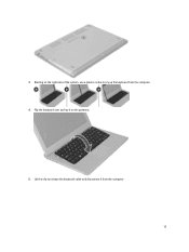
Starting on the palmrest. 5. Lift the clip to pry up the keyboard from the computer. 13 Flip the keyboard over and lay it on the right side of the system, use a plastic scribe to release the keyboard cable and disconnect it from the computer. 4. 3.
Starting on the palmrest. 5. Lift the clip to pry up the keyboard from the computer. 13 Flip the keyboard over and lay it on the right side of the system, use a plastic scribe to release the keyboard cable and disconnect it from the computer. 4. 3.
Owner's Manual
Page 14
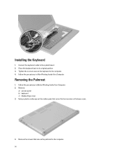
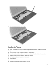
Place the keyboard back to the computer. 4. Tighten the screw to secure the keyboard to its original position. 3. Using a plastic scribe pry out the rubber pads that secure the palmrest to the system board. 2. Removing the Palmrest 1. Remove: a) access panel b) keyboard c) display hinge cover 3. Connect the keyboard cable to the computer. 14 Follow the procedures in Before Working Inside Your Computer. 2. Follow the procedures in After Working Inside Your Computer. Remove the screws that cover the front screws on the base cover. 4. Installing the Keyboard 1.
Place the keyboard back to the computer. 4. Tighten the screw to secure the keyboard to its original position. 3. Using a plastic scribe pry out the rubber pads that secure the palmrest to the system board. 2. Removing the Palmrest 1. Remove: a) access panel b) keyboard c) display hinge cover 3. Connect the keyboard cable to the computer. 14 Follow the procedures in Before Working Inside Your Computer. 2. Follow the procedures in After Working Inside Your Computer. Remove the screws that cover the front screws on the base cover. 4. Installing the Keyboard 1.
Owner's Manual
Page 17
... downwards on the palmrest to cover the screws on the computer. 2. Lift the palmrest up and away from the edges of the computer. 6. Install the keyboard. 8. Tighten the screws to secure the palmrest to the system board. 4. 9.
... downwards on the palmrest to cover the screws on the computer. 2. Lift the palmrest up and away from the edges of the computer. 6. Install the keyboard. 8. Tighten the screws to secure the palmrest to the system board. 4. 9.
Owner's Manual
Page 18
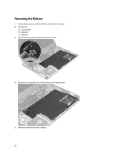
Follow the procedures in Before Working Inside Your Computer. 2. Disconnect the battery cable from the computer. 18 Remove the screws that secure the battery to the system board. 5. Removing the Battery 1. Remove the: a) access panel b) keyboard c) palmrest 3. Remove the battery from the system board. 4.
Follow the procedures in Before Working Inside Your Computer. 2. Disconnect the battery cable from the computer. 18 Remove the screws that secure the battery to the system board. 5. Removing the Battery 1. Remove the: a) access panel b) keyboard c) palmrest 3. Remove the battery from the system board. 4.
Owner's Manual
Page 19
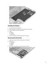
Follow the procedures in Before Working Inside Your Computer. 2. Remove the: a) access panel b) keyboard c) palmrest d) battery 3. Remove the screws that secure the battery to the computer. 19 Replace and tighten the screws that secure the hard drive to the computer. 3. Removing the Hard Drive 1. Connect the battery cable to the system board. 4. Install: a) palmrest b) keyboard c) access panel 5. Place the battery into the battery bay. 2. Installing the Battery 1. Follow the procedures in After Working Inside Your Computer.
Follow the procedures in Before Working Inside Your Computer. 2. Remove the: a) access panel b) keyboard c) palmrest d) battery 3. Remove the screws that secure the battery to the computer. 19 Replace and tighten the screws that secure the hard drive to the computer. 3. Removing the Hard Drive 1. Connect the battery cable to the system board. 4. Install: a) palmrest b) keyboard c) access panel 5. Place the battery into the battery bay. 2. Installing the Battery 1. Follow the procedures in After Working Inside Your Computer.
Owner's Manual
Page 20
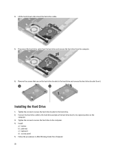
... to disconnect the hard-drive cable. 5. Tighten the screws to secure the hard drive bracket to its original position on the computer. 3. Install: a) battery b) palmrest c) keyboard d) access panel 5. Installing the Hard Drive 1. Follow the procedures in After Working Inside Your Computer. 20 4. Connect the hard drive cable to the hard drive...
... to disconnect the hard-drive cable. 5. Tighten the screws to secure the hard drive bracket to its original position on the computer. 3. Install: a) battery b) palmrest c) keyboard d) access panel 5. Installing the Hard Drive 1. Follow the procedures in After Working Inside Your Computer. 20 4. Connect the hard drive cable to the hard drive...
Owner's Manual
Page 22
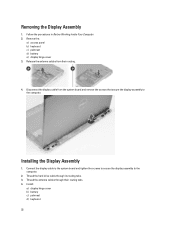
... board and tighten the screws to secure the display assembly to the computer. Install : a) display hinge cover b) battery c) palmrest d) keyboard 22 Installing the Display Assembly 1. Removing the Display Assembly 1. Remove the: a) access panel b) keyboard c) palmrest d) battery e) display hinge cover 3. Thread the antenna cables through its routing tabs. 3. Thread the hard drive cable...
... board and tighten the screws to secure the display assembly to the computer. Install : a) display hinge cover b) battery c) palmrest d) keyboard 22 Installing the Display Assembly 1. Removing the Display Assembly 1. Remove the: a) access panel b) keyboard c) palmrest d) battery e) display hinge cover 3. Thread the antenna cables through its routing tabs. 3. Thread the hard drive cable...
Owner's Manual
Page 23
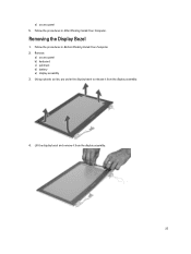
Removing the Display Bezel 1. Remove: a) access panel b) keyboard c) palmrest d) battery e) display assembly 3. Lift the display bezel and remove it from the display assembly. 23 Using a plastic scribe, pry under the display bezel to release it from the display assembly. 4. Follow the procedures in Before Working Inside Your Computer. 2. e) access panel 5. Follow the procedures in After Working Inside Your Computer.
Removing the Display Bezel 1. Remove: a) access panel b) keyboard c) palmrest d) battery e) display assembly 3. Lift the display bezel and remove it from the display assembly. 23 Using a plastic scribe, pry under the display bezel to release it from the display assembly. 4. Follow the procedures in Before Working Inside Your Computer. 2. e) access panel 5. Follow the procedures in After Working Inside Your Computer.
Owner's Manual
Page 24
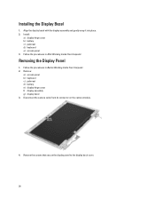
... panel 3. Follow the procedures in After Working Inside Your Computer. Disconnect the camera cable from its connector on the camera module. 4. Remove: a) access panel b) keyboard c) palmrest d) battery e) display hinge cover f) display assembly g) display bezel 3. Installing the Display Bezel 1. Remove the screws that secure the display panel to the display back ...
... panel 3. Follow the procedures in After Working Inside Your Computer. Disconnect the camera cable from its connector on the camera module. 4. Remove: a) access panel b) keyboard c) palmrest d) battery e) display hinge cover f) display assembly g) display bezel 3. Installing the Display Bezel 1. Remove the screws that secure the display panel to the display back ...
Owner's Manual
Page 27
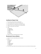
... the display panel to camera module. 6. Install : a) display bezel b) display assembly c) display hinge cover d) battery e) palmrest f) keyboard g) access panel 7. Installing the Display Panel 1. Removing the Camera Module 1. Follow the procedures in After Working Inside Your Computer. Follow the...Disconnect the camera cable from the camera module and remove the camera module from the display assembly. 27 Remove: a) access panel b) keyboard c) palmrest d) battery e) display hinge cover f) display assembly g) display bezel 3. Connect the display cable to its connector on the...
... the display panel to camera module. 6. Install : a) display bezel b) display assembly c) display hinge cover d) battery e) palmrest f) keyboard g) access panel 7. Installing the Display Panel 1. Removing the Camera Module 1. Follow the procedures in After Working Inside Your Computer. Follow the...Disconnect the camera cable from the camera module and remove the camera module from the display assembly. 27 Remove: a) access panel b) keyboard c) palmrest d) battery e) display hinge cover f) display assembly g) display bezel 3. Connect the display cable to its connector on the...
Owner's Manual
Page 28
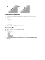
... the camera cable to the camera module and place the camera module to the computer. Install : a) display bezel b) display assembly c) display hinge cover d) battery e) palmrest f) keyboard g) access panel 3. Follow the procedures in Before Working Inside Your Computer. 2. Then, lift the fan and disconnect the fan cable from the system board. 28...
... the camera cable to the camera module and place the camera module to the computer. Install : a) display bezel b) display assembly c) display hinge cover d) battery e) palmrest f) keyboard g) access panel 3. Follow the procedures in Before Working Inside Your Computer. 2. Then, lift the fan and disconnect the fan cable from the system board. 28...
Owner's Manual
Page 29
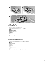
Remove: a) access panel b) keyboard c) palmrest d) display hinge cover e) display assembly f) fan 3. Install : a) display assembly b) display hinge cover c) battery d) palmrest e) keyboard f) access panel 4. Follow the procedures in Before Working Inside Your Computer. 2. Tighten the screws to secure the fan to the system board. 2. Connect the fan cable to the computer. 3. Installing the Fan 1. Follow the procedures in After Working Inside Your Computer. Disconnect the I/O cable from the I/O daughter board. 29 Removing the System Board 1.
Remove: a) access panel b) keyboard c) palmrest d) display hinge cover e) display assembly f) fan 3. Install : a) display assembly b) display hinge cover c) battery d) palmrest e) keyboard f) access panel 4. Follow the procedures in Before Working Inside Your Computer. 2. Tighten the screws to secure the fan to the system board. 2. Connect the fan cable to the computer. 3. Installing the Fan 1. Follow the procedures in After Working Inside Your Computer. Disconnect the I/O cable from the I/O daughter board. 29 Removing the System Board 1.
Owner's Manual
Page 31
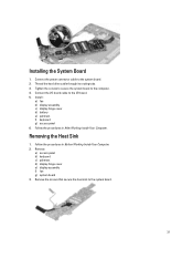
...the screws to secure the system board to the system board. 31 Removing the Heat Sink 1. Remove: a) access panel b) keyboard c) palmrest d) display hinge cover e) display assembly f) fan g) system board 3. Thread the hard drive cable through its routing ...2. Follow the procedures in After Working Inside Your Computer. Install : a) fan b) display assembly c) display hinge cover d) battery e) palmrest f) keyboard g) access panel 6. Follow the procedures in Before Working Inside Your Computer. 2. Connect the power connector cable to the I/O board. 5. Installing the System Board ...
...the screws to secure the system board to the system board. 31 Removing the Heat Sink 1. Remove: a) access panel b) keyboard c) palmrest d) display hinge cover e) display assembly f) fan g) system board 3. Thread the hard drive cable through its routing ...2. Follow the procedures in After Working Inside Your Computer. Install : a) fan b) display assembly c) display hinge cover d) battery e) palmrest f) keyboard g) access panel 6. Follow the procedures in Before Working Inside Your Computer. 2. Connect the power connector cable to the I/O board. 5. Installing the System Board ...
Owner's Manual
Page 32
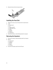
Tighten the screws to secure the heat sink to the system board. 2. Follow the procedures in Before Working Inside Your Computer. 2. Follow the procedures in After Working Inside Your Computer. Remove: a) access panel b) keyboard c) palmrest d) battery e) hard drive 3. Disconnect the speaker cable from the system board, Installing the Heat Sink 1. Install : a) system board b) fan c) display assembly d) display hinge cover e) battery f) palmrest g) keyboard h) access panel 3. Remove the heat sink from the I/O board. 32 Removing the Speakers 1. 4.
Tighten the screws to secure the heat sink to the system board. 2. Follow the procedures in Before Working Inside Your Computer. 2. Follow the procedures in After Working Inside Your Computer. Remove: a) access panel b) keyboard c) palmrest d) battery e) hard drive 3. Disconnect the speaker cable from the system board, Installing the Heat Sink 1. Install : a) system board b) fan c) display assembly d) display hinge cover e) battery f) palmrest g) keyboard h) access panel 3. Remove the heat sink from the I/O board. 32 Removing the Speakers 1. 4.
Owner's Manual
Page 33
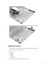
4. Installing the Speakers 1. Install : a) hard drive b) battery c) palmrest d) keyboard e) access panel 4. Release the speaker cables from their routing and remove the speakers from the computer. Place the speakers on the computer and thread the speakers cable through the routing tabs. 2. Connect the speaker cable to the I/O board 3. Follow the procedures in After Working Inside Your Computer. 33
4. Installing the Speakers 1. Install : a) hard drive b) battery c) palmrest d) keyboard e) access panel 4. Release the speaker cables from their routing and remove the speakers from the computer. Place the speakers on the computer and thread the speakers cable through the routing tabs. 2. Connect the speaker cable to the I/O board 3. Follow the procedures in After Working Inside Your Computer. 33

Owner's Manual
Page 34
... d) battery e) display hinge cover f) display assembly g) fan h) system board 3. Install : a) system board b) fan c) display assembly d) display hinge cover e) battery f) palmrest g) keyboard h) access panel 3. Disconnect the speaker cable and the I /O) board 1. Tighten the screw to secure the power connector to the computer and remove the power connector ...
... d) battery e) display hinge cover f) display assembly g) fan h) system board 3. Install : a) system board b) fan c) display assembly d) display hinge cover e) battery f) palmrest g) keyboard h) access panel 3. Disconnect the speaker cable and the I /O) board 1. Tighten the screw to secure the power connector to the computer and remove the power connector ...


