Setup and Features Information Tech Sheet
Page 5
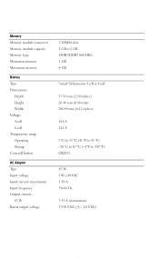
Memory Memory module connector Memory module capacity Memory type: Minimum memory Maximum memory Battery Type Dimensions: Depth Height Width Voltage: 4-cell 6-cell Temperature range: Operating Storage Coin-cell battery AC Adapter Type Input voltage Input current (maximum) Input frequency Output current: 65 W Rated output voltage 2 DIMM slots 1 GB or 2 GB DDR2/DDR3 800...
Memory Memory module connector Memory module capacity Memory type: Minimum memory Maximum memory Battery Type Dimensions: Depth Height Width Voltage: 4-cell 6-cell Temperature range: Operating Storage Coin-cell battery AC Adapter Type Input voltage Input current (maximum) Input frequency Output current: 65 W Rated output voltage 2 DIMM slots 1 GB or 2 GB DDR2/DDR3 800...
Setup and Features Information Tech Sheet
Page 6
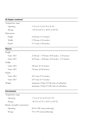
...176;F to 149 °F) 28.20 mm (1.11 inches) 57.90 mm (2.28 inches) 137.2 mm (5.40 inches) Physical Height: Vostro 1014 Vostro 1015 Width: Vostro 1014 Vostro 1015 Depth: Vostro 1014 Vostro 1015 Weight 25.00 mm - 35.60 mm (0.98 inches - 1.40 inches) 26.50 mm - 36.80 mm (1.04 inches -... 1.45 inches) 340 mm (13.38 inches) 376 mm (14.80 inches) 242.5 mm (9.54 inches) 247.9 mm (9.75 inches) minimum 2.30 kg (5.07 lb) with a 6-cell battery...
...176;F to 149 °F) 28.20 mm (1.11 inches) 57.90 mm (2.28 inches) 137.2 mm (5.40 inches) Physical Height: Vostro 1014 Vostro 1015 Width: Vostro 1014 Vostro 1015 Depth: Vostro 1014 Vostro 1015 Weight 25.00 mm - 35.60 mm (0.98 inches - 1.40 inches) 26.50 mm - 36.80 mm (1.04 inches -... 1.45 inches) 340 mm (13.38 inches) 376 mm (14.80 inches) 242.5 mm (9.54 inches) 247.9 mm (9.75 inches) minimum 2.30 kg (5.07 lb) with a 6-cell battery...
Service Manual
Page 2
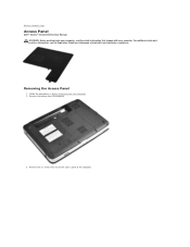
Follow the procedures in Before Working Inside Your Computer. 2. Remove the battery from the computer. 3. Remove the six screws that secure the access panel to Contents Page Access Panel Dell™ Vostro™ 1014/1015 Service Manual WARNING: Before working inside your computer, read the safety information that shipped with your computer. Back to the computer. Removing the Access Panel 1. For additional safety best practices information, see the Regulatory Compliance Homepage at www.dell.com/regulatory_compliance.
Follow the procedures in Before Working Inside Your Computer. 2. Remove the battery from the computer. 3. Remove the six screws that secure the access panel to Contents Page Access Panel Dell™ Vostro™ 1014/1015 Service Manual WARNING: Before working inside your computer, read the safety information that shipped with your computer. Back to the computer. Removing the Access Panel 1. For additional safety best practices information, see the Regulatory Compliance Homepage at www.dell.com/regulatory_compliance.
Service Manual
Page 4
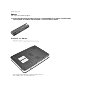
Follow the procedures in Before Working Inside Your Computer. 2. Slide the battery latches apart to Contents Page Battery Dell™ Vostro™ 1014/1015 Service Manual WARNING: Before working inside your computer. Back to the unlock position. For additional safety best practices information, see the Regulatory Compliance Homepage at www.dell.com/regulatory_compliance. Turn the computer upside-down with your computer, read the safety information that shipped with the back of the computer facing you. 3. Removing the Battery 1.
Follow the procedures in Before Working Inside Your Computer. 2. Slide the battery latches apart to Contents Page Battery Dell™ Vostro™ 1014/1015 Service Manual WARNING: Before working inside your computer. Back to the unlock position. For additional safety best practices information, see the Regulatory Compliance Homepage at www.dell.com/regulatory_compliance. Turn the computer upside-down with your computer, read the safety information that shipped with the back of the computer facing you. 3. Removing the Battery 1.
Service Manual
Page 5
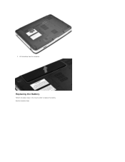
Replacing the Battery Perform the above steps in the reverse order to Contents Page Back to replace the battery. 3. Lift the battery from the computer.
Replacing the Battery Perform the above steps in the reverse order to Contents Page Back to replace the battery. 3. Lift the battery from the computer.
Service Manual
Page 6
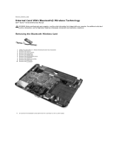
... the WLAN card. 6. Remove the control panel cover. 7. For additional safety best practices information, see the Regulatory Compliance Homepage at www.dell.com/regulatory_compliance. Remove the access panel. 4. Remove the palm rest. 10. Remove the I/O board. 11. Remove the keyboard. 8. ...cable from the connector on the system board. Back to Contents Page Internal Card With Bluetooth® Wireless Technology Dell™ Vostro™ 1014/1015 Service Manual WARNING: Before working inside your computer, read the safety information that shipped with your computer. Removing...
... the WLAN card. 6. Remove the control panel cover. 7. For additional safety best practices information, see the Regulatory Compliance Homepage at www.dell.com/regulatory_compliance. Remove the access panel. 4. Remove the palm rest. 10. Remove the I/O board. 11. Remove the keyboard. 8. ...cable from the connector on the system board. Back to Contents Page Internal Card With Bluetooth® Wireless Technology Dell™ Vostro™ 1014/1015 Service Manual WARNING: Before working inside your computer, read the safety information that shipped with your computer. Removing...
Service Manual
Page 8
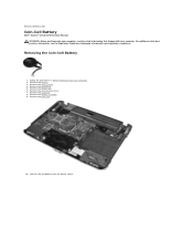
... panel cover. 7. Remove the access panel. 4. For additional safety best practices information, see the Regulatory Compliance Homepage at www.dell.com/regulatory_compliance. Back to Contents Page Coin-Cell Battery Dell™ Vostro™ 1014/1015 Service Manual WARNING: Before working inside your computer, read the safety information that shipped with your computer. Remove the keyboard. 8.
... panel cover. 7. Remove the access panel. 4. For additional safety best practices information, see the Regulatory Compliance Homepage at www.dell.com/regulatory_compliance. Back to Contents Page Coin-Cell Battery Dell™ Vostro™ 1014/1015 Service Manual WARNING: Before working inside your computer, read the safety information that shipped with your computer. Remove the keyboard. 8.
Service Manual
Page 9
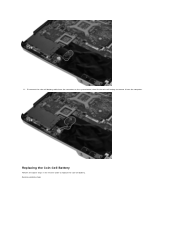
11. Disconnect the coin-cell battery cable from the connector on the system board, then lift the coin-cell battery to replace the coin-cell battery. Replacing the Coin-Cell Battery Perform the above steps in the reverse order to remove it from the computer. Back to Contents Page
11. Disconnect the coin-cell battery cable from the connector on the system board, then lift the coin-cell battery to replace the coin-cell battery. Replacing the Coin-Cell Battery Perform the above steps in the reverse order to remove it from the computer. Back to Contents Page
Service Manual
Page 10
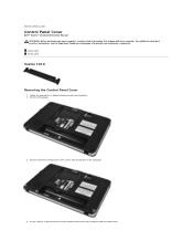
Remove the battery. 3. Vostro 1014 Vostro 1015 Vostro 1014 Removing the Control Panel Cover 1. Follow the procedures in Before Working Inside Your Computer. 2. Remove the three control panel cover screws from the bottom of the computer. 4. Insert a plastic scribe to Contents Page Control Panel Cover Dell™ Vostro™ 1014/1015 Service Manual WARNING: Before working inside the battery well...
Remove the battery. 3. Vostro 1014 Vostro 1015 Vostro 1014 Removing the Control Panel Cover 1. Follow the procedures in Before Working Inside Your Computer. 2. Remove the three control panel cover screws from the bottom of the computer. 4. Insert a plastic scribe to Contents Page Control Panel Cover Dell™ Vostro™ 1014/1015 Service Manual WARNING: Before working inside the battery well...
Service Manual
Page 11
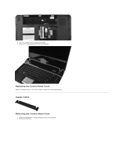
Vostro 1015 Removing the Control Panel Cover 1. Follow the procedures in the reverse order to replace the control panel cover. 5. Remove the control panel cover from the computer. Replacing the Control Panel Cover Perform the above steps in Before Working Inside Your Computer. 2. Remove the battery. Turn the computer over and open the display. 6.
Vostro 1015 Removing the Control Panel Cover 1. Follow the procedures in the reverse order to replace the control panel cover. 5. Remove the control panel cover from the computer. Replacing the Control Panel Cover Perform the above steps in Before Working Inside Your Computer. 2. Remove the battery. Turn the computer over and open the display. 6.
Service Manual
Page 14
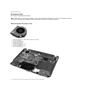
Remove the palm rest. 10. Back to Contents Page Processor Fan Dell™ Vostro™ 1014/1015 Service Manual WARNING: Before working inside your computer, read the safety information that shipped with your computer. Remove the battery. 3. Remove the WLAN card. 6. Remove the control panel cover. 7. Removing the Processor Fan 1. Remove the display assembly. 9. For...
Remove the palm rest. 10. Back to Contents Page Processor Fan Dell™ Vostro™ 1014/1015 Service Manual WARNING: Before working inside your computer, read the safety information that shipped with your computer. Remove the battery. 3. Remove the WLAN card. 6. Remove the control panel cover. 7. Removing the Processor Fan 1. Remove the display assembly. 9. For...
Service Manual
Page 19
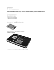
Back to the computer. Remove the battery. 3. Remove the four screws that secure the hard drive assembly to Contents Page Hard Drive Dell™ Vostro™ 1014/1015 Service Manual WARNING: Before working inside your computer, read the safety information that shipped with your computer. Removing the Hard ... Drive Interposer Removing the Hard Drive Assembly 1. For additional safety best practices information, see the Regulatory Compliance Homepage at www.dell.com/regulatory_compliance. Remove the access panel. 4. Follow the procedures in Before Working Inside Your Computer. 2.
Back to the computer. Remove the battery. 3. Remove the four screws that secure the hard drive assembly to Contents Page Hard Drive Dell™ Vostro™ 1014/1015 Service Manual WARNING: Before working inside your computer, read the safety information that shipped with your computer. Removing the Hard ... Drive Interposer Removing the Hard Drive Assembly 1. For additional safety best practices information, see the Regulatory Compliance Homepage at www.dell.com/regulatory_compliance. Remove the access panel. 4. Follow the procedures in Before Working Inside Your Computer. 2.
Service Manual
Page 20
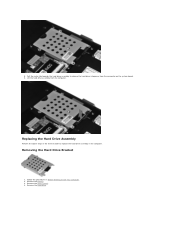
Removing the Hard Drive Bracket 1. Pull the mylar tab towards the hard drive assembly to replace the hard drive assembly in Before Working Inside Your Computer. 2. Replacing the Hard Drive Assembly Perform the above steps in the reverse order to release the hard drive interposer from the computer. Remove the battery. 3. 5. Lift the hard drive assembly from the connector on the system board. 6. Remove the hard drive. Follow the procedures in the computer. Remove the access panel. 4.
Removing the Hard Drive Bracket 1. Pull the mylar tab towards the hard drive assembly to replace the hard drive assembly in Before Working Inside Your Computer. 2. Replacing the Hard Drive Assembly Perform the above steps in the reverse order to release the hard drive interposer from the computer. Remove the battery. 3. 5. Lift the hard drive assembly from the connector on the system board. 6. Remove the hard drive. Follow the procedures in the computer. Remove the access panel. 4.
Service Manual
Page 22
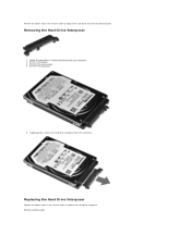
Remove the access panel. 4. Follow the procedures in the reverse order to replace the hard drive interposer. Removing the Hard Drive Interposer 1. Remove the battery. 3. Tugging gently, remove the hard drive interposer from the hard drive. Perform the above steps in the reverse order to replace the hard drive into the hard drive bracket. Replacing the Hard Drive Interposer Perform the above step in Before Working Inside Your Computer. 2. Remove the hard drive. 5. Back to Contents Page
Remove the access panel. 4. Follow the procedures in the reverse order to replace the hard drive interposer. Removing the Hard Drive Interposer 1. Remove the battery. 3. Tugging gently, remove the hard drive interposer from the hard drive. Perform the above steps in the reverse order to replace the hard drive into the hard drive bracket. Replacing the Hard Drive Interposer Perform the above step in Before Working Inside Your Computer. 2. Remove the hard drive. 5. Back to Contents Page
Service Manual
Page 23
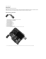
...the battery. 5. Remove the memory modules. 8. Remove the palm rest. 13. Removing the Heat Sink 1. Remove the display assembly. 12. Remove the Bluetooth wireless card. 16. Back to the system board. For additional safety best practices information, see the Regulatory Compliance Homepage at www.dell.... procedures in the illustration below to loosen the four screws that secure the heat sink to Contents Page Heat Sink Dell™ Vostro™ 1014/1015 Service Manual WARNING: Before working inside your computer, read the safety information that shipped with your computer. Remove the...
...the battery. 5. Remove the memory modules. 8. Remove the palm rest. 13. Removing the Heat Sink 1. Remove the display assembly. 12. Remove the Bluetooth wireless card. 16. Back to the system board. For additional safety best practices information, see the Regulatory Compliance Homepage at www.dell.... procedures in the illustration below to loosen the four screws that secure the heat sink to Contents Page Heat Sink Dell™ Vostro™ 1014/1015 Service Manual WARNING: Before working inside your computer, read the safety information that shipped with your computer. Remove the...

Service Manual
Page 25
Removing the I /O board to Contents Page I/O Board Dell™ Vostro™ 1014/1015 Service Manual WARNING: Before working inside your computer. Remove the access panel. 4. Remove the palm rest. 10. Follow the procedures in Before Working Inside Your ... two screws that shipped with your computer, read the safety information that secure the I /O Board 1. Remove the keyboard. 8. Back to the computer chassis. Remove the battery. 3. For additional safety best practices information, see the Regulatory Compliance Homepage at www...
Removing the I /O board to Contents Page I/O Board Dell™ Vostro™ 1014/1015 Service Manual WARNING: Before working inside your computer. Remove the access panel. 4. Remove the palm rest. 10. Follow the procedures in Before Working Inside Your ... two screws that shipped with your computer, read the safety information that secure the I /O Board 1. Remove the keyboard. 8. Back to the computer chassis. Remove the battery. 3. For additional safety best practices information, see the Regulatory Compliance Homepage at www...

Service Manual
Page 27
... control panel cover. 4. Flip the keyboard over and lay it on the palm rest. Remove the battery. 3. Removing the Keyboard 1. For additional safety best practices information, see the Regulatory Compliance Homepage at www.dell.com/regulatory_compliance. Back to Contents Page Keyboard Dell™ Vostro™ 1014/1015 Service Manual WARNING: Before working inside your computer.
... control panel cover. 4. Flip the keyboard over and lay it on the palm rest. Remove the battery. 3. Removing the Keyboard 1. For additional safety best practices information, see the Regulatory Compliance Homepage at www.dell.com/regulatory_compliance. Back to Contents Page Keyboard Dell™ Vostro™ 1014/1015 Service Manual WARNING: Before working inside your computer.
Service Manual
Page 30
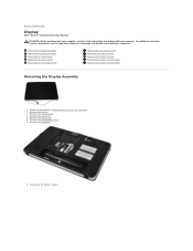
Follow the procedures in Before Working Inside Your Computer. 2. Remove the battery. 3. Disconnect the wireless cables. Remove the WLAN card. 6. Remove the keyboard. 8. Removing the Display Assembly Replacing the Display Assembly Removing ... Assembly 1. Remove the hard drive. 5. Remove the control panel cover. 7. Remove the access panel. 4. Back to Contents Page Display Dell™ Vostro™ 1014/1015 Service Manual WARNING: Before working inside your computer, read the safety information that shipped with your computer. For additional safety best practices information,...
Follow the procedures in Before Working Inside Your Computer. 2. Remove the battery. 3. Disconnect the wireless cables. Remove the WLAN card. 6. Remove the keyboard. 8. Removing the Display Assembly Replacing the Display Assembly Removing ... Assembly 1. Remove the hard drive. 5. Remove the control panel cover. 7. Remove the access panel. 4. Back to Contents Page Display Dell™ Vostro™ 1014/1015 Service Manual WARNING: Before working inside your computer, read the safety information that shipped with your computer. For additional safety best practices information,...
Service Manual
Page 33
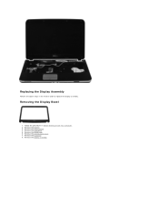
Remove the keyboard. 8. Remove the access panel. 4. Remove the control panel cover. 7. Replacing the Display Assembly Perform the above steps in Before Working Inside Your Computer. 2. Remove the display assembly. Remove the hard drive. 5. Remove the battery. 3. Follow the procedures in the reverse order to replace the display assembly. Remove the WLAN card. 6. Removing the Display Bezel 1.
Remove the keyboard. 8. Remove the access panel. 4. Remove the control panel cover. 7. Replacing the Display Assembly Perform the above steps in Before Working Inside Your Computer. 2. Remove the display assembly. Remove the hard drive. 5. Remove the battery. 3. Follow the procedures in the reverse order to replace the display assembly. Remove the WLAN card. 6. Removing the Display Bezel 1.

Service Manual
Page 35
Remove the display bezel. Remove the control panel cover. 7. Replacing the Display Bezel Perform the above steps in Before Working Inside Your Computer. 2. Remove the battery. 3. Remove the hard drive. 5. Follow the procedures in the reverse order to replace the display bezel into the display assembly. Remove the WLAN card. 6. 11. Remove the access panel. 4. Remove the keyboard. Removing the Display LED Panel 1.
Remove the display bezel. Remove the control panel cover. 7. Replacing the Display Bezel Perform the above steps in Before Working Inside Your Computer. 2. Remove the battery. 3. Remove the hard drive. 5. Follow the procedures in the reverse order to replace the display bezel into the display assembly. Remove the WLAN card. 6. 11. Remove the access panel. 4. Remove the keyboard. Removing the Display LED Panel 1.


