Service Manual
Page 5
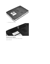
3. Back to replace the battery. Lift the battery from the computer. Replacing the Battery Perform the above steps in the reverse order to Contents Page
3. Back to replace the battery. Lift the battery from the computer. Replacing the Battery Perform the above steps in the reverse order to Contents Page
Service Manual
Page 9
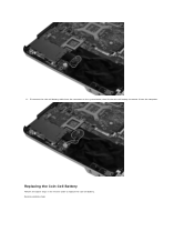
Back to replace the coin-cell battery. Replacing the Coin-Cell Battery Perform the above steps in the reverse order to Contents Page 11. Disconnect the coin-cell battery cable from the connector on the system board, then lift the coin-cell battery to remove it from the computer.
Back to replace the coin-cell battery. Replacing the Coin-Cell Battery Perform the above steps in the reverse order to Contents Page 11. Disconnect the coin-cell battery cable from the connector on the system board, then lift the coin-cell battery to remove it from the computer.
Service Manual
Page 11
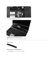
Vostro 1015 Removing the Control Panel Cover 1. Replacing the Control Panel Cover Perform the above steps in Before Working Inside Your Computer. 2. Remove the battery. Follow the procedures in the reverse order to replace the control panel cover. Remove the control panel cover from the computer. 5. Turn the computer over and open the display. 6.
Vostro 1015 Removing the Control Panel Cover 1. Replacing the Control Panel Cover Perform the above steps in Before Working Inside Your Computer. 2. Remove the battery. Follow the procedures in the reverse order to replace the control panel cover. Remove the control panel cover from the computer. 5. Turn the computer over and open the display. 6.
Service Manual
Page 19
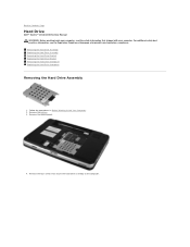
... Drive Bracket Removing the Hard Drive Interposer Replacing the Hard Drive Interposer Removing the Hard Drive Assembly 1. Remove the four screws that shipped with your computer, read the safety information that secure the hard drive assembly to Contents Page Hard Drive Dell™ Vostro™ 1014/1015 Service Manual WARNING: Before working inside your...
... Drive Bracket Removing the Hard Drive Interposer Replacing the Hard Drive Interposer Removing the Hard Drive Assembly 1. Remove the four screws that shipped with your computer, read the safety information that secure the hard drive assembly to Contents Page Hard Drive Dell™ Vostro™ 1014/1015 Service Manual WARNING: Before working inside your...
Service Manual
Page 20
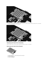
Replacing the Hard Drive Assembly Perform the above steps in the reverse order to release the hard drive interposer from the computer. Remove the access panel. 4. Removing the Hard Drive Bracket 1. Remove the battery. 3. Remove the hard drive. Pull the mylar tab towards the hard drive assembly to replace the hard drive assembly in Before Working Inside Your Computer. 2. 5. Lift the hard drive assembly from the connector on the system board. 6. Follow the procedures in the computer.
Replacing the Hard Drive Assembly Perform the above steps in the reverse order to release the hard drive interposer from the computer. Remove the access panel. 4. Removing the Hard Drive Bracket 1. Remove the battery. 3. Remove the hard drive. Pull the mylar tab towards the hard drive assembly to replace the hard drive assembly in Before Working Inside Your Computer. 2. 5. Lift the hard drive assembly from the connector on the system board. 6. Follow the procedures in the computer.
Service Manual
Page 22
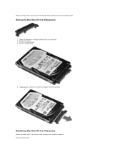
Replacing the Hard Drive Interposer Perform the above step in the reverse order to replace the hard drive into the hard drive bracket. Back to Contents Page Removing the Hard Drive Interposer 1. Perform the above steps in the reverse order to replace the hard drive interposer. Remove the access panel. 4. Tugging gently, remove the hard drive interposer from the hard drive. Remove the battery. 3. Remove the hard drive. 5. Follow the procedures in Before Working Inside Your Computer. 2.
Replacing the Hard Drive Interposer Perform the above step in the reverse order to replace the hard drive into the hard drive bracket. Back to Contents Page Removing the Hard Drive Interposer 1. Perform the above steps in the reverse order to replace the hard drive interposer. Remove the access panel. 4. Tugging gently, remove the hard drive interposer from the hard drive. Remove the battery. 3. Remove the hard drive. 5. Follow the procedures in Before Working Inside Your Computer. 2.
Service Manual
Page 30
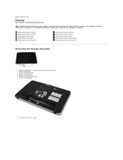
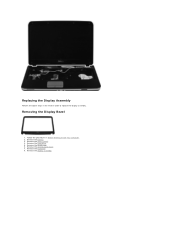
... Display Assembly Removing the Display Bezel Replacing the Display Bezel Removing the LED Display Panel Replacing the LED Display Panel Removing the Display Camera Replacing the Display Camera Removing the Display Inverter Cable Replacing the Display Inverter Cable Removing the Display Assembly 1. ...Back to Contents Page Display Dell™ Vostro™ 1014/1015 Service Manual WARNING: Before working inside your computer, read the safety information that shipped with your computer. Remove the access panel. 4. Remove the WLAN card. 6. Remove the battery. 3. Disconnect the wireless ...
... Display Assembly Removing the Display Bezel Replacing the Display Bezel Removing the LED Display Panel Replacing the LED Display Panel Removing the Display Camera Replacing the Display Camera Removing the Display Inverter Cable Replacing the Display Inverter Cable Removing the Display Assembly 1. ...Back to Contents Page Display Dell™ Vostro™ 1014/1015 Service Manual WARNING: Before working inside your computer, read the safety information that shipped with your computer. Remove the access panel. 4. Remove the WLAN card. 6. Remove the battery. 3. Disconnect the wireless ...
Service Manual
Page 33
Remove the control panel cover. 7. Remove the hard drive. 5. Replacing the Display Assembly Perform the above steps in Before Working Inside Your Computer. 2. Remove the display assembly. Remove the battery. 3. Remove the access panel. 4. Follow the procedures in the reverse order to replace the display assembly. Remove the WLAN card. 6. Remove the keyboard. 8. Removing the Display Bezel 1.
Remove the control panel cover. 7. Remove the hard drive. 5. Replacing the Display Assembly Perform the above steps in Before Working Inside Your Computer. 2. Remove the display assembly. Remove the battery. 3. Remove the access panel. 4. Follow the procedures in the reverse order to replace the display assembly. Remove the WLAN card. 6. Remove the keyboard. 8. Removing the Display Bezel 1.

Service Manual
Page 35
Follow the procedures in the reverse order to replace the display bezel into the display assembly. Remove the control panel cover. 7. Removing the Display LED Panel 1. Remove the battery. 3. Remove the WLAN card. 6. Remove the display bezel. 11. Remove the hard drive. 5. Remove the keyboard. Remove the access panel. 4. Replacing the Display Bezel Perform the above steps in Before Working Inside Your Computer. 2.
Follow the procedures in the reverse order to replace the display bezel into the display assembly. Remove the control panel cover. 7. Removing the Display LED Panel 1. Remove the battery. 3. Remove the WLAN card. 6. Remove the display bezel. 11. Remove the hard drive. 5. Remove the keyboard. Remove the access panel. 4. Replacing the Display Bezel Perform the above steps in Before Working Inside Your Computer. 2.

Service Manual
Page 37
Remove the control panel cover. 7. Remove the hard drive. 5. Remove the display assembly. 9. Replacing the Display LED Panel Perform the above steps in Before Working Inside Your Computer. 2. Remove the display bezel. 10. 12. Remove the WLAN card. 6. Follow the procedures in the reverse to replace the display LED panel. Remove the display LED panel. Lift the display LED panel from the display assembly. Removing the Display Camera 1. Remove the keyboard. 8. Remove the battery. 3. Remove the access panel. 4.
Remove the control panel cover. 7. Remove the hard drive. 5. Remove the display assembly. 9. Replacing the Display LED Panel Perform the above steps in Before Working Inside Your Computer. 2. Remove the display bezel. 10. 12. Remove the WLAN card. 6. Follow the procedures in the reverse to replace the display LED panel. Remove the display LED panel. Lift the display LED panel from the display assembly. Removing the Display Camera 1. Remove the keyboard. 8. Remove the battery. 3. Remove the access panel. 4.

Service Manual
Page 38
... to the display assembly. 12. Remove the battery. 3. Remove the access panel. 4. Remove the WLAN card. 6. Remove the display bezel. 10. Follow the procedures in the reverse order to replace the display camera into its bracket, and from the display assembly. 13. Remove the keyboard. 8. Replacing the Display Camera Perform the above steps...
... to the display assembly. 12. Remove the battery. 3. Remove the access panel. 4. Remove the WLAN card. 6. Remove the display bezel. 10. Follow the procedures in the reverse order to replace the display camera into its bracket, and from the display assembly. 13. Remove the keyboard. 8. Replacing the Display Camera Perform the above steps...
Service Manual
Page 47
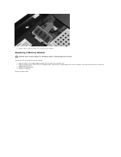
Align the notch in the module edge connector with the tab in the connector slot. 2. Back to remove the second memory module. If you do not feel the click, remove the module and reinstall it clicks into the slot at a 45-degree angle to avoid damaging the connector. 6. Replacing a Memory Module CAUTION: Insert memory modules at a 45-degree angle, and rotate the module down until it . 3. Replace the battery. Slide the module firmly into place. Replace the access panel. 4. Ground yourself and install the memory module: 1. Repeat steps 4 and 5 to Contents Page
Align the notch in the module edge connector with the tab in the connector slot. 2. Back to remove the second memory module. If you do not feel the click, remove the module and reinstall it clicks into the slot at a 45-degree angle to avoid damaging the connector. 6. Replacing a Memory Module CAUTION: Insert memory modules at a 45-degree angle, and rotate the module down until it . 3. Replace the battery. Slide the module firmly into place. Replace the access panel. 4. Ground yourself and install the memory module: 1. Repeat steps 4 and 5 to Contents Page
Service Manual
Page 68
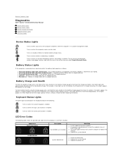
...AC adapter present. If memory is connected to your laptop. Try known good memory from another computer or replace the memory. 4. Replace the system board. 3. Fatal battery failure with steady blue light - l Blue light on when the computer reads or writes data. Each...unsupported, non-Dell AC adapter is in each slot. 3. Battery Charge and Health To check the battery charge, press and release the status button on the battery charge gauge to Contents Page Diagnostics Dell™ Vostro™ 1014/1015 Service Manual Device Status Lights Battery Status Lights Battery Charge and ...
...AC adapter present. If memory is connected to your laptop. Try known good memory from another computer or replace the memory. 4. Replace the system board. 3. Fatal battery failure with steady blue light - l Blue light on when the computer reads or writes data. Each...unsupported, non-Dell AC adapter is in each slot. 3. Battery Charge and Health To check the battery charge, press and release the status button on the battery charge gauge to Contents Page Diagnostics Dell™ Vostro™ 1014/1015 Service Manual Device Status Lights Battery Status Lights Battery Charge and ...
Service Manual
Page 70
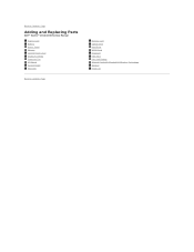
Back to Contents Page Adding and Replacing Parts Dell™ Vostro™ 1014/1015 Service Manual ExpressCard Battery Access Panel Memory Control Panel Cover Display Assembly Processor Fan I/O Board System Board Heat Sink Back to Contents Page Memory Card Optical Drive Hard Drive WLAN Card Keyboard Palm Rest Coin-Cell Battery Internal Card with Bluetooth® Wireless Technology Speaker Processor
Back to Contents Page Adding and Replacing Parts Dell™ Vostro™ 1014/1015 Service Manual ExpressCard Battery Access Panel Memory Control Panel Cover Display Assembly Processor Fan I/O Board System Board Heat Sink Back to Contents Page Memory Card Optical Drive Hard Drive WLAN Card Keyboard Palm Rest Coin-Cell Battery Internal Card with Bluetooth® Wireless Technology Speaker Processor
Service Manual
Page 75
... shipped with your computer. Recommended Tools The procedures in this type of the computer. CAUTION: Many repairs may only be replaced or-if purchased separately-installed by performing the removal procedure in this document may appear differently than shown in this document assumes... To avoid damaging the system board, you must remove the main battery before you are correctly oriented and aligned. Turn the computer top-side up. 9. Working on Your Computer Dell™ Vostro™ 1014/1015 Service Manual Before Working Inside Your Computer Recommended Tools Turning Off Your...
... shipped with your computer. Recommended Tools The procedures in this type of the computer. CAUTION: Many repairs may only be replaced or-if purchased separately-installed by performing the removal procedure in this document may appear differently than shown in this document assumes... To avoid damaging the system board, you must remove the main battery before you are correctly oriented and aligned. Turn the computer top-side up. 9. Working on Your Computer Dell™ Vostro™ 1014/1015 Service Manual Before Working Inside Your Computer Recommended Tools Turning Off Your...

Service Manual
Page 76
... use only the battery designed for this particular Dell computer. Connect any external devices, such as a port replicator, battery slice, or media base, and replace any cards, such as shown below, and then click Shut Down. Connect your computer. Back to your operating system, press and hold the power button for other Dell computers. 1. CAUTION...
... use only the battery designed for this particular Dell computer. Connect any external devices, such as a port replicator, battery slice, or media base, and replace any cards, such as shown below, and then click Shut Down. Connect your computer. Back to your operating system, press and hold the power button for other Dell computers. 1. CAUTION...


