Setup and Features Information Tech Sheet
Page 1
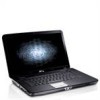
About Warnings WARNING: A WARNING indicates a potential for property damage, personal injury, or death. Dell™ Vostro™ 1014/1015 Setup and Features Information Tech Sheet Front View 123 4 17 16 15 14 13 1 microphone (optional) 3 camera (optional) 5 keyboard status lights November 2010 5 6 9 87 12 11 10 2 camera light (optional) 4 display 6 power button Models: PP38L and PP37L
About Warnings WARNING: A WARNING indicates a potential for property damage, personal injury, or death. Dell™ Vostro™ 1014/1015 Setup and Features Information Tech Sheet Front View 123 4 17 16 15 14 13 1 microphone (optional) 3 camera (optional) 5 keyboard status lights November 2010 5 6 9 87 12 11 10 2 camera light (optional) 4 display 6 power button Models: PP38L and PP37L
Service Manual
Page 1
.../1015 Service Manual Working on Your Computer Adding and Replacing Parts Specifications Diagnostics System Setup Notes, Cautions, and Warnings NOTE: A NOTE indicates important information that helps you purchased a Dell™ n Series computer, any references in this document is subject to Microsoft® Windows® operating systems are not followed. Trademarks used in this material in any manner whatsoever without notice. © 2009 Dell Inc. Microsoft, Windows, Windows Vista...
.../1015 Service Manual Working on Your Computer Adding and Replacing Parts Specifications Diagnostics System Setup Notes, Cautions, and Warnings NOTE: A NOTE indicates important information that helps you purchased a Dell™ n Series computer, any references in this document is subject to Microsoft® Windows® operating systems are not followed. Trademarks used in this material in any manner whatsoever without notice. © 2009 Dell Inc. Microsoft, Windows, Windows Vista...
Service Manual
Page 6
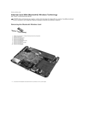
... to Contents Page Internal Card With Bluetooth® Wireless Technology Dell™ Vostro™ 1014/1015 Service Manual WARNING: Before working inside your computer, read the safety information that shipped with your computer. Removing the Bluetooth Wireless Card 1. Remove the control panel cover. 7. Remove the keyboard. 8. Remove the access panel. 4. Remove the battery. 3. Remove the hard drive. 5. Remove the WLAN card. 6. Follow the procedures in Before Working Inside Your Computer. 2. Remove the I/O board. 11. Disconnect the Bluetooth card cable from the connector...
... to Contents Page Internal Card With Bluetooth® Wireless Technology Dell™ Vostro™ 1014/1015 Service Manual WARNING: Before working inside your computer, read the safety information that shipped with your computer. Removing the Bluetooth Wireless Card 1. Remove the control panel cover. 7. Remove the keyboard. 8. Remove the access panel. 4. Remove the battery. 3. Remove the hard drive. 5. Remove the WLAN card. 6. Follow the procedures in Before Working Inside Your Computer. 2. Remove the I/O board. 11. Disconnect the Bluetooth card cable from the connector...
Service Manual
Page 8
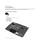
Remove the battery. 3. Remove the control panel cover. 7. Remove the palm rest. 10. Removing the Coin-Cell Battery 1. Remove the hard drive. 5. Pull the coin-cell battery from the plastic sleeve. Back to Contents Page Coin-Cell Battery Dell™ Vostro™ 1014/1015 Service Manual WARNING: Before working inside your computer, read the safety information that shipped with your computer. Remove the access panel. 4. Remove the WLAN card. 6. Remove the display assembly. 9. Follow the procedures in Before...
Remove the battery. 3. Remove the control panel cover. 7. Remove the palm rest. 10. Removing the Coin-Cell Battery 1. Remove the hard drive. 5. Pull the coin-cell battery from the plastic sleeve. Back to Contents Page Coin-Cell Battery Dell™ Vostro™ 1014/1015 Service Manual WARNING: Before working inside your computer, read the safety information that shipped with your computer. Remove the access panel. 4. Remove the WLAN card. 6. Remove the display assembly. 9. Follow the procedures in Before...
Service Manual
Page 14
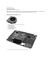
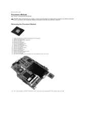
Follow the procedures in Before Working Inside Your Computer. 2. Remove the access panel. 4. Remove the control panel cover. 7. Disconnect the processor fan cable from the connector on the system board. Removing the Processor Fan 1. Remove the hard drive. 5. Remove the WLAN card. 6. Remove the battery. 3. Remove the palm rest. 10. Back to Contents Page Processor Fan Dell™ Vostro™ 1014/1015 Service Manual WARNING: Before working inside your computer, read the safety information that shipped with your computer...
Follow the procedures in Before Working Inside Your Computer. 2. Remove the access panel. 4. Remove the control panel cover. 7. Disconnect the processor fan cable from the connector on the system board. Removing the Processor Fan 1. Remove the hard drive. 5. Remove the WLAN card. 6. Remove the battery. 3. Remove the palm rest. 10. Back to Contents Page Processor Fan Dell™ Vostro™ 1014/1015 Service Manual WARNING: Before working inside your computer, read the safety information that shipped with your computer...
Service Manual
Page 23
...; Vostro™ 1014/1015 Service Manual WARNING: Before working inside your computer, read the safety information that shipped with your computer. Remove the processor fan. 14. Remove the battery. 5. Removing the Heat Sink 1. Remove the hard drive. 7. Remove the WLAN card. 9. Back to the system board. For additional safety best practices information, see the Regulatory Compliance Homepage at www.dell.com/regulatory_compliance. Remove the memory modules. 8. Remove the control panel cover. 10. Remove the Bluetooth wireless card. 16. Remove...
...; Vostro™ 1014/1015 Service Manual WARNING: Before working inside your computer, read the safety information that shipped with your computer. Remove the processor fan. 14. Remove the battery. 5. Removing the Heat Sink 1. Remove the hard drive. 7. Remove the WLAN card. 9. Back to the system board. For additional safety best practices information, see the Regulatory Compliance Homepage at www.dell.com/regulatory_compliance. Remove the memory modules. 8. Remove the control panel cover. 10. Remove the Bluetooth wireless card. 16. Remove...

Service Manual
Page 25
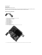
... I/O Board Dell™ Vostro™ 1014/1015 Service Manual WARNING: Before working inside your computer. Remove the access panel. 4. Remove the keyboard. 8. Back to the computer chassis. Remove the WLAN card. 6. Remove the display assembly. 9. Remove the palm rest. 10. Follow the procedures in Before Working Inside Your Computer. 2. Remove the hard drive. 5. Remove the control panel cover. 7. Remove the two screws that shipped with your computer, read the safety information that secure the I /O Board 1. Remove the battery. 3. For...
... I/O Board Dell™ Vostro™ 1014/1015 Service Manual WARNING: Before working inside your computer. Remove the access panel. 4. Remove the keyboard. 8. Back to the computer chassis. Remove the WLAN card. 6. Remove the display assembly. 9. Remove the palm rest. 10. Follow the procedures in Before Working Inside Your Computer. 2. Remove the hard drive. 5. Remove the control panel cover. 7. Remove the two screws that shipped with your computer, read the safety information that secure the I /O Board 1. Remove the battery. 3. For...
Service Manual
Page 30
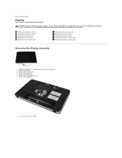
... the keyboard. 8. Remove the battery. 3. Remove the WLAN card. 6. Back to Contents Page Display Dell™ Vostro™ 1014/1015 Service Manual WARNING: Before working inside your computer, read the safety information that shipped with your computer. Remove the control panel cover. 7. Remove the hard drive. 5. Removing the Display Assembly Replacing the Display Assembly Removing the Display Bezel Replacing the Display Bezel Removing the LED Display Panel Replacing the LED Display Panel Removing the Display Camera Replacing the Display Camera Removing the Display Inverter Cable...
... the keyboard. 8. Remove the battery. 3. Remove the WLAN card. 6. Back to Contents Page Display Dell™ Vostro™ 1014/1015 Service Manual WARNING: Before working inside your computer, read the safety information that shipped with your computer. Remove the control panel cover. 7. Remove the hard drive. 5. Removing the Display Assembly Replacing the Display Assembly Removing the Display Bezel Replacing the Display Bezel Removing the LED Display Panel Replacing the LED Display Panel Removing the Display Camera Replacing the Display Camera Removing the Display Inverter Cable...
Service Manual
Page 40
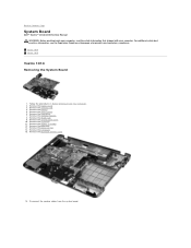
Back to Contents Page System Board Dell™ Vostro™ 1014/1015 Service Manual WARNING: Before working inside your computer, read the safety information that shipped with your computer. Remove the ExpressCard. 3. Remove the control panel cover. 10. Disconnect the speaker cables from the system board. Remove the hard drive. 7. Remove the memory modules. 8. Remove the palm rest. 13. Remove the access panel. 6. Remove the WLAN card. 9. Vostro 1014 Vostro 1015 Vostro 1014 Removing the System Board 1. Remove the battery. 5. Remove the keyboard. 11. For additional safety...
Back to Contents Page System Board Dell™ Vostro™ 1014/1015 Service Manual WARNING: Before working inside your computer, read the safety information that shipped with your computer. Remove the ExpressCard. 3. Remove the control panel cover. 10. Disconnect the speaker cables from the system board. Remove the hard drive. 7. Remove the memory modules. 8. Remove the palm rest. 13. Remove the access panel. 6. Remove the WLAN card. 9. Vostro 1014 Vostro 1015 Vostro 1014 Removing the System Board 1. Remove the battery. 5. Remove the keyboard. 11. For additional safety...
Service Manual
Page 43
Remove the WLAN card. 9. Remove the palm rest. 13. Disconnect the speaker cables from the system board. Remove the access panel. 6. Remove the processor fan. 14. Remove the Bluetooth wireless card. 16. Disconnect the power cable from the system board. 17. Remove the control panel cover. 10. Remove the memory card. 4. Remove the battery. 5. Remove the hard drive. 7. Remove the I/O board. 15. 2. Remove the memory modules. 8. Remove the display assembly. 12. Remove the keyboard. 11. Remove the ExpressCard. 3.
Remove the WLAN card. 9. Remove the palm rest. 13. Disconnect the speaker cables from the system board. Remove the access panel. 6. Remove the processor fan. 14. Remove the Bluetooth wireless card. 16. Disconnect the power cable from the system board. 17. Remove the control panel cover. 10. Remove the memory card. 4. Remove the battery. 5. Remove the hard drive. 7. Remove the I/O board. 15. 2. Remove the memory modules. 8. Remove the display assembly. 12. Remove the keyboard. 11. Remove the ExpressCard. 3.
Service Manual
Page 58
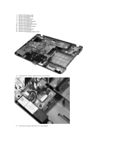
... access panel. 6. Remove the I/O board. 15. Remove the control panel cover. 10. Remove the Bluetooth wireless card. 16. Remove the heat sink. 18. Set aside the computer chassis and place the system board on a clean, dry surface. 19. Remove the WLAN card. 9. Remove the ExpressCard. 3. For additional safety best practices information, see the Regulatory Compliance Homepage at www.dell.com/regulatory_compliance. Remove the memory card (if applicable). 4. Remove the hard drive. 7. Remove the memory modules. 8. Remove the processor fan. 14. Use...
... access panel. 6. Remove the I/O board. 15. Remove the control panel cover. 10. Remove the Bluetooth wireless card. 16. Remove the heat sink. 18. Set aside the computer chassis and place the system board on a clean, dry surface. 19. Remove the WLAN card. 9. Remove the ExpressCard. 3. For additional safety best practices information, see the Regulatory Compliance Homepage at www.dell.com/regulatory_compliance. Remove the memory card (if applicable). 4. Remove the hard drive. 7. Remove the memory modules. 8. Remove the processor fan. 14. Use...
Service Manual
Page 60
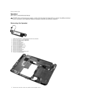
... at www.dell.com/regulatory_compliance. Remove the hard drive. 7. Remove the processor fan. 14. Remove the Bluetooth® wireless card. 16. Remove the battery. 5. Remove the access panel. 6. Remove the palm rest. 13. Remove the keyboard. 11. Follow the procedures in Before Working Inside Your Computer. 2. Remove the memory modules. 8. Remove the I/O board. 15. Back to the computer chassis. Removing the Speaker 1. Remove the ExpressCard (if applicable). 3. Remove the WLAN card. 9. Remove the control panel cover. 10. Remove the display assembly. 12. Remove the system...
... at www.dell.com/regulatory_compliance. Remove the hard drive. 7. Remove the processor fan. 14. Remove the Bluetooth® wireless card. 16. Remove the battery. 5. Remove the access panel. 6. Remove the palm rest. 13. Remove the keyboard. 11. Follow the procedures in Before Working Inside Your Computer. 2. Remove the memory modules. 8. Remove the I/O board. 15. Back to the computer chassis. Removing the Speaker 1. Remove the ExpressCard (if applicable). 3. Remove the WLAN card. 9. Remove the control panel cover. 10. Remove the display assembly. 12. Remove the system...
Service Manual
Page 64
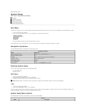
... boot order is restored. Navigation Keystrokes Use the following options appear: Internal hard drive CD/DVD/CD-RW Drive Onboard NIC BIOS Setup Diagnostics 3. Option General Description Turn on (or restart) your computer and press when the keyboard lights first flash. The following keystrokes to navigate the System Setup screens. or right-arrow key, or +/- < > -Remain in the boot menu does not make any changes to the selected device. Turn on (or restart) your 1. When the Dell...
... boot order is restored. Navigation Keystrokes Use the following options appear: Internal hard drive CD/DVD/CD-RW Drive Onboard NIC BIOS Setup Diagnostics 3. Option General Description Turn on (or restart) your computer and press when the keyboard lights first flash. The following keystrokes to navigate the System Setup screens. or right-arrow key, or +/- < > -Remain in the boot menu does not make any changes to the selected device. Turn on (or restart) your 1. When the Dell...

Service Manual
Page 65
Also displays the type of AC adapter connected to enable/disable the following devices: l Internal Modem l Microphone l Camera l Media Card, PC Card and 1394 l External USB Port l ExpressCard Default setting: All enabled Video Option Description LCD Brightness This option (represented by a slider bar for On Battery and On AC) sets the panel brightness when the ambient light sensor is off. Date/Time To remove devices for devices while trying to find an operating system to boot from the sequence of devices specified in this section may...
Also displays the type of AC adapter connected to enable/disable the following devices: l Internal Modem l Microphone l Camera l Media Card, PC Card and 1394 l External USB Port l ExpressCard Default setting: All enabled Video Option Description LCD Brightness This option (represented by a slider bar for On Battery and On AC) sets the panel brightness when the ambient light sensor is off. Date/Time To remove devices for devices while trying to find an operating system to boot from the sequence of devices specified in this section may...

Service Manual
Page 66
... the key. When Setup is on your hard drive's performance and acoustic noise level based on and (2) no effect-Setup works in the operating system. USB emulation is set , change , or delete the password on from an off state when triggered by a special wireless LAN signal. The admin password must be set . Default setting: Enabled Multi Core Support checked This option allows you activate or disable the BIOS module interface of a USB-aware operating system, handles USB devices...
... the key. When Setup is on your hard drive's performance and acoustic noise level based on and (2) no effect-Setup works in the operating system. USB emulation is set , change , or delete the password on from an off state when triggered by a special wireless LAN signal. The admin password must be set . Default setting: Enabled Multi Core Support checked This option allows you activate or disable the BIOS module interface of a USB-aware operating system, handles USB devices...

Service Manual
Page 67
... available wireless devices. Allow the operating system to enable/disable any steps in the boot process. Default setting: Minimal Option Wireless Devices Wireless Description Use the check boxes to control this setting (this works only when the operating system supports Simple Boot Flag). Asset Tag This field allows you would be able to use this screen when users enter the BIOS. l Thorough - If for this feature. Back to enter the Service Tag. Boot quickly unless the BIOS has been updated, memory changed...
... available wireless devices. Allow the operating system to enable/disable any steps in the boot process. Default setting: Minimal Option Wireless Devices Wireless Description Use the check boxes to control this setting (this works only when the operating system supports Simple Boot Flag). Asset Tag This field allows you would be able to use this screen when users enter the BIOS. l Thorough - If for this feature. Back to enter the Service Tag. Boot quickly unless the BIOS has been updated, memory changed...
Service Manual
Page 68
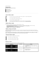
... Bluetooth® wireless technology is connected to an electrical outlet, the battery light operates as follows: l Alternately blinking amber light and blue light - l Light off only the Bluetooth wireless technology function, right-click the icon in each slot. 3. For example, if four lights are installed Next Step 1. Back to Contents Page Diagnostics Dell™ Vostro™ 1014/1015 Service Manual Device Status Lights Battery Status Lights Battery Charge and Health Keyboard Status Lights LED Error Codes Device Status Lights Turns on when you should consider replacing...
... Bluetooth® wireless technology is connected to an electrical outlet, the battery light operates as follows: l Alternately blinking amber light and blue light - l Light off only the Bluetooth wireless technology function, right-click the icon in each slot. 3. For example, if four lights are installed Next Step 1. Back to Contents Page Diagnostics Dell™ Vostro™ 1014/1015 Service Manual Device Status Lights Battery Status Lights Battery Charge and Health Keyboard Status Lights LED Error Codes Device Status Lights Turns on when you should consider replacing...
Service Manual
Page 69
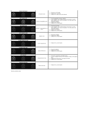
... Storage device error 1. Replace the device that is detected but has errors 1. Install compatible memory modules. 2. Try the other module in the same slot and test. Replace the system board. Video card error 1. Test the other slot with just the hard drive and just the optical drive. 3. Option ROM error 1. Replace the device. 3. Replace the system board. Memory is causing the failure. 4. Reseat the hard drive and optical drive. 2. Replace the memory. 4. Replace the system board. System board error 1. If two modules are installed remove one...
... Storage device error 1. Replace the device that is detected but has errors 1. Install compatible memory modules. 2. Try the other module in the same slot and test. Replace the system board. Video card error 1. Test the other slot with just the hard drive and just the optical drive. 3. Option ROM error 1. Replace the device. 3. Replace the system board. Memory is causing the failure. 4. Reseat the hard drive and optical drive. 2. Replace the memory. 4. Replace the system board. System board error 1. If two modules are installed remove one...

Service Manual
Page 73
...-glare Refresh rate Operating angle Viewing angles Volume controls Horizontal Vertical Pixel pitch Controls Touch Pad X/Y position resolution (graphics table mode) Size (sensor-active area) Width Height Camera Resolution AC Adapter Type Input voltage Input current (maximum) Input frequency Output current 65 W Rated output voltage Dimensions Height Width Depth Temperature range Operating Storage Physical Height: Vostro 1014 Vostro 1015 Width: Vostro 1014 Vostro 1015 Depth: Vostro 1014 Vostro 1015 14" HD...
...-glare Refresh rate Operating angle Viewing angles Volume controls Horizontal Vertical Pixel pitch Controls Touch Pad X/Y position resolution (graphics table mode) Size (sensor-active area) Width Height Camera Resolution AC Adapter Type Input voltage Input current (maximum) Input frequency Output current 65 W Rated output voltage Dimensions Height Width Depth Temperature range Operating Storage Physical Height: Vostro 1014 Vostro 1015 Width: Vostro 1014 Vostro 1015 Depth: Vostro 1014 Vostro 1015 14" HD...
Service Manual
Page 75
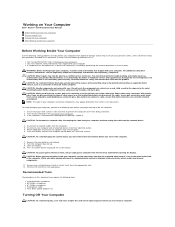
... l Flash BIOS update program CD Turning Off Your Computer CAUTION: To avoid losing data, save and close all open programs before you connect a cable, ensure that shipped with locking tabs; Read and follow the safety instructions that the following safety guidelines to help to ensure your computer. Do not touch the components or contacts on Your Computer Dell™ Vostro™ 1014/1015 Service Manual...
... l Flash BIOS update program CD Turning Off Your Computer CAUTION: To avoid losing data, save and close all open programs before you connect a cable, ensure that shipped with locking tabs; Read and follow the safety instructions that the following safety guidelines to help to ensure your computer. Do not touch the components or contacts on Your Computer Dell™ Vostro™ 1014/1015 Service Manual...


