Getting Started Guide
Page 10
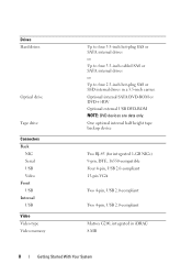
Drives Hard drives Optical drive Tape drive Connectors Back NIC Serial USB Video Front USB Internal USB Video Video type Video memory Up to four 3.5-inch hot-plug SAS or SATA internal drives or Up to four 3.5-inch cabled SAS or SATA internal drives or Up to four 2.5-inch hot-plug SAS or SSD internal drives in iDRAC 8 MB...
Drives Hard drives Optical drive Tape drive Connectors Back NIC Serial USB Video Front USB Internal USB Video Video type Video memory Up to four 3.5-inch hot-plug SAS or SATA internal drives or Up to four 3.5-inch cabled SAS or SATA internal drives or Up to four 2.5-inch hot-plug SAS or SSD internal drives in iDRAC 8 MB...
Hardware Owner's Manual
Page 3
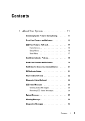
Contents 1 About Your System 11 Accessing System Features During Startup 11 Front-Panel Features and Indicators 12 LCD Panel Features (Optional 14 Home Screen 15 Setup Menu 16 View Menu 17 Hard-Drive Indicator Patterns 18 Back-Panel Features and Indicators 19 Guidelines for Connecting External Devices 21 NIC Indicator Codes 21 Power Indicator Codes 22 Diagnostic Lights (Optional 23 LCD Status Messages 25 Viewing Status Messages 26 Removing LCD Status Messages 26 System Messages 39 Warning Messages 54 Diagnostics Messages 54 Contents 3
Contents 1 About Your System 11 Accessing System Features During Startup 11 Front-Panel Features and Indicators 12 LCD Panel Features (Optional 14 Home Screen 15 Setup Menu 16 View Menu 17 Hard-Drive Indicator Patterns 18 Back-Panel Features and Indicators 19 Guidelines for Connecting External Devices 21 NIC Indicator Codes 21 Power Indicator Codes 22 Diagnostic Lights (Optional 23 LCD Status Messages 25 Viewing Status Messages 26 Removing LCD Status Messages 26 System Messages 39 Warning Messages 54 Diagnostics Messages 54 Contents 3

Hardware Owner's Manual
Page 6
... Installing the Cooling Shroud 89 Hard Drives 90 Removing a Hard-Drive Blank 90 Installing a Hard-Drive Blank 91 Removing a Hot-Swap Hard Drive 91 Installing a Hot-Swap Hard Drive 93 Removing a Hot-Swap Hard Drive From a Hard-Drive Carrier 94 Installing a Hot-Swap Hard Drive Into a Drive Carrier 95 Removing a Cabled Hard Drive 95 Installing a Cabled Hard Drive 97 Removing a Cabled Hard Drive From a Hard-Drive Bracket 98 Optical and Tape Drives 99 Removing an Optical...
... Installing the Cooling Shroud 89 Hard Drives 90 Removing a Hard-Drive Blank 90 Installing a Hard-Drive Blank 91 Removing a Hot-Swap Hard Drive 91 Installing a Hot-Swap Hard Drive 93 Removing a Hot-Swap Hard Drive From a Hard-Drive Carrier 94 Installing a Hot-Swap Hard Drive Into a Drive Carrier 95 Removing a Cabled Hard Drive 95 Installing a Cabled Hard Drive 97 Removing a Cabled Hard Drive From a Hard-Drive Bracket 98 Optical and Tape Drives 99 Removing an Optical...
Hardware Owner's Manual
Page 9
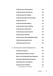
... 153 Troubleshooting System Cooling Problems 154 Troubleshooting a Fan 154 Troubleshooting System Memory 155 Troubleshooting an Internal USB Key 157 Troubleshooting an Optical Drive 158 Troubleshooting a Tape Backup Unit 159 Troubleshooting a Hard Drive 160 Troubleshooting a SAS or SAS RAID Controller . . . . 161 Troubleshooting Expansion Cards 162 Troubleshooting the Processor 163 5 Running the System Diagnostics 165...
... 153 Troubleshooting System Cooling Problems 154 Troubleshooting a Fan 154 Troubleshooting System Memory 155 Troubleshooting an Internal USB Key 157 Troubleshooting an Optical Drive 158 Troubleshooting a Tape Backup Unit 159 Troubleshooting a Hard Drive 160 Troubleshooting a SAS or SAS RAID Controller . . . . 161 Troubleshooting Expansion Cards 162 Troubleshooting the Processor 163 5 Running the System Diagnostics 165...
Hardware Owner's Manual
Page 14
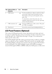
... connectors (2) 10 Front bezel Description Used to troubleshoot software and device driver errors when using the end of a paper clip. Covers the system's front-loading hard drives. The LCD backlight lights blue during normal operating conditions and lights amber to the system. Connects USB devices to indicate an error condition.
... connectors (2) 10 Front bezel Description Used to troubleshoot software and device driver errors when using the end of a paper clip. Covers the system's front-loading hard drives. The LCD backlight lights blue during normal operating conditions and lights amber to the system. Connects USB devices to indicate an error condition.

Hardware Owner's Manual
Page 18
Hard-Drive Indicator Patterns 1 2 1 hard-drive activity indicator (green) 2 hard-drive status indicator (green and amber) Drive-Status Indicator Pattern (RAID Only) Condition Blinks green two times per second Identify drive/preparing for removal Off Drive ready for insertion or removal during this time. Drives are initialized after system power is applied. Blinks green, amber, and off until all hard drives are not ready for insertion or removal NOTE: The drive status indicator remains off Drive predicted failure 18 About Your System
Hard-Drive Indicator Patterns 1 2 1 hard-drive activity indicator (green) 2 hard-drive status indicator (green and amber) Drive-Status Indicator Pattern (RAID Only) Condition Blinks green two times per second Identify drive/preparing for removal Off Drive ready for insertion or removal during this time. Drives are initialized after system power is applied. Blinks green, amber, and off until all hard drives are not ready for insertion or removal NOTE: The drive status indicator remains off Drive predicted failure 18 About Your System
Hardware Owner's Manual
Page 24
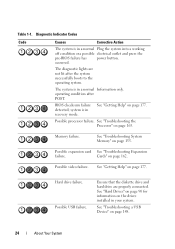
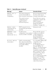
... successfully boots to the operating system. system is in your system. Possible video failure. Possible USB failure. See "Hard Drives" on page 90 for information on the drives installed in a normal Information only. Possible expansion card See "Troubleshooting Expansion failure. Cards" on page 155. The ... on page 177. occurred. See "Troubleshooting a USB Device" on page 177. Possible processor failure. Ensure that the diskette drive and hard drive are not lit after POST. See "Getting Help" on page 148. 24 About Your System Memory failure. Table...
... successfully boots to the operating system. system is in your system. Possible video failure. Possible USB failure. See "Hard Drives" on page 90 for information on the drives installed in a normal Information only. Possible expansion card See "Troubleshooting Expansion failure. Cards" on page 155. The ... on page 177. occurred. See "Troubleshooting a USB Device" on page 177. Possible processor failure. Ensure that the diskette drive and hard drive are not lit after POST. See "Getting Help" on page 148. 24 About Your System Memory failure. Table...
Hardware Owner's Manual
Page 25
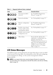
...board resource and/or system board hardware failure. LCD Status Messages The LCD messages consist of brief text messages that the diskette drive, optical drive, and hard drives are properly connected. System board failure. Ensure that refer to boot, press the System ID button for at least five seconds... until an error code appears on page 147 for the appropriate drive installed in your system fails to events recorded in the System Event ...
...board resource and/or system board hardware failure. LCD Status Messages The LCD messages consist of brief text messages that the diskette drive, optical drive, and hard drives are properly connected. System board failure. Ensure that refer to boot, press the System ID button for at least five seconds... until an error code appears on page 147 for the appropriate drive installed in your system fails to events recorded in the System Event ...
Hardware Owner's Manual
Page 34
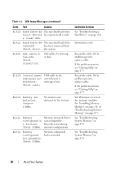
.... If the problem persists, replace cable. Install memory or reseat the memory modules. Table 1-2. E1812 Hard drive ## The specified hard drive removed. the system. E2010 Memory not detected. Error detected during memory configuration. but is detected. Check...155. Check DIMMs. Corrective Actions See "Troubleshooting a Hard Drive" on page 177. If the problem persists, see "Getting Help" on page 155. LCD Status Messages (continued) Code Text Causes E1810 Hard drive ## The specified hard drive fault. Check cable. E2012 Memory Memory configured, ...
.... If the problem persists, replace cable. Install memory or reseat the memory modules. Table 1-2. E1812 Hard drive ## The specified hard drive removed. the system. E2010 Memory not detected. Error detected during memory configuration. but is detected. Check...155. Check DIMMs. Corrective Actions See "Troubleshooting a Hard Drive" on page 177. If the problem persists, see "Getting Help" on page 155. LCD Status Messages (continued) Code Text Causes E1810 Hard drive ## The specified hard drive fault. Check cable. E2012 Memory Memory configured, ...
Hardware Owner's Manual
Page 45
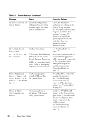
...memory test was terminated by keystroke. A mismatched modules are installed in memory module is installed. Faulty or missing optical drive subsystem, hard drive, or hard-drive subsystem, or no bootable USB key installed. System Messages (continued) Message Memory set check any other system lower for...on setting the order of boot devices. MEMTEST lane failure detected on page 108. Use a bootable USB key, CD, or hard drive. Table 1-3. See "General Memory Module Installation Guidelines" on x No boot device available Causes Corrective Actions The memory frequency If...
...memory test was terminated by keystroke. A mismatched modules are installed in memory module is installed. Faulty or missing optical drive subsystem, hard drive, or hard-drive subsystem, or no bootable USB key installed. System Messages (continued) Message Memory set check any other system lower for...on setting the order of boot devices. MEMTEST lane failure detected on page 108. Use a bootable USB key, CD, or hard drive. Table 1-3. See "General Memory Module Installation Guidelines" on x No boot device available Causes Corrective Actions The memory frequency If...
Hardware Owner's Manual
Page 46
... 162. 46 About Your System See "Troubleshooting Expansion Cards" on page 177. See Figure 6-1 for jumper location. Check the hard-drive configuration settings in System Setup program, or no operating system on hard drive Incorrect configuration settings in the System Setup program. If the problem persists, see "Troubleshooting Expansion Cards" on page 177. System...
... 162. 46 About Your System See "Troubleshooting Expansion Cards" on page 177. See Figure 6-1 for jumper location. Check the hard-drive configuration settings in System Setup program, or no operating system on hard drive Incorrect configuration settings in the System Setup program. If the problem persists, see "Troubleshooting Expansion Cards" on page 177. System...

Hardware Owner's Manual
Page 47
... could not find a SAS backplane, USB, particular sector on page 108. defective. SATA port x device auto-sensing error The drive connected to the specified SATA port. specified SATA port is no device connected Information only. See "General Memory Module Installation Guidelines" ... is properly connected. See "Troubleshooting a USB Device" on page 148, "Troubleshooting an Optical Drive" on page 158, or "Troubleshooting a Hard Drive" on page 160 for the appropriate drive(s) installed in socket. device not found The operating system cannot Replace the optical medium, read ...
... could not find a SAS backplane, USB, particular sector on page 108. defective. SATA port x device auto-sensing error The drive connected to the specified SATA port. specified SATA port is no device connected Information only. See "General Memory Module Installation Guidelines" ... is properly connected. See "Troubleshooting a USB Device" on page 148, "Troubleshooting an Optical Drive" on page 158, or "Troubleshooting a Hard Drive" on page 160 for the appropriate drive(s) installed in socket. device not found The operating system cannot Replace the optical medium, read ...
Hardware Owner's Manual
Page 48
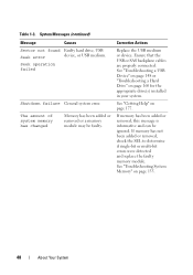
See "Troubleshooting a USB Device" on page 148 or "Troubleshooting a Hard Drive" on page 155. 48 About Your System See "Troubleshooting System Memory" on page 160 for the appropriate drive(s) installed in your system. Seek operation failed Shutdown failure General system error. Corrective Actions Replace the ... or multi-bit errors were detected and replace the faulty memory module. System Messages (continued) Message Causes Sector not found Faulty hard drive, USB Seek error device, or USB medium. If memory has been added or removed, this message is informative and can be...
See "Troubleshooting a USB Device" on page 148 or "Troubleshooting a Hard Drive" on page 155. 48 About Your System See "Troubleshooting System Memory" on page 160 for the appropriate drive(s) installed in your system. Seek operation failed Shutdown failure General system error. Corrective Actions Replace the ... or multi-bit errors were detected and replace the faulty memory module. System Messages (continued) Message Causes Sector not found Faulty hard drive, USB Seek error device, or USB medium. If memory has been added or removed, this message is informative and can be...
Hardware Owner's Manual
Page 54
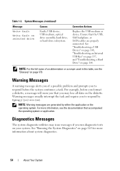
..." on page 148, "Troubleshooting an Internal USB Key" on page 157, and "Troubleshooting a Hard Drive" on your system. Diagnostics Messages The system diagnostic utilities may lose all data on selected drive Causes Faulty USB device, USB medium, optical drive assembly, hard drive, or hard-drive subsystem. See "Running the System Diagnostics" on page 179. NOTE: Warning messages are...
..." on page 148, "Troubleshooting an Internal USB Key" on page 157, and "Troubleshooting a Hard Drive" on your system. Diagnostics Messages The system diagnostic utilities may lose all data on selected drive Causes Faulty USB device, USB medium, optical drive assembly, hard drive, or hard-drive subsystem. See "Running the System Diagnostics" on page 179. NOTE: Warning messages are...
Hardware Owner's Manual
Page 63
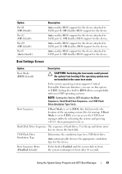
... with non-UEFI operating systems. NOTE: Setting this field is Enabled and the system fails to boot, the system reattempts to SATA port E. Hard-Disk Drive Sequence The sequence of the operating system files for startup. Use the up and down arrow keys to UEFI disables the Boot Sequence..., Hard-Disk Drive Sequence, and USB Flash Drive Emulation Type fields. Auto enables BIOS support for the device attached to BIOS, this option to do so. Boot Sequence If Boot...
... with non-UEFI operating systems. NOTE: Setting this field is Enabled and the system fails to boot, the system reattempts to SATA port E. Hard-Disk Drive Sequence The sequence of the operating system files for startup. Use the up and down arrow keys to UEFI disables the Boot Sequence..., Hard-Disk Drive Sequence, and USB Flash Drive Emulation Type fields. Auto enables BIOS support for the device attached to BIOS, this option to do so. Boot Sequence If Boot...
Hardware Owner's Manual
Page 79
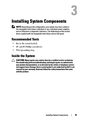
...8226; #1 and #2 Phillips screwdrivers • Wrist grounding strap Inside the System CAUTION: Many repairs may have cabled or hot-swappable hard drives, redundant or non-redundant power supplies, and an LCD panel or diagnostic indicators. Recommended Tools • Key to servicing that came with hot...your product documentation, or as directed by a certified service technician. Read and follow the safety instructions that is not authorized by Dell is not covered by your system may only be done by the online or telephone service and support team. Installing System Components NOTE...
...8226; #1 and #2 Phillips screwdrivers • Wrist grounding strap Inside the System CAUTION: Many repairs may have cabled or hot-swappable hard drives, redundant or non-redundant power supplies, and an LCD panel or diagnostic indicators. Recommended Tools • Key to servicing that came with hot...your product documentation, or as directed by a certified service technician. Read and follow the safety instructions that is not authorized by Dell is not covered by your system may only be done by the online or telephone service and support team. Installing System Components NOTE...

Hardware Owner's Manual
Page 80
Inside the System 1 12 11 10 9 2 3 4 8 5 7 6 1 system cover 3 system cooling fan 5 heat sink and processor 7 SAS backplane 9 optical drive 11 power supplies 2 cooling shroud 4 expansion card slots (5) 6 memory modules (6) 8 hard drives (4) 10 power distribution board 12 power supply bays (2) 80 Installing System Components Figure 3-1.
Inside the System 1 12 11 10 9 2 3 4 8 5 7 6 1 system cover 3 system cooling fan 5 heat sink and processor 7 SAS backplane 9 optical drive 11 power supplies 2 cooling shroud 4 expansion card slots (5) 6 memory modules (6) 8 hard drives (4) 10 power distribution board 12 power supply bays (2) 80 Installing System Components Figure 3-1.
Hardware Owner's Manual
Page 81
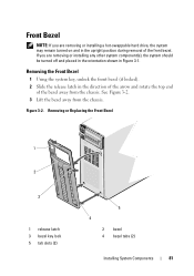
... the direction of the arrow and rotate the top end of the front bezel. Front Bezel NOTE: If you are removing or installing a hot-swappable hard drive, the system may remain turned on and in the upright position during removal of the bezel away from the chassis. Removing or Replacing the Front...
... the direction of the arrow and rotate the top end of the front bezel. Front Bezel NOTE: If you are removing or installing a hot-swappable hard drive, the system may remain turned on and in the upright position during removal of the bezel away from the chassis. Removing or Replacing the Front...
Hardware Owner's Manual
Page 85
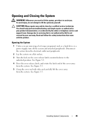
...: Whenever you need to lift the system, get others to the unlocked position. Read and follow the safety instructions that is not authorized by Dell is not covered by the online or telephone service and support team. Opening the System 1 Unless you . See Figure 3-5. 4 Press the ...cover release latch counterclockwise to assist you are removing a hot-swap component such as directed by your product documentation, or as a hard drive or a power supply, turn off the system and attached peripherals. CAUTION: Many repairs may only be done by yourself. Installing System Components 85
...: Whenever you need to lift the system, get others to the unlocked position. Read and follow the safety instructions that is not authorized by Dell is not covered by the online or telephone service and support team. Opening the System 1 Unless you . See Figure 3-5. 4 Press the ...cover release latch counterclockwise to assist you are removing a hot-swap component such as directed by your product documentation, or as a hard drive or a power supply, turn off the system and attached peripherals. CAUTION: Many repairs may only be done by yourself. Installing System Components 85
Hardware Owner's Manual
Page 90
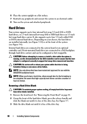
...configured correctly to the system board or an optional controller card. Depending on your system while the drive is free of the drive bay. 90 Installing System Components Hard Drives Your system supports up to be configured as hot-swappable. See "Removing the Front Bezel" on ...to four internal hot-swap 3.5-inch SAS or SATA hard drives, or 2.5-inch internal hot-swap SAS or SSD hard drives in 3.5-inch hot-swap hard-drive carrier. Removing a Hard-Drive Blank CAUTION: To maintain proper system cooling, all empty hard-drive bays must have been tested and approved for the formatting...
...configured correctly to the system board or an optional controller card. Depending on your system while the drive is free of the drive bay. 90 Installing System Components Hard Drives Your system supports up to be configured as hot-swappable. See "Removing the Front Bezel" on ...to four internal hot-swap 3.5-inch SAS or SATA hard drives, or 2.5-inch internal hot-swap SAS or SSD hard drives in 3.5-inch hot-swap hard-drive carrier. Removing a Hard-Drive Blank CAUTION: To maintain proper system cooling, all empty hard-drive bays must have been tested and approved for the formatting...


