Hardware Owner's Manual
Page 8
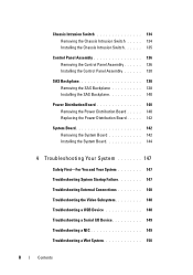
... 134 Removing the Chassis Intrusion Switch . . . . . 134 Installing the Chassis Intrusion Switch 135 Control Panel Assembly 136 Removing the Control Panel Assembly 136 Installing the Control Panel Assembly 138 SAS Backplane 138 Removing the SAS ...
... 134 Removing the Chassis Intrusion Switch . . . . . 134 Installing the Chassis Intrusion Switch 135 Control Panel Assembly 136 Removing the Control Panel Assembly 136 Installing the Control Panel Assembly 138 SAS Backplane 138 Removing the SAS ...

Hardware Owner's Manual
Page 38
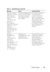
... SEL for 10 seconds or clear the SEL. Reseat DIMM. "##" represents System Memory" on the LCD. I1911 LCD Log Full. I1912 SEL full. removed. Check chassis cover. A maximum of the mirror has had too many errors. LCD Status Messages (continued) Code Text Causes Corrective Actions E2111 SBE log disabled on DIMM...
... SEL for 10 seconds or clear the SEL. Reseat DIMM. "##" represents System Memory" on the LCD. I1911 LCD Log Full. I1912 SEL full. removed. Check chassis cover. A maximum of the mirror has had too many errors. LCD Status Messages (continued) Code Text Causes Corrective Actions E2111 SBE log disabled on DIMM...
Hardware Owner's Manual
Page 40
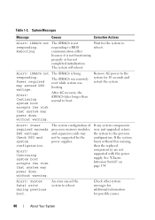
... initialization. If the system boots without warning. The iDRAC6 is hung. Continuing system boot accepts the risk that system may power down without warning. See "Chassis Intrusion Switch" on page 134. Rebooting. The iDRAC6 was remotely reset while system was booting After AC recovery, the iDRAC6 takes longer than normal to...
... initialization. If the system boots without warning. The iDRAC6 is hung. Continuing system boot accepts the risk that system may power down without warning. See "Chassis Intrusion Switch" on page 134. Rebooting. The iDRAC6 was remotely reset while system was booting After AC recovery, the iDRAC6 takes longer than normal to...
Hardware Owner's Manual
Page 50
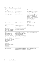
.... If the problem persists, replace the system battery. TPM configuration operation honored. System will reboot and execute the command. SETUP program faulty system battery. See "Chassis Intrusion Switch" on page 57. The system will now reset. This message is pending. Table 1-3. See "Using the System Setup Program and UEFI Boot Manager...
.... If the problem persists, replace the system battery. TPM configuration operation honored. System will reboot and execute the command. SETUP program faulty system battery. See "Chassis Intrusion Switch" on page 57. The system will now reset. This message is pending. Table 1-3. See "Using the System Setup Program and UEFI Boot Manager...
Hardware Owner's Manual
Page 53
... may not be supported by the power supplies. If the problem persists, see "Troubleshooting System Memory" on page 134. Check PSU and system configuration. See "Chassis Intrusion Switch" on page 155. Unsupported memory configuration detected. Ensure that the memory modules are not supported with reduced functionality. Table 1-3. The recommended memory configuration...
... may not be supported by the power supplies. If the problem persists, see "Troubleshooting System Memory" on page 134. Check PSU and system configuration. See "Chassis Intrusion Switch" on page 155. Unsupported memory configuration detected. Ensure that the memory modules are not supported with reduced functionality. Table 1-3. The recommended memory configuration...
Hardware Owner's Manual
Page 81
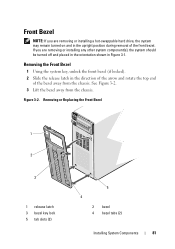
Figure 3-2. See Figure 3-2. 3 Lift the bezel away from the chassis. Removing or Replacing the Front Bezel 1 2 3 1 release latch 3 bezel key lock 5 tab slots (2) 5 4 2 bezel 4 bezel tabs (2) Installing System Components 81 If you are removing or ... or installing a hot-swappable hard drive, the system may remain turned on and in the upright position during removal of the bezel away from the chassis.
Figure 3-2. See Figure 3-2. 3 Lift the bezel away from the chassis. Removing or Replacing the Front Bezel 1 2 3 1 release latch 3 bezel key lock 5 tab slots (2) 5 4 2 bezel 4 bezel tabs (2) Installing System Components 81 If you are removing or ... or installing a hot-swappable hard drive, the system may remain turned on and in the upright position during removal of the bezel away from the chassis.
Hardware Owner's Manual
Page 82
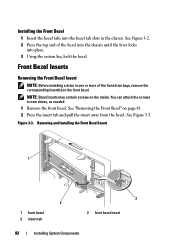
... System Components Installing the Front Bezel 1 Insert the bezel tabs into the bezel tab slots in one or more of the bezel into the chassis until the lever locks into place. 3 Using the system key, lock the bezel. Figure 3-3. See Figure 3-3. Front Bezel Inserts Removing the... Front Bezel Insert NOTE: Before installing a drive in the chassis. See "Removing the Front Bezel" on the inside. See Figure 3-2. 2 Press the top end of the front drive bays, remove the corresponding insert(s) ...
... System Components Installing the Front Bezel 1 Insert the bezel tabs into the bezel tab slots in one or more of the bezel into the chassis until the lever locks into place. 3 Using the system key, lock the bezel. Figure 3-3. See Figure 3-3. Front Bezel Inserts Removing the... Front Bezel Insert NOTE: Before installing a drive in the chassis. See "Removing the Front Bezel" on the inside. See Figure 3-2. 2 Press the top end of the front drive bays, remove the corresponding insert(s) ...
Hardware Owner's Manual
Page 83
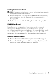
... are essential for airflow efficiency and for EMI protection. See "Removing the Front Bezel" on page 81. 2 Remove the EMI filler panel out of the chassis by pulling firmly on page 82. Removing an EMI Filler Panel 1 Remove the front bezel. Installing System Components 83 Press the insert until the tab...
... are essential for airflow efficiency and for EMI protection. See "Removing the Front Bezel" on page 81. 2 Remove the EMI filler panel out of the chassis by pulling firmly on page 82. Removing an EMI Filler Panel 1 Remove the front bezel. Installing System Components 83 Press the insert until the tab...
Hardware Owner's Manual
Page 84
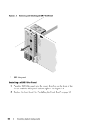
Figure 3-4. See Figure 3-4. 2 Replace the front bezel. See "Installing the Front Bezel" on the front of the chassis until the filler panel locks into place. Removing and Installing an EMI Filler Panel 1 1 EMI filler panel Installing an EMI Filler Panel 1 Push the EMI filler panel into the empty drive bay on page 82. 84 Installing System Components
Figure 3-4. See Figure 3-4. 2 Replace the front bezel. See "Installing the Front Bezel" on the front of the chassis until the filler panel locks into place. Removing and Installing an EMI Filler Panel 1 1 EMI filler panel Installing an EMI Filler Panel 1 Push the EMI filler panel into the empty drive bay on page 82. 84 Installing System Components
Hardware Owner's Manual
Page 86
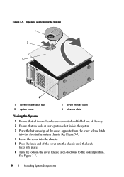
... on the cover release latch clockwise to the locked position. Figure 3-5. Opening and Closing the System 1 2 3 4 1 cover release latch lock 3 system cover 2 cover release latch 4 chassis slots Closing the System 1 Ensure that all internal cables are connected and folded out of the way. 2 Ensure that no tools or extra parts are... left inside the system. 3 Place the bottom edge of the cover into the chassis until the latch locks into the slots in the system chassis. See Figure 3-5. 86 Installing System Components
... on the cover release latch clockwise to the locked position. Figure 3-5. Opening and Closing the System 1 2 3 4 1 cover release latch lock 3 system cover 2 cover release latch 4 chassis slots Closing the System 1 Ensure that all internal cables are connected and folded out of the way. 2 Ensure that no tools or extra parts are... left inside the system. 3 Place the bottom edge of the cover into the chassis until the latch locks into the slots in the system chassis. See Figure 3-5. 86 Installing System Components
Hardware Owner's Manual
Page 87
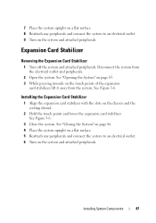
... stabilizer, lift it away from the electrical outlet and peripherals. 2 Open the system. See "Opening the System" on page 85. 3 While pressing inwards on the chassis and the cooling shroud. 2 Hold the touch points and lower the expansion card stabilizer. See "Closing the System" on page 86. 4 Place the system upright...
... stabilizer, lift it away from the electrical outlet and peripherals. 2 Open the system. See "Opening the System" on page 85. 3 While pressing inwards on the chassis and the cooling shroud. 2 Hold the touch points and lower the expansion card stabilizer. See "Closing the System" on page 86. 4 Place the system upright...

Hardware Owner's Manual
Page 88
You should only perform troubleshooting and simple repairs as directed by your warranty. Disconnect the system from the chassis. 88 Installing System Components The cooling shroud directs airflow over the system processor and memory modules. CAUTION: Many repairs may get very hot ... "Opening the System" on the side of data. The system may only be done by a certified service technician. Ensure that is not authorized by Dell is not covered by the online or telephone service and support team. Read and follow the safety instructions that came with the cooling shroud removed...
You should only perform troubleshooting and simple repairs as directed by your warranty. Disconnect the system from the chassis. 88 Installing System Components The cooling shroud directs airflow over the system processor and memory modules. CAUTION: Many repairs may get very hot ... "Opening the System" on the side of data. The system may only be done by a certified service technician. Ensure that is not authorized by Dell is not covered by the online or telephone service and support team. Read and follow the safety instructions that came with the cooling shroud removed...
Hardware Owner's Manual
Page 90
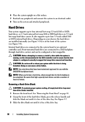
... Drives Your system supports up to remove or install a drive while the system is running, see Figure 3-8). CAUTION: Do not turn off or reboot your chassis, the hard drives are connected to an electrical outlet. 8 Turn on the system and attached peripherals.
... Drives Your system supports up to remove or install a drive while the system is running, see Figure 3-8). CAUTION: Do not turn off or reboot your chassis, the hard drives are connected to an electrical outlet. 8 Turn on the system and attached peripherals.
Hardware Owner's Manual
Page 102
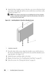
... screws, remove the three shoulder screws from the old drive or the back of the system, align the shoulder screws with the slots in the chassis and slide the drive into the drive bay until the shoulder screws snap into place. See "Installing the Front Bezel" on page 86. 102 Installing...
... screws, remove the three shoulder screws from the old drive or the back of the system, align the shoulder screws with the slots in the chassis and slide the drive into the drive bay until the shoulder screws snap into place. See "Installing the Front Bezel" on page 86. 102 Installing...
Hardware Owner's Manual
Page 103
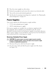
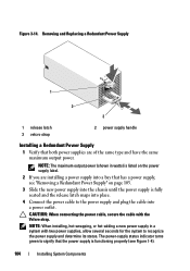
... power load is powered on. 1 Disconnect the power cable from the power supply. 2 Press the release latch and slide the power supply out of the chassis. 11 Place the system upright on a flat surface. 12 Reattach any peripherals and connect the system to maximize efficiency. Removing a Redundant Power Supply CAUTION: The...
... power load is powered on. 1 Disconnect the power cable from the power supply. 2 Press the release latch and slide the power supply out of the chassis. 11 Place the system upright on a flat surface. 12 Reattach any peripherals and connect the system to maximize efficiency. Removing a Redundant Power Supply CAUTION: The...
Hardware Owner's Manual
Page 104
... supply in watts) is listed on page 103. 3 Slide the new power supply into a bay that both power supplies are installing a power supply into the chassis until the power supply is functioning properly (see "Removing a Redundant Power Supply" on the power supply label. 2 If you are of the same type and...
... supply in watts) is listed on page 103. 3 Slide the new power supply into a bay that both power supplies are installing a power supply into the chassis until the power supply is functioning properly (see "Removing a Redundant Power Supply" on the power supply label. 2 If you are of the same type and...
Hardware Owner's Manual
Page 105
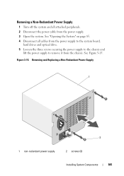
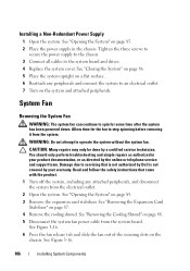
Removing and Replacing a Non-Redundant Power Supply 1 2 1 non-redundant power supply 2 screws (3) Installing System Components 105 See "Opening the System" on page 85. 4 Disconnect all attached peripherals. 2 Disconnect the power cable from the chassis. See Figure 3-15. Removing a Non-Redundant Power Supply 1 Turn off the system and all cables from the power supply to the system board, hard drives and optical drive. 5 Loosen the three screws securing the power supply to the chassis and lift the power supply to remove it from the power supply. 3 Open the system. Figure 3-15.
Removing and Replacing a Non-Redundant Power Supply 1 2 1 non-redundant power supply 2 screws (3) Installing System Components 105 See "Opening the System" on page 85. 4 Disconnect all attached peripherals. 2 Disconnect the power cable from the chassis. See Figure 3-15. Removing a Non-Redundant Power Supply 1 Turn off the system and all cables from the power supply to the system board, hard drives and optical drive. 5 Loosen the three screws securing the power supply to the chassis and lift the power supply to remove it from the power supply. 3 Open the system. Figure 3-15.
Hardware Owner's Manual
Page 106
... Components See "Opening the System" on page 87. 4 Remove the cooling shroud. Tighten the three screws to secure the power supply to the chassis. 3 Connect all cables to operate the system without the system fan. CAUTION: Many repairs may only be done by the online or telephone service...system upright on page 88. 5 Disconnect the system fan power cable from the system. Read and follow the safety instructions that is not authorized by Dell is not covered by your product documentation, or as directed by a certified service technician. See Figure 3-16. 6 Press the fan release tab ...
... Components See "Opening the System" on page 87. 4 Remove the cooling shroud. Tighten the three screws to secure the power supply to the chassis. 3 Connect all cables to operate the system without the system fan. CAUTION: Many repairs may only be done by the online or telephone service...system upright on page 88. 5 Disconnect the system fan power cable from the system. Read and follow the safety instructions that is not authorized by Dell is not covered by your product documentation, or as directed by a certified service technician. See Figure 3-16. 6 Press the fan release tab ...

Hardware Owner's Manual
Page 107
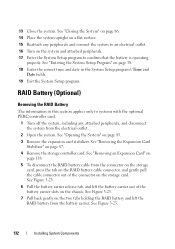
Installing System Components 107 Figure 3-16. Removing the System Fan 1 2 3 4 5 1 touch-point 2 release tab 3 system fan 4 power cable 5 FAN connector on the system board Installing the System Fan 1 Align the tabs on the system fan with the securing slots on the chassis. 2 Slide the system fan into the securing slots until the release tab locks into place.
Installing System Components 107 Figure 3-16. Removing the System Fan 1 2 3 4 5 1 touch-point 2 release tab 3 system fan 4 power cable 5 FAN connector on the system board Installing the System Fan 1 Align the tabs on the system fan with the securing slots on the chassis. 2 Slide the system fan into the securing slots until the release tab locks into place.
Hardware Owner's Manual
Page 132
.... 19 Exit the System Setup program. See "Opening the System" on the storage card. 13 Close the system. See "Removing an Expansion Card" on the chassis. See Figure 3-25. 6 Pull the battery carrier release tab, and lift the battery carrier out of the connector on page 85. 3 Remove the expansion card...
.... 19 Exit the System Setup program. See "Opening the System" on the storage card. 13 Close the system. See "Removing an Expansion Card" on the chassis. See Figure 3-25. 6 Pull the battery carrier release tab, and lift the battery carrier out of the connector on page 85. 3 Remove the expansion card...


