
Information Update
Page 1
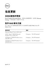
Information Update System Setup Program Update The Error Logging Threshold Mode option is not available in the Memory Settings screen. Software RAID Solutions Software RAID PERC S100 and PERC S300 are not supported ...
Information Update System Setup Program Update The Error Logging Threshold Mode option is not available in the Memory Settings screen. Software RAID Solutions Software RAID PERC S100 and PERC S300 are not supported ...
Information Update
Page 3
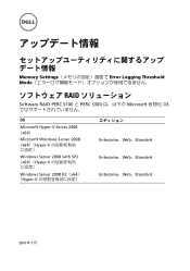
信息更新 Error Logging Threshold Mode Memory Settings 软件 RAID 以下 Microsoft RAID PERC S100 和 PERC S300。 操作系统 Microsoft Hyper-V Server ...
信息更新 Error Logging Threshold Mode Memory Settings 软件 RAID 以下 Microsoft RAID PERC S100 和 PERC S300。 操作系统 Microsoft Hyper-V Server ...
Information Update
Page 9
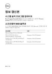
Memory Settings Error Logging Threshold Mode RAID Software RAID PERC S100 と PERC S300 Microsoft 仮想化 OS OS Microsoft Hyper-V Server 2008 (x64) Microsoft Windows Server 2008 (x64)(Hyper-V Windows Server 2008 with SP2 (x64)(Hyper-V Windows Server 2008 R2(x64) (Hyper-V Enterprise、Web、Standard Enterprise、Web、Standard Enterprise、Web、Standard 2010 年 7 月
Memory Settings Error Logging Threshold Mode RAID Software RAID PERC S100 と PERC S300 Microsoft 仮想化 OS OS Microsoft Hyper-V Server 2008 (x64) Microsoft Windows Server 2008 (x64)(Hyper-V Windows Server 2008 with SP2 (x64)(Hyper-V Windows Server 2008 R2(x64) (Hyper-V Enterprise、Web、Standard Enterprise、Web、Standard Enterprise、Web、Standard 2010 年 7 月
Information Update
Page 11
Error Logging Threshold Mode Memory Settings RAID 솔루션 RAID PERC S100 및 PERC S300은 다음 Microsoft Microsoft Hyper-V Server 2008(x64) Microsoft Windows Server 2008(x64)(Hyper-V Windows Server 2008 SP2(x64)(Hyper-V Windows Server 2008 R2(x64)(Hyper-V 버전 Enterprise, Web 및 Standard Enterprise, Web 및 Standard Enterprise, Web 및 Standard 2010 년 7 월
Error Logging Threshold Mode Memory Settings RAID 솔루션 RAID PERC S100 및 PERC S300은 다음 Microsoft Microsoft Hyper-V Server 2008(x64) Microsoft Windows Server 2008(x64)(Hyper-V Windows Server 2008 SP2(x64)(Hyper-V Windows Server 2008 R2(x64)(Hyper-V 버전 Enterprise, Web 및 Standard Enterprise, Web 및 Standard Enterprise, Web 및 Standard 2010 년 7 월
Getting Started Guide
Page 9
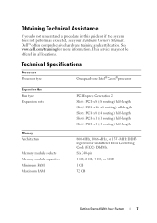
... Slot4: PCIe x1 (x1 routing) half-length Slot5: PCIe x1 (x1 routing) half-length 800-MHz, 1066-MHz, or 1333-MHz DDR3 registered or unbuffered Error Correcting Code (ECC) DIMMs. Six 240-pin 1 GB, 2 GB, 4 GB, or 8 GB 1 GB 32 GB Getting Started With Your System 7 Obtaining Technical Assistance If... you do not understand a procedure in all locations. See www.dell.com/training for more information. This service may not be offered in this guide or if the system does not perform as expected, see your...
... Slot4: PCIe x1 (x1 routing) half-length Slot5: PCIe x1 (x1 routing) half-length 800-MHz, 1066-MHz, or 1333-MHz DDR3 registered or unbuffered Error Correcting Code (ECC) DIMMs. Six 240-pin 1 GB, 2 GB, 4 GB, or 8 GB 1 GB 32 GB Getting Started With Your System 7 Obtaining Technical Assistance If... you do not understand a procedure in all locations. See www.dell.com/training for more information. This service may not be offered in this guide or if the system does not perform as expected, see your...
Hardware Owner's Manual
Page 4
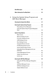
... 55 2 Using the System Setup Program and UEFI Boot Manager 57 Choosing the System Boot Mode 57 Entering the System Setup Program 58 Responding to Error Messages 58 Using the System Setup Program Navigation Keys 58 System Setup Options 59 Main Screen 59 Memory Settings Screen 61 Processor Settings Screen 62...
... 55 2 Using the System Setup Program and UEFI Boot Manager 57 Choosing the System Boot Mode 57 Entering the System Setup Program 58 Responding to Error Messages 58 Using the System Setup Program Navigation Keys 58 System Setup Options 59 Main Screen 59 Memory Settings Screen 61 Processor Settings Screen 62...
Hardware Owner's Manual
Page 13
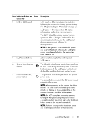
... to the system is on . LCD panel - NOTE: On ACPI-compliant operating systems, turning off . Provides system ID, status information, and system error messages. When the button is pushed, the LCD panel on page 23. See "Diagnostic Lights (Optional)" on the front flashes blue until the button ...LCD lights amber regardless of memory installed in the system. The LCD lights amber when the system needs attention, and the LCD panel displays an error code followed by descriptive text. Item Indicator, Button, or Icon Connector 4 LED or LCD panel 5 LCD menu buttons Description LED panel -...
... to the system is on . LCD panel - NOTE: On ACPI-compliant operating systems, turning off . Provides system ID, status information, and system error messages. When the button is pushed, the LCD panel on page 23. See "Diagnostic Lights (Optional)" on the front flashes blue until the button ...LCD lights amber regardless of memory installed in the system. The LCD lights amber when the system needs attention, and the LCD panel displays an error code followed by descriptive text. Item Indicator, Button, or Icon Connector 4 LED or LCD panel 5 LCD menu buttons Description LED panel -...
Hardware Owner's Manual
Page 14
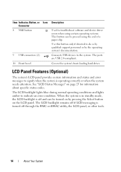
... correctly or when the system needs attention. LCD Panel Features (Optional) The system's LCD panel provides system information and status and error messages to do so by qualified support personnel or by pressing the Select button on page 25 for information about specific status codes.... The LCD backlight lights blue during normal operating conditions and lights amber to troubleshoot software and device driver errors when using certain operating systems. This button can be pressed using the end of a paper clip. When the system is in standby...
... correctly or when the system needs attention. LCD Panel Features (Optional) The system's LCD panel provides system information and status and error messages to do so by qualified support personnel or by pressing the Select button on page 25 for information about specific status codes.... The LCD backlight lights blue during normal operating conditions and lights amber to troubleshoot software and device driver errors when using certain operating systems. This button can be pressed using the end of a paper clip. When the system is in standby...

Hardware Owner's Manual
Page 15
If the system hangs during normal system operation when there are no status messages or errors present. This screen is in standby mode, About Your System 15 During message scrolling: • Press once to increase scrolling speed. • Press again to ...
If the system hangs during normal system operation when there are no status messages or errors present. This screen is in standby mode, About Your System 15 During message scrolling: • Press once to increase scrolling speed. • Press again to ...
Hardware Owner's Manual
Page 16
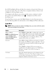
...Home icon. See "LCD Status Messages" on page 25 for information on the Setup and View submenus. Press one of inactivity if there are no error messages. Setup Menu NOTE: When you select an option in this format. This can be displayed on the Home screen. 16 About Your System ... screen. See "View Menu" on the Subnet (Sub), and Gateway (Gtw). To navigate to the Home screen from another menu, continue to display LCD error messages in the SEL. If Static IP is selected, the available fields are available. Select Simple to select the up arrow until the Home icon...
...Home icon. See "LCD Status Messages" on page 25 for information on the Setup and View submenus. Press one of inactivity if there are no error messages. Setup Menu NOTE: When you select an option in this format. This can be displayed on the Home screen. 16 About Your System ... screen. See "View Menu" on the Subnet (Sub), and Gateway (Gtw). To navigate to the Home screen from another menu, continue to display LCD error messages in the SEL. If Static IP is selected, the available fields are available. Select Simple to select the up arrow until the Home icon...
Hardware Owner's Manual
Page 23
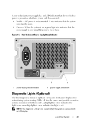
... , a green light also indicates that the power supply is providing DC power to the system. When the system is on the system front panel display error codes during system startup.
... , a green light also indicates that the power supply is providing DC power to the system. When the system is on the system front panel display error codes during system startup.
Hardware Owner's Manual
Page 25
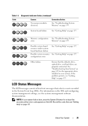
System board failure. See "Troubleshooting Your System" on page 147 for at least five seconds until an error code appears on page 177. LCD Status Messages The LCD messages consist of brief text messages that the diskette drive, optical drive, and hard drives ... system fails to boot, press the System ID button for the appropriate drive installed in the System Event Log (SEL). Memory configuration See "Troubleshooting System error. configuration error. NOTE: If your system. Record the code, then see "Getting Help" on page 177.
System board failure. See "Troubleshooting Your System" on page 147 for at least five seconds until an error code appears on page 177. LCD Status Messages The LCD messages consist of brief text messages that the diskette drive, optical drive, and hard drives ... system fails to boot, press the System ID button for the appropriate drive installed in the System Event Log (SEL). Memory configuration See "Troubleshooting System error. configuration error. NOTE: If your system. Record the code, then see "Getting Help" on page 177.
Hardware Owner's Manual
Page 26
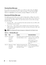
...Clear the SEL - wait for 10 seconds and restart the system. Table 1-2. LCD Status Messages Code Text Causes Corrective Actions E1000 Failsafe voltage error. E1114 Ambient Temp exceeds allowed range. If the problem persists, see "Getting Help" on , the LCD message is automatically removed when that... lose the event history for the system. • Power cycle - Check the system event log Remove AC power to view the error. Press the Select button to remove the message from the electrical outlet; NOTE: The following LCD status messages are displayed in the ...
...Clear the SEL - wait for 10 seconds and restart the system. Table 1-2. LCD Status Messages Code Text Causes Corrective Actions E1000 Failsafe voltage error. E1114 Ambient Temp exceeds allowed range. If the problem persists, see "Getting Help" on , the LCD message is automatically removed when that... lose the event history for the system. • Power cycle - Check the system event log Remove AC power to view the error. Press the Select button to remove the message from the electrical outlet; NOTE: The following LCD status messages are displayed in the ...
Hardware Owner's Manual
Page 28
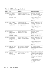
... to the system for 10 seconds and restart the system. E122D Memory One of the on page 177. Check fan. E1410 System Fatal A fatal system error has Error been detected. Remove AC power to the system for 10 seconds and restart the system. See "Troubleshooting the Processor" on page 155. up the...
... to the system for 10 seconds and restart the system. E122D Memory One of the on page 177. Check fan. E1410 System Fatal A fatal system error has Error been detected. Remove AC power to the system for 10 seconds and restart the system. See "Troubleshooting the Processor" on page 155. up the...

Hardware Owner's Manual
Page 29
... Check CPU is out exceeding of acceptable range. E1420 CPU Bus The system BIOS has parity error. reported a processor Power cycle bus parity error. Check temperature range. E141F CPU # protocol error. If the problem persists, see "Getting Help" on page 163. Ensure that the processor ... the system. E1418 CPU # not detected. Table 1-2. CPU heatsink. The system BIOS has reported a processor protocol error. an unsupported See "Troubleshooting the configuration. Processor is missing or bad, Ensure that your system's Getting Started Guide.
... Check CPU is out exceeding of acceptable range. E1420 CPU Bus The system BIOS has parity error. reported a processor Power cycle bus parity error. Check temperature range. E141F CPU # protocol error. If the problem persists, see "Getting Help" on page 163. Ensure that the processor ... the system. E1418 CPU # not detected. Table 1-2. CPU heatsink. The system BIOS has reported a processor protocol error. an unsupported See "Troubleshooting the configuration. Processor is missing or bad, Ensure that your system's Getting Started Guide.
Hardware Owner's Manual
Page 30
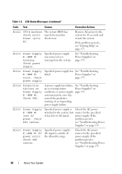
...See "Troubleshooting Power Supplies" on condition, or power supply page 153. Power Supplies" on Power Supply # (### W). communication error has caused the predictive warning of the allowable range. LCD Status Messages (continued) Code Text Causes Corrective Actions E1422 CPU #... machine The system BIOS has check error. power supply. E1618 Predictive failure on error. power supply. Specified power supply's AC input is missing from the system. AC. Check PSU. Check ...
...See "Troubleshooting Power Supplies" on condition, or power supply page 153. Power Supplies" on Power Supply # (### W). communication error has caused the predictive warning of the allowable range. LCD Status Messages (continued) Code Text Causes Corrective Actions E1422 CPU #... machine The system BIOS has check error. power supply. E1618 Predictive failure on error. power supply. Specified power supply's AC input is missing from the system. AC. Check PSU. Check ...
Hardware Owner's Manual
Page 31
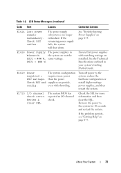
... Messages (continued) Code Text Causes Corrective Actions E1624 Lost power supply redundancy. the system are installed. Table 1-2. The system BIOS has reported an I /O channel check error. E1710 I /O channel check.
... Messages (continued) Code Text Causes Corrective Actions E1624 Lost power supply redundancy. the system are installed. Table 1-2. The system BIOS has reported an I /O channel check error. E1710 I /O channel check.
Hardware Owner's Manual
Page 32
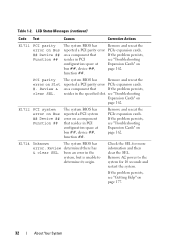
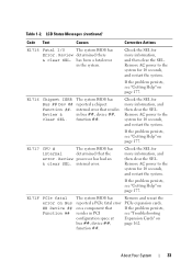
... its origin. Remove and reseat the PCIe expansion cards. PCI parity error on Bus ## Device ## Function ## The system BIOS has Remove and reseat the reported a PCI parity error PCIe expansion cards. been an error in PCI configuration space at Expansion Cards" on page 177. 32 ...About Your System E1712 PCI system error on Bus ## Device ## Function ## The system BIOS has reported a PCI system error on page 162. If the problem persists, see "Troubleshooting Expansion Cards" on a component that resides ...
... its origin. Remove and reseat the PCIe expansion cards. PCI parity error on Bus ## Device ## Function ## The system BIOS has Remove and reseat the reported a PCI parity error PCIe expansion cards. been an error in PCI configuration space at Expansion Cards" on page 177. 32 ...About Your System E1712 PCI system error on Bus ## Device ## Function ## The system BIOS has reported a PCI system error on page 162. If the problem persists, see "Troubleshooting Expansion Cards" on a component that resides ...
Hardware Owner's Manual
Page 33
... SEL. The system BIOS has reported a chipset internal error that resides in PCI configuration space at bus ##, device ##, function ##. E171F PCIe fatal error on Bus ## Device ## Function ## The system BIOS has reported a PCIe fatal error on a component that the error. Review processor has had an & clear SEL. About..." on page 177. Review & clear SEL. Remove AC power to the system for 10 seconds, and restart the system. internal error. Remove AC power to the system for 10 seconds, and restart the system. If the problem persists, see "Getting Help" on page 177....
... SEL. The system BIOS has reported a chipset internal error that resides in PCI configuration space at bus ##, device ##, function ##. E171F PCIe fatal error on Bus ## Device ## Function ## The system BIOS has reported a PCIe fatal error on a component that the error. Review processor has had an & clear SEL. About..." on page 177. Review & clear SEL. Remove AC power to the system for 10 seconds, and restart the system. internal error. Remove AC power to the system for 10 seconds, and restart the system. If the problem persists, see "Getting Help" on page 177....
Hardware Owner's Manual
Page 34
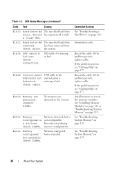
.... Reseat the cable. See "Troubleshooting System Memory" on page 160. has been removed from Check drive. E2012 Memory Memory configured, configured but is not configurable. Error detected during memory configuration. See "Troubleshooting System Memory" on page 155. Table 1-2. Review has experienced a fault. & clear SEL. Check cable. Check DIMMs. Memory detected, but...
.... Reseat the cable. See "Troubleshooting System Memory" on page 160. has been removed from Check drive. E2012 Memory Memory configured, configured but is not configurable. Error detected during memory configuration. See "Troubleshooting System Memory" on page 155. Table 1-2. Review has experienced a fault. & clear SEL. Check cable. Check DIMMs. Memory detected, but...


