Information Update
Page 4
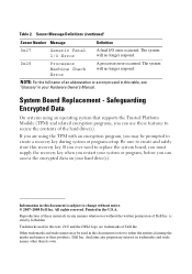
... subject to create a recovery key during system or program setup. All rights reserved. Dell Inc. System Board Replacement - NOTE: For the full name of Dell Inc. Other trademarks and trade names may be used in your hard drive(s). Safeguarding Encrypted Data On systems using an operating system that supports the Trusted Platform Module (TPM...
... subject to create a recovery key during system or program setup. All rights reserved. Dell Inc. System Board Replacement - NOTE: For the full name of Dell Inc. Other trademarks and trade names may be used in your hard drive(s). Safeguarding Encrypted Data On systems using an operating system that supports the Trusted Platform Module (TPM...
Getting Started Guide
Page 5
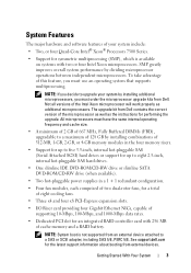
...supported from an external device attached to a SAS or SCSI adapter, including SAS 5/E, PERC 5/E. Getting Started With Your System 3 See support.dell.com for an integrated RAID controller card with two or four Intel Xeon microprocessors. NOTE: System boot is available on systems with 256 MB ... hot-pluggable power supplies in the four memory risers. • Support for up to five 3.5-inch, internal hot-pluggable SAS (Serial Attached SCSI) hard drives or support for up to upgrade your system include: • Two, or four Quad-Core Intel® Xeon® Processors 7300 Series. •...
...supported from an external device attached to a SAS or SCSI adapter, including SAS 5/E, PERC 5/E. Getting Started With Your System 3 See support.dell.com for an integrated RAID controller card with two or four Intel Xeon microprocessors. NOTE: System boot is available on systems with 256 MB ... hot-pluggable power supplies in the four memory risers. • Support for up to five 3.5-inch, internal hot-pluggable SAS (Serial Attached SCSI) hard drives or support for up to upgrade your system include: • Two, or four Quad-Core Intel® Xeon® Processors 7300 Series. •...
Getting Started Guide
Page 13
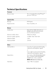
... MHz fully-buffered DIMMs with ECC protection and two-way lockstep operation Thirty-two 240-pin 512 MB, 1 GB, 2 GB, 4 GB 2 GB 128 GB Drives SAS hard drives Optical drive Flash drive Up to five 3.5-inch, internal, hot-plug, (optional) with backplane support or Up to eight 2.5-inch, internal, hot-plug, (optional) with backplane support...
... MHz fully-buffered DIMMs with ECC protection and two-way lockstep operation Thirty-two 240-pin 512 MB, 1 GB, 2 GB, 4 GB 2 GB 128 GB Drives SAS hard drives Optical drive Flash drive Up to five 3.5-inch, internal, hot-plug, (optional) with backplane support or Up to eight 2.5-inch, internal, hot-plug, (optional) with backplane support...
Hardware Owner's Manual (PDF)
Page 3
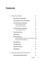
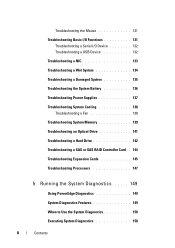
Contents 1 About Your System 11 Other Information You May Need 11 Accessing System Features During Startup 12 Front Panel Features and Indicators 13 Hard Drive Indicator Codes 15 Connecting External Devices 18 Back Panel Features and Indicators 19 Connecting External Devices 20 Power Indicator Codes 20 NIC Indications 22 LCD ...
Contents 1 About Your System 11 Other Information You May Need 11 Accessing System Features During Startup 12 Front Panel Features and Indicators 13 Hard Drive Indicator Codes 15 Connecting External Devices 18 Back Panel Features and Indicators 19 Connecting External Devices 20 Power Indicator Codes 20 NIC Indications 22 LCD ...
Hardware Owner's Manual (PDF)
Page 4
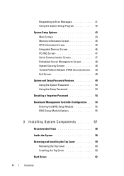
... 57 Recommended Tools 58 Inside the System 58 Removing and Installing the Top Cover 59 Removing the Top Cover 60 Installing the Top Cover 60 Hard Drives 62 4 Contents
... 57 Recommended Tools 58 Inside the System 58 Removing and Installing the Top Cover 59 Removing the Top Cover 60 Installing the Top Cover 60 Hard Drives 62 4 Contents
Hardware Owner's Manual (PDF)
Page 5
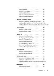
Before You Begin 62 Removing a Drive Blank 62 Installing a Drive Blank 63 Removing a Hot-Plug Hard Drive 64 Installing a Hot-Plug Hard Drive 65 Replacing a Hard Drive Carrier 66 Removing a Hard Drive From a Hard Drive Carrier 66 Installing a SAS Hard Drive Into a SATAu Drive Carrier 66 Installing a SATA Hard Drive Into a SATAu Hard Drive Carrier 67 Power Supplies 68 Removing a Power Supply 68 Installing a Power Supply 69 System Fans 70...
Before You Begin 62 Removing a Drive Blank 62 Installing a Drive Blank 63 Removing a Hot-Plug Hard Drive 64 Installing a Hot-Plug Hard Drive 65 Replacing a Hard Drive Carrier 66 Removing a Hard Drive From a Hard Drive Carrier 66 Installing a SAS Hard Drive Into a SATAu Drive Carrier 66 Installing a SATA Hard Drive Into a SATAu Hard Drive Carrier 67 Power Supplies 68 Removing a Power Supply 68 Installing a Power Supply 69 System Fans 70...
Hardware Owner's Manual (PDF)
Page 7
... Installing the I/O Riser 111 Installing a DRAC 112 SAS Backplane (Service-only Procedure 114 Removing the SAS Backplane (3.5" Hard Drives) . 114 Installing the SAS Backplane (3.5-inch Hard Drives) 116 Removing the SAS Backplane (2.5-inch Hard Drives) 116 Installing the SAS Backplane (2.5" Hard Drives) . . 119 Power Interposer Board (Service-only Procedure) . . 119 Removing the Power Interposer Board 119 Installing the...
... Installing the I/O Riser 111 Installing a DRAC 112 SAS Backplane (Service-only Procedure 114 Removing the SAS Backplane (3.5" Hard Drives) . 114 Installing the SAS Backplane (3.5-inch Hard Drives) 116 Removing the SAS Backplane (2.5-inch Hard Drives) 116 Installing the SAS Backplane (2.5" Hard Drives) . . 119 Power Interposer Board (Service-only Procedure) . . 119 Removing the Power Interposer Board 119 Installing the...
Hardware Owner's Manual (PDF)
Page 8
... System Cooling 138 Troubleshooting a Fan 138 Troubleshooting System Memory 139 Troubleshooting an Optical Drive 141 Troubleshooting a Hard Drive 142 Troubleshooting a SAS or SAS RAID Controller Card . 144 Troubleshooting Expansion Cards 145 Troubleshooting Processors 147 5 Running the System Diagnostics 149 Using PowerEdge Diagnostics 149 System Diagnostics Features 149 When to Use the System Diagnostics 150...
... System Cooling 138 Troubleshooting a Fan 138 Troubleshooting System Memory 139 Troubleshooting an Optical Drive 141 Troubleshooting a Hard Drive 142 Troubleshooting a SAS or SAS RAID Controller Card . 144 Troubleshooting Expansion Cards 145 Troubleshooting Processors 147 5 Running the System Diagnostics 149 Using PowerEdge Diagnostics 149 System Diagnostics Features 149 When to Use the System Diagnostics 150...
Hardware Owner's Manual (PDF)
Page 15
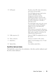
...Provides system ID, status information, and system error messages. One slimline optical drive. If the system is connected to the system. Connects a monitor to identify a particular system. Hard Drive Indicator Codes The hard drive carriers have two indicators-the drive-activity indicator and the drive-status indicator. Eight 2.5-inch hot-plug or five 3.5-inch hot-plug. ...and the LCD panel displays an error code followed by descriptive text. The LCD lights during normal system operation. 4 LCD panel. 5 USB connectors (2). 6 Video connector. 7 Hard drives. 8 Optical drive.
...Provides system ID, status information, and system error messages. One slimline optical drive. If the system is connected to the system. Connects a monitor to identify a particular system. Hard Drive Indicator Codes The hard drive carriers have two indicators-the drive-activity indicator and the drive-status indicator. Eight 2.5-inch hot-plug or five 3.5-inch hot-plug. ...and the LCD panel displays an error code followed by descriptive text. The LCD lights during normal system operation. 4 LCD panel. 5 USB connectors (2). 6 Video connector. 7 Hard drives. 8 Optical drive.

Hardware Owner's Manual (PDF)
Page 16
Hard Drive Indicators 2 1 1 green and amber drive-status indicator 2 green drive-activity indicator The Activity LED indicates command activity between the hard disk drives and storage controller. The Status LED is a bi-color (Green/Amber) LED that indicates the state of the drive as shown in a slot. The color and blink rate of the LED indicates the state of a drive in Table 1-2. 16 About Your System Figure 1-2.
Hard Drive Indicators 2 1 1 green and amber drive-status indicator 2 green drive-activity indicator The Activity LED indicates command activity between the hard disk drives and storage controller. The Status LED is a bi-color (Green/Amber) LED that indicates the state of the drive as shown in a slot. The color and blink rate of the LED indicates the state of a drive in Table 1-2. 16 About Your System Figure 1-2.

Hardware Owner's Manual (PDF)
Page 17
... the state has not been updated by the drive. Table 1-2. Hard Drive Indicators Pattern Slot empty Green element Off Drive online On Drive identify On ~250mS (prep for removal was requested). The slot is either a drive identify or a preparing for removal) Off ~250mS Drive rebuilding On ~400mS Off ~100mS Drive failed Off Predicted Failure (SMART) On ~500mS Off...
... the state has not been updated by the drive. Table 1-2. Hard Drive Indicators Pattern Slot empty Green element Off Drive online On Drive identify On ~250mS (prep for removal was requested). The slot is either a drive identify or a preparing for removal) Off ~250mS Drive rebuilding On ~400mS Off ~100mS Drive failed Off Predicted Failure (SMART) On ~500mS Off...

Hardware Owner's Manual (PDF)
Page 18
... indicator lights to Remove operation), or had a rebuild operation on any reason other than a drive failure. After the drive is off . The drive-status indicator is selected for removal, the "drive being prepared for RAID hard drives. Table 1-2. Hard Drive Indicators Pattern Rebuild Abort Green element On ~3000mS Off ~9000mS Amber eLement Off ~6000mS On ~3000mS Off ~3000mS...
... indicator lights to Remove operation), or had a rebuild operation on any reason other than a drive failure. After the drive is off . The drive-status indicator is selected for removal, the "drive being prepared for RAID hard drives. Table 1-2. Hard Drive Indicators Pattern Rebuild Abort Green element On ~3000mS Off ~9000mS Amber eLement Off ~6000mS On ~3000mS Off ~3000mS...
Hardware Owner's Manual (PDF)
Page 28
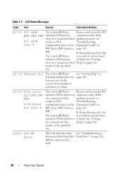
... "Troubleshooting a determined that problem persists, see "Troubleshooting Expansion Cards" on page 142. ## has experienced a fault. 28 About Your System If the error on a component that hard drive Hard Drive" on page 145. LCD Status Messages Code Test Causes Corrective Actions E1712 PCI SERR The system BIOS has Remove and reseat the PCI B## D## F## reported a PCI...
... "Troubleshooting a determined that problem persists, see "Troubleshooting Expansion Cards" on page 142. ## has experienced a fault. 28 About Your System If the error on a component that hard drive Hard Drive" on page 145. LCD Status Messages Code Test Causes Corrective Actions E1712 PCI SERR The system BIOS has Remove and reseat the PCI B## D## F## reported a PCI...

Hardware Owner's Manual (PDF)
Page 29
...& Firmware Mismatch The BMC firmware does not support the processor. E1812 HDD ## Removed The specified hard drive Information only. Reseat the cable. Error detected during memory configuration. See "Troubleshooting a Hard Drive" on memory. LCD Status Messages Code Test Causes Corrective Actions E1811 HDD ## Rbld Abrt The ...specified hard drive has experienced a rebuild abort. E2012 Unusable Memory Memory is missing or bad. E2010 No Memory No memory is ...
...& Firmware Mismatch The BMC firmware does not support the processor. E1812 HDD ## Removed The specified hard drive Information only. Reseat the cable. Error detected during memory configuration. See "Troubleshooting a Hard Drive" on memory. LCD Status Messages Code Test Causes Corrective Actions E1811 HDD ## Rbld Abrt The ...specified hard drive has experienced a rebuild abort. E2012 Unusable Memory Memory is missing or bad. E2010 No Memory No memory is ...

Hardware Owner's Manual (PDF)
Page 39
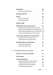
...About Your System 39 Warning Messages A warning message alerts you to a possible problem and prompts you to respond before you format a hard drive, a message will warn you that you run system diagnostics, an error message may lose all data on page 165, and then follow... include information, status, warning, and failure messages for your system. NOTE: Warning messages are not covered in "Getting Help" on the hard drive. System Messages System Message Corrective Action NOTE: For the full name of the Diagnostics Checklist in this table, see the documentation that section for...
...About Your System 39 Warning Messages A warning message alerts you to a possible problem and prompts you to respond before you format a hard drive, a message will warn you that you run system diagnostics, an error message may lose all data on page 165, and then follow... include information, status, warning, and failure messages for your system. NOTE: Warning messages are not covered in "Getting Help" on the hard drive. System Messages System Message Corrective Action NOTE: For the full name of the Diagnostics Checklist in this table, see the documentation that section for...
Hardware Owner's Manual (PDF)
Page 57
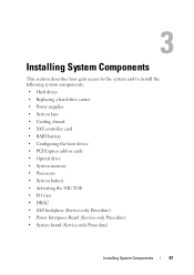
... System Components This section describes how gain access to the system and to install the following system components: • Hard drives • Replacing a hard drive carrier • Power supplies • System fans • Cooling shroud • SAS controller card • RAID... battery • Configuring the boot device • PCI Express add-in cards • Optical drive • System memory • Processors • System battery • ...
... System Components This section describes how gain access to the system and to install the following system components: • Hard drives • Replacing a hard drive carrier • Power supplies • System fans • Cooling shroud • SAS controller card • RAID... battery • Configuring the boot device • PCI Express add-in cards • Optical drive • System memory • Processors • System battery • ...

Hardware Owner's Manual (PDF)
Page 59
A crush hazard exists if the rack tilts forward. Installing System Components 59 Figure 3-1. This could cause serious injury and/or death. Inside the System 8 7 9 6 5 4 3 2 1 10 1 Front fan 3 RAID controller 5 Processor heat sink 7 Memory riser 9 PCI Express card 2 Intrusion switch 4 SAS backplane 6 Center brace 8 Back fan 10 Hard drives Removing and Installing the Top Cover CAUTION: If the system is rack mounted, make sure the rack is anchored securely so it will not tilt forward when the server is extended.
A crush hazard exists if the rack tilts forward. Installing System Components 59 Figure 3-1. This could cause serious injury and/or death. Inside the System 8 7 9 6 5 4 3 2 1 10 1 Front fan 3 RAID controller 5 Processor heat sink 7 Memory riser 9 PCI Express card 2 Intrusion switch 4 SAS backplane 6 Center brace 8 Back fan 10 Hard drives Removing and Installing the Top Cover CAUTION: If the system is rack mounted, make sure the rack is anchored securely so it will not tilt forward when the server is extended.
Hardware Owner's Manual (PDF)
Page 62
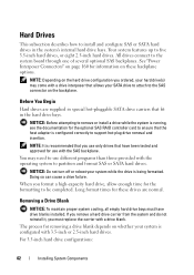
... completed. For 3.5-inch hard drive configurations: 62 Installing System Components All drives connect to five 3.5-inch hard drives, or eight 2.5-inch hard drives. NOTICE: Do not turn off or reboot your SATA drive to attach to the SAS connector on these drives are supplied in special hot-pluggable SATA drive carriers that fit in the system's internal hard drive bays. You may...
... completed. For 3.5-inch hard drive configurations: 62 Installing System Components All drives connect to five 3.5-inch hard drives, or eight 2.5-inch hard drives. NOTICE: Do not turn off or reboot your SATA drive to attach to the SAS connector on these drives are supplied in special hot-pluggable SATA drive carriers that fit in the system's internal hard drive bays. You may...
Hardware Owner's Manual (PDF)
Page 63
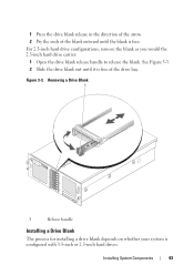
... out until the blank is free. For 2.5-inch hard drive configurations, remove the blank as you would the 2.5-inch hard drive carrier: 1 Open the drive blank release handle to release the blank. Removing a Drive Blank 1 1 Release handle Installing a Drive Blank The process for installing a drive blank depends on whether your system is free of the blank outward until...
... out until the blank is free. For 2.5-inch hard drive configurations, remove the blank as you would the 2.5-inch hard drive carrier: 1 Open the drive blank release handle to release the blank. Removing a Drive Blank 1 1 Release handle Installing a Drive Blank The process for installing a drive blank depends on whether your system is free of the blank outward until...
Hardware Owner's Manual (PDF)
Page 64
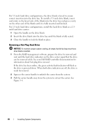
...blank until the hard drive indicators on the drive carrier signal that the drive can be removed safely. When both drive indicators are off, the drive is ready for information about hot-plug drive removal. For 2.5-inch hard drive configurations, install the hard drive blank as the drive is powered down... from the system to extract the carrier. Removing a Hot-Plug Hard Drive NOTICE: To maintain proper system cooling, all empty hard drive bays must have drive blanks installed. 1 From the RAID management software, prepare the drive for removal and wait until it is fully inserted and latched....
...blank until the hard drive indicators on the drive carrier signal that the drive can be removed safely. When both drive indicators are off, the drive is ready for information about hot-plug drive removal. For 2.5-inch hard drive configurations, install the hard drive blank as the drive is powered down... from the system to extract the carrier. Removing a Hot-Plug Hard Drive NOTICE: To maintain proper system cooling, all empty hard drive bays must have drive blanks installed. 1 From the RAID management software, prepare the drive for removal and wait until it is fully inserted and latched....


