Information Update
Page 1
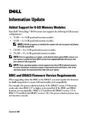
... fully supported. BMC and DRAC5 Firmware Version Requirements When upgrading either the BMC or the DRAC5, you must update the firmware for 8-GB Memory Modules Your Dell™ PowerEdge™ R900 system now supports the following 8-GB memory configurations: • 32 GB - 4 x 8-GB quad-rank memory modules • 64 GB - 8 x 8-GB quad-rank memory modules NOTE: If 64 GB of memory is installed, the system will ensure that ships with DRAC5 version 1.40-the power...
... fully supported. BMC and DRAC5 Firmware Version Requirements When upgrading either the BMC or the DRAC5, you must update the firmware for 8-GB Memory Modules Your Dell™ PowerEdge™ R900 system now supports the following 8-GB memory configurations: • 32 GB - 4 x 8-GB quad-rank memory modules • 64 GB - 8 x 8-GB quad-rank memory modules NOTE: If 64 GB of memory is installed, the system will ensure that ships with DRAC5 version 1.40-the power...
Hardware Owner's Manual (PDF)
Page 13
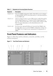
... drives on setup and use of DRAC. Front Panel Features and Indicators 1 23 45 6 7 8 About Your System 13 This keystroke allows you have the optional Dell Remote Assistant Card (DRAC), this keystroke allows access to configure an optional RAID card. Figure 1-1. Table 1-1. See the DRAC User's Guide for more information, see the documentation for Accessing System Functions Keystroke Description Enters the RAID configuration utility, which allows you have PXE support enabled...
... drives on setup and use of DRAC. Front Panel Features and Indicators 1 23 45 6 7 8 About Your System 13 This keystroke allows you have the optional Dell Remote Assistant Card (DRAC), this keystroke allows access to configure an optional RAID card. Figure 1-1. Table 1-1. See the DRAC User's Guide for more information, see the documentation for Accessing System Functions Keystroke Description Enters the RAID configuration utility, which allows you have PXE support enabled...
Hardware Owner's Manual (PDF)
Page 27
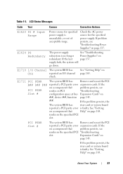
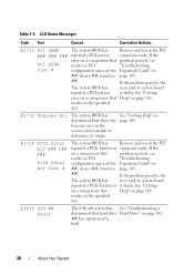
... Status Messages Code Test Causes Corrective Actions E1620 PS # Input Range Power source for the specified power supply. If problem persists, see resides in the specified PCI "Troubleshooting slot. If the on a component that Help" on ##, device ##, function page 145. ##. PCI PERR Slot # The system BIOS has Remove and reseat the PCI reported a PCI parity error expansion cards. E1624 PS Redundancy The power supply See "Troubleshooting subsystem is faulty. resides in PCI "Troubleshooting Slot # configuration space at bus Expansion Cards" on...
... Status Messages Code Test Causes Corrective Actions E1620 PS # Input Range Power source for the specified power supply. If problem persists, see resides in the specified PCI "Troubleshooting slot. If the on a component that Help" on ##, device ##, function page 145. ##. PCI PERR Slot # The system BIOS has Remove and reseat the PCI reported a PCI parity error expansion cards. E1624 PS Redundancy The power supply See "Troubleshooting subsystem is faulty. resides in PCI "Troubleshooting Slot # configuration space at bus Expansion Cards" on...
Hardware Owner's Manual (PDF)
Page 28
... Unknown Err The system BIOS has determined that problem persists, see "Troubleshooting Expansion Cards" on a component that there has been an error in PCI "Troubleshooting Slot # configuration space at bus ##, device ##, function ##. LCD Status Messages Code Test Causes Corrective Actions E1712 PCI SERR The system BIOS has Remove and reseat the PCI B## D## F## reported a PCI system expansion cards. The system BIOS has reported a PCIe fatal error on a component that resides in PCI configuration space at bus Expansion Cards" on a component that resides...
... Unknown Err The system BIOS has determined that problem persists, see "Troubleshooting Expansion Cards" on a component that there has been an error in PCI "Troubleshooting Slot # configuration space at bus ##, device ##, function ##. LCD Status Messages Code Test Causes Corrective Actions E1712 PCI SERR The system BIOS has Remove and reseat the PCI B## D## F## reported a PCI system expansion cards. The system BIOS has reported a PCIe fatal error on a component that resides in PCI configuration space at bus Expansion Cards" on a component that resides...

Hardware Owner's Manual (PDF)
Page 29
... See the BMC User's Guide for more information on page 78. E2010 No Memory No memory is not configurable. E2012 Unusable Memory Memory is configured, but is installed in the system. See "SAS Controller Card" on setup and use of BMC. See "Troubleshooting System Memory" on page 142. E1812 HDD ## Removed The specified hard drive Information only. If problem persists, replace cable. page 139. See "Troubleshooting a Hard Drive" on page 139. Memory System Memory" on page 92. LCD Status Messages Code Test Causes...
... See the BMC User's Guide for more information on page 78. E2010 No Memory No memory is not configurable. E2012 Unusable Memory Memory is configured, but is installed in the system. See "SAS Controller Card" on setup and use of BMC. See "Troubleshooting System Memory" on page 142. E1812 HDD ## Removed The specified hard drive Information only. If problem persists, replace cable. page 139. See "Troubleshooting a Hard Drive" on page 139. Memory System Memory" on page 92. LCD Status Messages Code Test Causes...

Hardware Owner's Manual (PDF)
Page 31
... the BIOS. Check screen for specific configuration. If no memory riser card is present, the "Crd #" string is rebooted. Table 1-5. If problem persists, see your DRAC documentation. will not resume logging further SBEs until the system is left out of the message. E2020 CPU Config processor configuration failure. E2022 POST Fail General failure after video. Ensure that DRAC cables and connectors are properly seated. "Troubleshooting System Memory" on error (SBE) logging, and page 139. LCD Status Messages Code Test Causes...
... the BIOS. Check screen for specific configuration. If no memory riser card is present, the "Crd #" string is rebooted. Table 1-5. If problem persists, see your DRAC documentation. will not resume logging further SBEs until the system is left out of the message. E2020 CPU Config processor configuration failure. E2022 POST Fail General failure after video. Ensure that DRAC cables and connectors are properly seated. "Troubleshooting System Memory" on error (SBE) logging, and page 139. LCD Status Messages Code Test Causes...

Hardware Owner's Manual (PDF)
Page 35
... Setup program, loose diskette/tape drive interface cable, or loose power cable Replace the diskette. Redundant memory was set to the recommended memory configuration or press any memory configuration error, but the current configuration does not support redundant memory. detected and is installed. This warning message will be removed. Change it to enabled in CMOS, but the memory configuration is not validated. NVRAM_CLR jumper should be displayed when there is no any key to update Remote Remote Configuration request has been Configuration. Table 1-6. System Messages...
... Setup program, loose diskette/tape drive interface cable, or loose power cable Replace the diskette. Redundant memory was set to the recommended memory configuration or press any memory configuration error, but the current configuration does not support redundant memory. detected and is installed. This warning message will be removed. Change it to enabled in CMOS, but the memory configuration is not validated. NVRAM_CLR jumper should be displayed when there is no any key to update Remote Remote Configuration request has been Configuration. Table 1-6. System Messages...

Hardware Owner's Manual (PDF)
Page 37
... on hard-disk drive Incorrect configuration settings in System Setup program, or no operating system on hard-disk drive No timer tick interrupt Defective system board Not a boot diskette No operating system on diskette PCI BIOS failed to installed PCI device BIOS (Option ROM) checksum failure is detected during shadowing Plug & Play Configuration error Plug & Play Configuration error is detected during PCI device scan Read fault Requested sector not found Faulty diskette, diskette/tape drive subsystem, or hard-disk drive subsystem Remote Configuration update System was unable to...
... on hard-disk drive Incorrect configuration settings in System Setup program, or no operating system on hard-disk drive No timer tick interrupt Defective system board Not a boot diskette No operating system on diskette PCI BIOS failed to installed PCI device BIOS (Option ROM) checksum failure is detected during shadowing Plug & Play Configuration error Plug & Play Configuration error is detected during PCI device scan Read fault Requested sector not found Faulty diskette, diskette/tape drive subsystem, or hard-disk drive subsystem Remote Configuration update System was unable to...

Hardware Owner's Manual (PDF)
Page 38
... detected in DIMM installed in protected mode Improperly seated DIMMs or faulty keyboard/mouse controller chip Unsupported CPU combination The installed processors cannot be installed at the same time. not supported. Utility partition not available Utility partition is the RAID DIMM slot! System Messages System Message Corrective Action ROM bad checksum = address Expansion card improperly installed or faulty Sector not found Defective sectors on diskette or hard-disk drive Seek error Defective sectors on selected drive BIOS Update Attempt Failed BIOS remote update...
... detected in DIMM installed in protected mode Improperly seated DIMMs or faulty keyboard/mouse controller chip Unsupported CPU combination The installed processors cannot be installed at the same time. not supported. Utility partition not available Utility partition is the RAID DIMM slot! System Messages System Message Corrective Action ROM bad checksum = address Expansion card improperly installed or faulty Sector not found Defective sectors on diskette or hard-disk drive Seek error Defective sectors on selected drive BIOS Update Attempt Failed BIOS remote update...

Hardware Owner's Manual (PDF)
Page 49
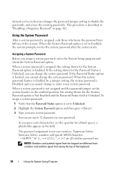
... data encryption programs. NOTICE: Anyone can disable the password by changing a jumper setting. To change settings in the System Setup program until a Using the System Setup Program 49 Your system is a concern, operate your system or change an existing password, you leave your system. Trusted Platform Module (TPM) Security Screen Table 2-10 lists the options and descriptions for the data on page 52). If your data requires more security, use...
... data encryption programs. NOTICE: Anyone can disable the password by changing a jumper setting. To change settings in the System Setup program until a Using the System Setup Program 49 Your system is a concern, operate your system or change an existing password, you leave your system. Trusted Platform Module (TPM) Security Screen Table 2-10 lists the options and descriptions for the data on page 52). If your data requires more security, use...
Hardware Owner's Manual (PDF)
Page 50
... System Setup program and check the System Password option. Assigning a System Password Before you for the System Password option is in "Disabling a Forgotten Password" on page 162. To assign a system password: 1 Verify that the Password Status option is set to Unlocked. 2 Highlight the System Password option and then press . 3 Type your password. When a system password is not assigned and the password jumper on the system board is Enabled. NOTE: Numbers...
... System Setup program and check the System Password option. Assigning a System Password Before you for the System Password option is in "Disabling a Forgotten Password" on page 162. To assign a system password: 1 Verify that the Password Status option is set to Unlocked. 2 Highlight the System Password option and then press . 3 Type your password. When a system password is not assigned and the password jumper on the system board is Enabled. NOTE: Numbers...
Hardware Owner's Manual (PDF)
Page 54
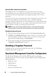
.... 2 Highlight the Setup Password option, press to access the setup password window, and press twice to enter a password. Baseboard Management Controller Configuration The Baseboard Management Controller (BMC) enables configuring, monitoring, and recovery of the System Setup options. Operating With a Setup Password Enabled If Setup Password is not locked through the Password Status option, you can modify most of systems remotely. NOTE: You can use the Password Status option in "Assigning a Setup Password" on page 53. The setting changes to Not Enabled. 3 If you view, but not...
.... 2 Highlight the Setup Password option, press to access the setup password window, and press twice to enter a password. Baseboard Management Controller Configuration The Baseboard Management Controller (BMC) enables configuring, monitoring, and recovery of the System Setup options. Operating With a Setup Password Enabled If Setup Password is not locked through the Password Status option, you can modify most of systems remotely. NOTE: You can use the Password Status option in "Assigning a Setup Password" on page 53. The setting changes to Not Enabled. 3 If you view, but not...
Hardware Owner's Manual (PDF)
Page 57
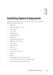
... system components: • Hard drives • Replacing a hard drive carrier • Power supplies • System fans • Cooling shroud • SAS controller card • RAID battery • Configuring the boot device • PCI Express add-in cards • Optical drive • System memory • Processors • System battery • Activating the NIC TOE • I/O riser • DRAC • SAS backplane (Service-only Procedure) • Power Interposer Board (Service-only Procedure) • System board (Service-only Procedure) Installing System Components 57
... system components: • Hard drives • Replacing a hard drive carrier • Power supplies • System fans • Cooling shroud • SAS controller card • RAID battery • Configuring the boot device • PCI Express add-in cards • Optical drive • System memory • Processors • System battery • Activating the NIC TOE • I/O riser • DRAC • SAS backplane (Service-only Procedure) • Power Interposer Board (Service-only Procedure) • System board (Service-only Procedure) Installing System Components 57
Hardware Owner's Manual (PDF)
Page 86
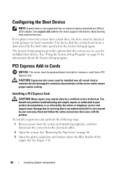
... service technician. PCI Express Add-in Cards NOTICE: The server must be installed over all vacant slots to maintain the electromagnetic emission characteristics of the empty slot. See support.dell.com for information about booting from external devices. See "Using the System Setup Program" on page 60. 3 Open the plastic expansion-card retainer above the filler bracket of the server and to scan for installed boot devices. Damage due to a SAS or SCSI adapter. Configuring...
... service technician. PCI Express Add-in Cards NOTICE: The server must be installed over all vacant slots to maintain the electromagnetic emission characteristics of the empty slot. See support.dell.com for information about booting from external devices. See "Using the System Setup Program" on page 60. 3 Open the plastic expansion-card retainer above the filler bracket of the server and to scan for installed boot devices. Damage due to a SAS or SCSI adapter. Configuring...

Hardware Owner's Manual (PDF)
Page 99
... the bottom edge of the memory board. 5 Pull the cover away from the memory riser. 6 Lift the memory riser DIMM cover from its antistatic container. Removing the Memory Riser Cover 1 Ensure power is required, FBDIMMs installed in the lowest numbered available slots. See "Removing the Top Cover" on page 98. 3 Position the DIMM above the socket. See "Removing a Memory Riser" on page 96. 4 Press down on the memory board cover hooks, straddling the memory board slot connector on...
... the bottom edge of the memory board. 5 Pull the cover away from the memory riser. 6 Lift the memory riser DIMM cover from its antistatic container. Removing the Memory Riser Cover 1 Ensure power is required, FBDIMMs installed in the lowest numbered available slots. See "Removing the Top Cover" on page 98. 3 Position the DIMM above the socket. See "Removing a Memory Riser" on page 96. 4 Press down on the memory board cover hooks, straddling the memory board slot connector on...
Hardware Owner's Manual (PDF)
Page 132
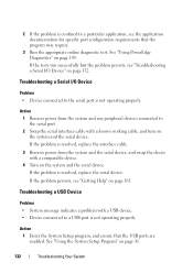
... documentation for specific port configuration requirements that the USB ports are enabled. Action 1 Enter the System Setup program, and ensure that the program may require. 3 Run the appropriate online diagnostic test. If the problem is resolved, replace the interface cable. 3 Remove power from the system and any peripheral devices connected to the serial port is not operating properly. Troubleshooting a USB Device Problem • System message indicates a problem with a comparable device. 4 Turn on page 41. 132 Troubleshooting Your System See "Using the System Setup...
... documentation for specific port configuration requirements that the USB ports are enabled. Action 1 Enter the System Setup program, and ensure that the program may require. 3 Run the appropriate online diagnostic test. If the problem is resolved, replace the interface cable. 3 Remove power from the system and any peripheral devices connected to the serial port is not operating properly. Troubleshooting a USB Device Problem • System message indicates a problem with a comparable device. 4 Turn on page 41. 132 Troubleshooting Your System See "Using the System Setup...
Hardware Owner's Manual (PDF)
Page 133
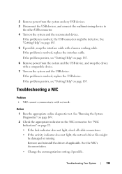
.... 5 If possible, swap the interface cable with a known working cable. Troubleshooting Your System 133 2 Remove power from the system and the USB device, and swap the device with a comparable device. 7 Turn on page 165. If the problem is resolved, replace the interface cable. If the problem is resolved, replace the USB device. See the NIC's documentation. • Change the autonegotiation setting, if possible. See "Running the System Diagnostics" on page 149. 2 Check the appropriate indicator on...
.... 5 If possible, swap the interface cable with a known working cable. Troubleshooting Your System 133 2 Remove power from the system and the USB device, and swap the device with a comparable device. 7 Turn on page 165. If the problem is resolved, replace the interface cable. If the problem is resolved, replace the USB device. See the NIC's documentation. • Change the autonegotiation setting, if possible. See "Running the System Diagnostics" on page 149. 2 Check the appropriate indicator on...
Hardware Owner's Manual (PDF)
Page 134
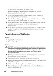
... data transmission speed. See "Removing the Top Cover" on the system. • Excessive humidity. See "PCI Express Addin Cards" on the network are all expansion cards installed in Cards" on the switch or hub. See the network equipment documentation. 6 Ensure that all expansion cards installed in your Product Information Guide for at least 24 hours. 5 Reinstall all network cables are of an integrated NIC, see your Getting Started Guide. Action CAUTION: Only trained service...
... data transmission speed. See "Removing the Top Cover" on the system. • Excessive humidity. See "PCI Express Addin Cards" on the network are all expansion cards installed in Cards" on the switch or hub. See the network equipment documentation. 6 Ensure that all expansion cards installed in your Product Information Guide for at least 24 hours. 5 Reinstall all network cables are of an integrated NIC, see your Getting Started Guide. Action CAUTION: Only trained service...
Hardware Owner's Manual (PDF)
Page 141
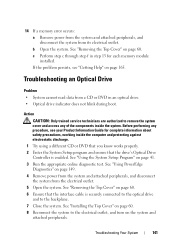
... a memory error occurs: a Remove power from the system and attached peripherals, and disconnect the system from the electrical outlet. 5 Open the system. Troubleshooting an Optical Drive Problem • System cannot read data from a CD or DVD in step 13 for complete information about safety precautions, working inside the system. See "Using PowerEdge Diagnostics" on page 60. 6 Ensure that the drive's Optical Drive Controller is securely connected to...
... a memory error occurs: a Remove power from the system and attached peripherals, and disconnect the system from the electrical outlet. 5 Open the system. Troubleshooting an Optical Drive Problem • System cannot read data from a CD or DVD in step 13 for complete information about safety precautions, working inside the system. See "Using PowerEdge Diagnostics" on page 60. 6 Ensure that the drive's Optical Drive Controller is securely connected to...
Hardware Owner's Manual (PDF)
Page 143
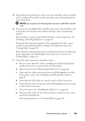
... have a SAS RAID controller card. 6 If you have intermittent problems. Replace the hard drive carrier. See "Removing the Top Cover" on page 165. 7 Check the cable connections inside the system: a Remove power from the system, including any attached peripherals, and disconnect the system from the electrical outlet. g Reconnect the system to the electrical outlet, and turn on page 165. b Open the system. d Verify that the required device drivers for more...
... have a SAS RAID controller card. 6 If you have intermittent problems. Replace the hard drive carrier. See "Removing the Top Cover" on page 165. 7 Check the cable connections inside the system: a Remove power from the system, including any attached peripherals, and disconnect the system from the electrical outlet. g Reconnect the system to the electrical outlet, and turn on page 165. b Open the system. d Verify that the required device drivers for more...


