

Hardware Owner's Manual (PDF)
Page 5
... Removing the Diskette Drive 72 Installing the Diskette Drive Into the Drive Carrier 74 Installing the Diskette Drive 74 System Battery 75 Replacing the System Battery 75 Cooling Shroud 77 Removing the Cooling Shroud 77 Installing the Cooling Shroud 79 Fan Brackets 79 Removing the Center Fan Bracket 79 Replacing the Center Fan Bracket 79 Removing...
... Removing the Diskette Drive 72 Installing the Diskette Drive Into the Drive Carrier 74 Installing the Diskette Drive 74 System Battery 75 Replacing the System Battery 75 Cooling Shroud 77 Removing the Cooling Shroud 77 Installing the Cooling Shroud 79 Fan Brackets 79 Removing the Center Fan Bracket 79 Replacing the Center Fan Bracket 79 Removing...
Hardware Owner's Manual (PDF)
Page 25
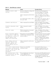
... cable, or loose power cable. See "Troubleshooting a Diskette Drive" on page 112. Replace the diskette. Mismatched or unmatched DIMMs installed; If the problem persists, see "Troubleshooting a Diskette Drive" on page 80. on page 112. Remote Access Controller initialization failure Ensure that only Dell-qualified memory is properly installed. See "Installing a RAC Card" on page...
... cable, or loose power cable. See "Troubleshooting a Diskette Drive" on page 112. Replace the diskette. Mismatched or unmatched DIMMs installed; If the problem persists, see "Troubleshooting a Diskette Drive" on page 80. on page 112. Remote Access Controller initialization failure Ensure that only Dell-qualified memory is properly installed. See "Installing a RAC Card" on page...
Hardware Owner's Manual (PDF)
Page 28
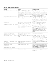
... installed problem persists, see "Troubleshooting Expansion Cards" on page 117. Install the NVRAM_CLR jumper and reboot the system. Replace the diskette. ROM bad checksum = address Expansion card improperly installed or Reseat the expansion cards. page 115. Loose ... securely shadowing. Retry Remote Configuration. Plug & Play Configuration Error Error encountered in your system. See Figure 6-1 for the appropriate drive(s) installed in your system. all appropriate cables are securely connected to the expansion cards. See "Troubleshooting System Memory" on page ...
... installed problem persists, see "Troubleshooting Expansion Cards" on page 117. Install the NVRAM_CLR jumper and reboot the system. Replace the diskette. ROM bad checksum = address Expansion card improperly installed or Reseat the expansion cards. page 115. Loose ... securely shadowing. Retry Remote Configuration. Plug & Play Configuration Error Error encountered in your system. See Figure 6-1 for the appropriate drive(s) installed in your system. all appropriate cables are securely connected to the expansion cards. See "Troubleshooting System Memory" on page ...
Hardware Owner's Manual (PDF)
Page 29
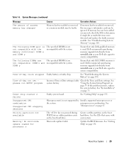
..." on the boot hard drive. faulty Check the Time and Date settings. Dell recommends purchasing memory upgrade kits directly from www.dell.com or your Dell sales agent to determine if single-bit or multi-bit errors were detected and replace the faulty memory module. ...to ensure compatibility. "Using the System Setup Program" on the boot hard drive. See "Microprocessor" on page 131. See "Getting Help" on page 87. microprocessor combination. If the problem persists, replace the system battery. About Your System 29 Table 1-5. See "Troubleshooting System ...
..." on the boot hard drive. faulty Check the Time and Date settings. Dell recommends purchasing memory upgrade kits directly from www.dell.com or your Dell sales agent to determine if single-bit or multi-bit errors were detected and replace the faulty memory module. ...to ensure compatibility. "Using the System Setup Program" on the boot hard drive. See "Microprocessor" on page 131. See "Getting Help" on page 87. microprocessor combination. If the problem persists, replace the system battery. About Your System 29 Table 1-5. See "Troubleshooting System ...
Hardware Owner's Manual (PDF)
Page 52
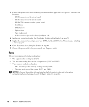
... (FAN2 and FAN3) • Three memory module cooling fans: - 3 Connect the power cables to the following components where applicable (see Figure 3-4) 4 Replace the center fan bracket. One fan on page 53. 6 Close the system. See "Removing and Installing a Fan" on top of a problem with a... on the system board • PWR CTRL connector on the system board • Hard drives • Diskette drive • Optical drive • Tape backup unit • Cable retention clips on page 79. 5 Replace the expansion-bay and processor fans (FAN1, FAN2, and FAN3). See "Closing the System...
... (FAN2 and FAN3) • Three memory module cooling fans: - 3 Connect the power cables to the following components where applicable (see Figure 3-4) 4 Replace the center fan bracket. One fan on page 53. 6 Close the system. See "Removing and Installing a Fan" on top of a problem with a... on the system board • PWR CTRL connector on the system board • Hard drives • Diskette drive • Optical drive • Tape backup unit • Cable retention clips on page 79. 5 Replace the expansion-bay and processor fans (FAN1, FAN2, and FAN3). See "Closing the System...
Hardware Owner's Manual (PDF)
Page 66
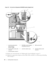
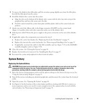
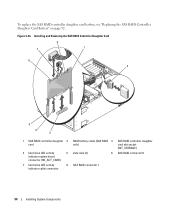
... (HD_ACT_CARD) 2 SAS RAID controller daughter 3 SASx connector (2) card battery connector 4 hard drive LED activity cable 5 center fan retention cage connector 6 hard drive interface cable connector 7 hard drive power connector 5 Replace the center fan bracket. See "Removing and Installing a Fan" on page 79. 6 Replace the expansion-bay and processor fans (FAN1, FAN2, and FAN3). Figure 3-14.
... (HD_ACT_CARD) 2 SAS RAID controller daughter 3 SASx connector (2) card battery connector 4 hard drive LED activity cable 5 center fan retention cage connector 6 hard drive interface cable connector 7 hard drive power connector 5 Replace the center fan bracket. See "Removing and Installing a Fan" on page 79. 6 Replace the expansion-bay and processor fans (FAN1, FAN2, and FAN3). Figure 3-14.
Hardware Owner's Manual (PDF)
Page 67
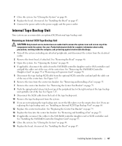
... page 46. 3 Open the system. 7 Close the system. See "Removing the Bezel" on page 48. 8 Replace the bezel, if removed. See "Removing and Installing a Fan" on page 48. 16 Replace the bezel, if removed. Installing System Components 67 See "Closing the System" on page 53. 14 If applicable, ...Card" on page 93 or "Removing an Expansion Card" on page 68. 12 Replace the center fan bracket. If you are not replacing the tape backup unit, insert the filler plate over the empty drive slot. Internal Tape Backup Unit Your system can accommodate an optional SCSI internal tape backup...
... page 46. 3 Open the system. 7 Close the system. See "Removing the Bezel" on page 48. 8 Replace the bezel, if removed. See "Removing and Installing a Fan" on page 48. 16 Replace the bezel, if removed. Installing System Components 67 See "Closing the System" on page 53. 14 If applicable, ...Card" on page 93 or "Removing an Expansion Card" on page 68. 12 Replace the center fan bracket. If you are not replacing the tape backup unit, insert the filler plate over the empty drive slot. Internal Tape Backup Unit Your system can accommodate an optional SCSI internal tape backup...
Hardware Owner's Manual (PDF)
Page 69
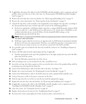
... end of the way into the bay until the spring latch engages. 17 Replace the fans into the drive slot on the peripheral bay, with the tape drive, based on page 53. 18 If applicable, reconnect the cables to the drive, install them on the SCSI bus. b Draw the filler plate upward and...device) connected to the SCSI controller. 8 If a controller card was included in the drive kit to the documentation that all devices in order by ID number. See Figure 3-15. 13 Replace the center fan bracket. See "Replacing the Center Fan Bracket" on page 79. 14 Connect the SCSI interface cable to the...
... end of the way into the bay until the spring latch engages. 17 Replace the fans into the drive slot on the peripheral bay, with the tape drive, based on page 53. 18 If applicable, reconnect the cables to the drive, install them on the SCSI bus. b Draw the filler plate upward and...device) connected to the SCSI controller. 8 If a controller card was included in the drive kit to the documentation that all devices in order by ID number. See Figure 3-15. 13 Replace the center fan bracket. See "Replacing the Center Fan Bracket" on page 79. 14 Connect the SCSI interface cable to the...
Hardware Owner's Manual (PDF)
Page 70
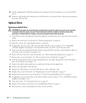
... cables out of the way of the center fans. 5 Disconnect the tape backup SCSI cable from the bay. 11 Replace the optical drive or insert the filler plate over the empty drive slot. 12 Replace the center fan bracket. See your Product Information Guide for complete information about safety precautions, working inside the computer...
... cables out of the way of the center fans. 5 Disconnect the tape backup SCSI cable from the bay. 11 Replace the optical drive or insert the filler plate over the empty drive slot. 12 Replace the center fan bracket. See your Product Information Guide for complete information about safety precautions, working inside the computer...
Hardware Owner's Manual (PDF)
Page 71
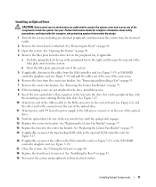
... peripherals to the CD power connect or on the rear of the optical drive. 12 Push the optical drive the rest of the way into the bay until the spring latch engages. 13 Replace the center fan bracket. See "Replacing the Center Fan Bracket" on page 53. 7 Remove the center fan ... "Removing the Bezel" on page 48. 18 Replace the front bezel, if removed. Installing an Optical Drive CAUTION: Only trained service technicians are not attached to the drive, install them now. 9 Insert the new optical drive three-quarters of the way into the drive slot on the peripheral bay, with the mounting ...
... peripherals to the CD power connect or on the rear of the optical drive. 12 Push the optical drive the rest of the way into the bay until the spring latch engages. 13 Replace the center fan bracket. See "Replacing the Center Fan Bracket" on page 53. 7 Remove the center fan ... "Removing the Bezel" on page 48. 18 Replace the front bezel, if removed. Installing an Optical Drive CAUTION: Only trained service technicians are not attached to the drive, install them now. 9 Insert the new optical drive three-quarters of the way into the drive slot on the peripheral bay, with the mounting ...
Hardware Owner's Manual (PDF)
Page 75
...Removing and Installing a Fan" on page 53 c If applicable, reconnect the cables to the power connector on the rear of the diskette drive. 9 If applicable, replace the components your Product Information Guide for the location of the system battery and then, starting with PCI slot 6, remove as many expansion cards... on page 48. 11 Replace the front bezel, if removed. b Replace the fans into position. 7 Attach one end of the ribbon cable to the floppy connector (FLOPPY) on the system board (Figure 6-2) and the other end to the connector on the rear of the diskette drive. 8 Attach power cable ...
...Removing and Installing a Fan" on page 53 c If applicable, reconnect the cables to the power connector on the rear of the diskette drive. 9 If applicable, replace the components your Product Information Guide for the location of the system battery and then, starting with PCI slot 6, remove as many expansion cards... on page 48. 11 Replace the front bezel, if removed. b Replace the fans into position. 7 Attach one end of the ribbon cable to the floppy connector (FLOPPY) on the system board (Figure 6-2) and the other end to the connector on the rear of the diskette drive. 8 Attach power cable ...
Hardware Owner's Manual (PDF)
Page 92
... 3-25. 3 Insert the new battery into the battery bay, ensuring that came with your hard drives in level 0, 1, 5, or 10 RAID configurations. See Figure 3-25. 92 Installing System Components Replacing the SAS RAID Controller Daughter Card Battery 1 Disconnect the battery cable from the expansion-bay bracket by... Pull the connector through the routing hole and connect the storage card battery cable to set up to six SAS or SATA hard drives and enables you to the SAS RAID controller daughter card. For more information, see the documentation that the battery is aligned and fully...
... 3-25. 3 Insert the new battery into the battery bay, ensuring that came with your hard drives in level 0, 1, 5, or 10 RAID configurations. See Figure 3-25. 92 Installing System Components Replacing the SAS RAID Controller Daughter Card Battery 1 Disconnect the battery cable from the expansion-bay bracket by... Pull the connector through the routing hole and connect the storage card battery cable to set up to six SAS or SATA hard drives and enables you to the SAS RAID controller daughter card. For more information, see the documentation that the battery is aligned and fully...
Hardware Owner's Manual (PDF)
Page 93
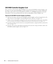
See Figure 3-26. Installing System Components 93 Figure 3-25. See Figure 3-26. 2 Remove the hard drive LED activity cable from the controller card by releasing the tab on the cable connector on the system board. Replacing a SAS RAID Controller Daughter Card Battery 8 9 1 7 2 6 5 4 3 1 connector release tab 2 routing hole for RAID battery 3 RAID battery cable...
See Figure 3-26. Installing System Components 93 Figure 3-25. See Figure 3-26. 2 Remove the hard drive LED activity cable from the controller card by releasing the tab on the cable connector on the system board. Replacing a SAS RAID Controller Daughter Card Battery 8 9 1 7 2 6 5 4 3 1 connector release tab 2 routing hole for RAID battery 3 RAID battery cable...
Hardware Owner's Manual (PDF)
Page 94
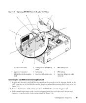
...Daughter Card 8 7 1 6 2 5 4 3 1 SAS RAID controller daughter 2 card 4 hard drive LED activity 5 indicator system board connector (HD_ACT_CARD) 7 hard drive LED activity 8 indicator cable connector RAID battery cable (SAS RAID 3 only) slide rails (2) 6 ...SAS RAID connector 1 SAS RAID controller daughter card slot socket (INT_STORAGE) SAS RAID connector 0 94 Installing System Components Figure 3-26. To replace the SAS RAID controller daughter card battery, see "Replacing...
...Daughter Card 8 7 1 6 2 5 4 3 1 SAS RAID controller daughter 2 card 4 hard drive LED activity 5 indicator system board connector (HD_ACT_CARD) 7 hard drive LED activity 8 indicator cable connector RAID battery cable (SAS RAID 3 only) slide rails (2) 6 ...SAS RAID connector 1 SAS RAID controller daughter card slot socket (INT_STORAGE) SAS RAID connector 0 94 Installing System Components Figure 3-26. To replace the SAS RAID controller daughter card battery, see "Replacing...
Hardware Owner's Manual (PDF)
Page 95
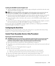
...seats into the slide rails and slide the card down until it clears the chassis hooks and lift up to replace the SAS RAID controller daughter card battery, see "Replacing the SAS RAID Controller Daughter Card Battery" on page 33. See Figure 3-27. 6 Remove the three ...Setup program. Installing System Components 95 See your Product Information Guide for complete information about safety precautions, working inside the system. Configuring the Boot Drive By default, the system boots from the electrical outlet and peripherals. 3 Open the system. See Figure 3-27. See Figure 3-26 and ...
...seats into the slide rails and slide the card down until it clears the chassis hooks and lift up to replace the SAS RAID controller daughter card battery, see "Replacing the SAS RAID Controller Daughter Card Battery" on page 33. See Figure 3-27. 6 Remove the three ...Setup program. Installing System Components 95 See your Product Information Guide for complete information about safety precautions, working inside the system. Configuring the Boot Drive By default, the system boots from the electrical outlet and peripherals. 3 Open the system. See Figure 3-27. See Figure 3-26 and ...
Hardware Owner's Manual (PDF)
Page 114
... System" on page 48. 10 Ensure that the SCSI controller card is terminated or not terminated, based on the interface cable used to connect the drive. See "Removing the Bezel" on page 121. 7 Open or remove the bezel. See "Closing the System" on page 48. 12 Reconnect the system...page 57. 11 Close the system. • Missing or corrupted tape-backup software or tape drive device driver • Defective SCSI controller Action 1 Remove the tape cartridge you were using when the problem occurred, and replace it with a tape cartridge that you cannot resolve the problem, see "Getting Help" on page...
... System" on page 48. 10 Ensure that the SCSI controller card is terminated or not terminated, based on the interface cable used to connect the drive. See "Removing the Bezel" on page 121. 7 Open or remove the bezel. See "Closing the System" on page 48. 12 Reconnect the system...page 57. 11 Close the system. • Missing or corrupted tape-backup software or tape drive device driver • Defective SCSI controller Action 1 Remove the tape cartridge you were using when the problem occurred, and replace it with a tape cartridge that you cannot resolve the problem, see "Getting Help" on page...
Hardware Owner's Manual (PDF)
Page 117
...and attached peripherals. See Figure 3-13 (SAS controller card) or Figure 3-14 (SAS RAID controller daughter card). 13 Close the system. See "Replacing the SAS RAID Controller Daughter Card Battery" on page 121. 2 Open or remove the bezel. Troubleshooting Expansion Cards NOTE: When troubleshooting an expansion... precautions, working inside the system. Action CAUTION: Only trained service technicians are securely seated in their connectors. 12 Verify that the hard drive LED activity indicator cable is firmly seated in its electrical outlet, and turn on page 131. • If you have a SAS ...
...and attached peripherals. See Figure 3-13 (SAS controller card) or Figure 3-14 (SAS RAID controller daughter card). 13 Close the system. See "Replacing the SAS RAID Controller Daughter Card Battery" on page 121. 2 Open or remove the bezel. Troubleshooting Expansion Cards NOTE: When troubleshooting an expansion... precautions, working inside the system. Action CAUTION: Only trained service technicians are securely seated in their connectors. 12 Verify that the hard drive LED activity indicator cable is firmly seated in its electrical outlet, and turn on page 131. • If you have a SAS ...
Hardware Owner's Manual (PDF)
Page 164
... 54 fans, 52 installing and removing, 53 numbered, 53 features back-panel, 14 front-panel, 11 G guidelines for memory installation, 82 H hard drive troubleshooting, 115 hard drives, 59 installing, 61 removing, 59 hot-plug fans, 53 power supplies, 50 I indicators back-panel, 14 front-panel, 11 LCD, 16 NIC..., 85 socket arrangement, 81 sparing, 82 troubleshooting, 110 messages alert, 31 error, 33 status LCD, 16 system, 23 warning, 30 microprocessor replacing, 88 troubleshooting, 118 mirroring memory, 83 mouse troubleshooting, 104 N NICs indicators, 15 troubleshooting, 106 NMI button, 12 164 Index
... 54 fans, 52 installing and removing, 53 numbered, 53 features back-panel, 14 front-panel, 11 G guidelines for memory installation, 82 H hard drive troubleshooting, 115 hard drives, 59 installing, 61 removing, 59 hot-plug fans, 53 power supplies, 50 I indicators back-panel, 14 front-panel, 11 LCD, 16 NIC..., 85 socket arrangement, 81 sparing, 82 troubleshooting, 110 messages alert, 31 error, 33 status LCD, 16 system, 23 warning, 30 microprocessor replacing, 88 troubleshooting, 118 mirroring memory, 83 mouse troubleshooting, 104 N NICs indicators, 15 troubleshooting, 106 NMI button, 12 164 Index
Hardware Owner's Manual (PDF)
Page 165
...controller daughter card battery replacement, 92 troubleshooting, 116 securing your system, 42 serial I/O device troubleshooting, 105 setup password assigning, 43 changing, 44 using, 43 spare bank, 82 startup accessing system features, 10 status messages LCD, 16 systems management, 23 support contacting Dell, 136 system board ...back fan bracket, 80 center fan bracket, 79 control panel, 95 cooling shroud, 77 diskette drive, 72 expansion cards, 58 expansion-bay bracket, 98 fans, 53 hard drives, 59 memory, 85 optical drive, 70 power supply, 50 processor, 88 system board, 97 tape backup unit, 67 S ...
...controller daughter card battery replacement, 92 troubleshooting, 116 securing your system, 42 serial I/O device troubleshooting, 105 setup password assigning, 43 changing, 44 using, 43 spare bank, 82 startup accessing system features, 10 status messages LCD, 16 systems management, 23 support contacting Dell, 136 system board ...back fan bracket, 80 center fan bracket, 79 control panel, 95 cooling shroud, 77 diskette drive, 72 expansion cards, 58 expansion-bay bracket, 98 fans, 53 hard drives, 59 memory, 85 optical drive, 70 power supply, 50 processor, 88 system board, 97 tape backup unit, 67 S ...

Installing a SATA Optical Drive
Page 5
... rails to attach the drive to the old drive. Installing a SATA Optical Drive 5 See Figure 1-2. Replacing the Optical Drive in a PowerEdge 2950 or 2970 System 2 1 3 4 5 6 7 1 optical drive 3 interposer 5 SATA power cable 7 optical drive carrier 2 interposer release latch 4 SATA cable 6 carrier latch Replacing a PowerEdge 1950 Optical Drive NOTE: The replacement drive tray provided in the side of the SATA optical drive into the tray until...
... rails to attach the drive to the old drive. Installing a SATA Optical Drive 5 See Figure 1-2. Replacing the Optical Drive in a PowerEdge 2950 or 2970 System 2 1 3 4 5 6 7 1 optical drive 3 interposer 5 SATA power cable 7 optical drive carrier 2 interposer release latch 4 SATA cable 6 carrier latch Replacing a PowerEdge 1950 Optical Drive NOTE: The replacement drive tray provided in the side of the SATA optical drive into the tray until...


