
User Manual
Page 14
...Monitoring System Information and Configuring Logging (Web 240 Device Information 240 System Health 242 System Resources 243 Unit Power Usage History 244 Integrated Cable Test for Copper Cables . . . . . 245 Optical Transceiver Diagnostics 246 Log Global Settings 248 RAM Log 249 Log ... 258 Monitoring System Information and Configuring Logging (CLI 259 Viewing System Information and Enabling the Locator LED 259 Running Cable Diagnostics 259 Configuring Local Logging 260 Configuring Remote Logging 262 Configuring Mail Server Settings 263 Configuring Email Alerts for Log Messages...
...Monitoring System Information and Configuring Logging (Web 240 Device Information 240 System Health 242 System Resources 243 Unit Power Usage History 244 Integrated Cable Test for Copper Cables . . . . . 245 Optical Transceiver Diagnostics 246 Log Global Settings 248 RAM Log 249 Log ... 258 Monitoring System Information and Configuring Logging (CLI 259 Viewing System Information and Enabling the Locator LED 259 Running Cable Diagnostics 259 Configuring Local Logging 260 Configuring Remote Logging 262 Configuring Mail Server Settings 263 Configuring Email Alerts for Log Messages...
User Manual
Page 64
PoE Plus Support The PowerConnect 7024P and 7048P switches implement the PoE Plus specification (IEEE 802.3AT). Switching Features Flow Control Support (IEEE 802.3x) Flow control enables lower speed switches to communicate ... Frames Support Jumbo frames enable transporting data in fewer frames to prevent buffer overflows. Head of Line Blocking Prevention Head of power. Auto-MDI/MDIX Support Your switch supports auto-detection between crossed and straight-through cables. Transmissions are forwarded before packets at the end of the PoE Plus implementation. This allows...
PoE Plus Support The PowerConnect 7024P and 7048P switches implement the PoE Plus specification (IEEE 802.3AT). Switching Features Flow Control Support (IEEE 802.3x) Flow control enables lower speed switches to communicate ... Frames Support Jumbo frames enable transporting data in fewer frames to prevent buffer overflows. Head of Line Blocking Prevention Head of power. Auto-MDI/MDIX Support Your switch supports auto-detection between crossed and straight-through cables. Transmissions are forwarded before packets at the end of the PoE Plus implementation. This allows...
User Manual
Page 90
..." on page 102. 90 Hardware Overview Ventilation System Three fans cool the PowerConnect 7024, PowerConnect 7024F, and PowerConnect 7048. The PowerConnect 7024P and PowerConnect 7048P each . This means you can provide 300 watts and includes hot-swap support. CAUTION: Remove the power cable from the power supply that is being removed or replaced. From your remote management system, you...
..." on page 102. 90 Hardware Overview Ventilation System Three fans cool the PowerConnect 7024, PowerConnect 7024F, and PowerConnect 7048. The PowerConnect 7024P and PowerConnect 7048P each . This means you can provide 300 watts and includes hot-swap support. CAUTION: Remove the power cable from the power supply that is being removed or replaced. From your remote management system, you...

User Manual
Page 138
... making it is applied, which 138 Managing a Switch Stack • If the Management Unit function is detected. Also, do not connect two functional, powered-up . If there are any links are not already connected to any preconfigured unit and the Master holds some configuration of units into the stack...Unit after it unable to assign a unit number, then the switch sets its configured unit number to a stack, make sure that only the stack cables, and no other devices using the unit number, then the switch starts using the configured unit number. • If the switch detects that was ...
... making it is applied, which 138 Managing a Switch Stack • If the Management Unit function is detected. Also, do not connect two functional, powered-up . If there are any links are not already connected to any preconfigured unit and the Master holds some configuration of units into the stack...Unit after it unable to assign a unit number, then the switch sets its configured unit number to a stack, make sure that only the stack cables, and no other devices using the unit number, then the switch starts using the configured unit number. • If the switch detects that was ...
User Manual
Page 259
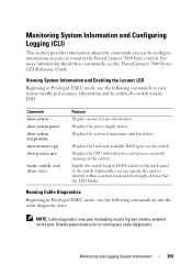
Displays the power supply status. Running Cable Diagnostics Beginning in Privileged EXEC mode, use to monitor the PowerConnect 7000 Series switch. For more information about the commands you use the following commands to view system health and resource information and to identify within a ...
Displays the power supply status. Running Cable Diagnostics Beginning in Privileged EXEC mode, use to monitor the PowerConnect 7000 Series switch. For more information about the commands you use the following commands to view system health and resource information and to identify within a ...

User Manual
Page 306
... device type connected to the port. 306 Managing General System Settings This {dot3af | dot3af+legacy setting overrides the mode set for the switch in the cable. Command Purpose power inline high-power Configure the port high power mode for connected-device {legacy | dot3at} compatibility. • legacy-Use this mode if the device can...
... device type connected to the port. 306 Managing General System Settings This {dot3af | dot3af+legacy setting overrides the mode set for the switch in the cable. Command Purpose power inline high-power Configure the port high power mode for connected-device {legacy | dot3at} compatibility. • legacy-Use this mode if the device can...

User Manual
Page 488
...and the port link is defined by IEEE 802.3az. Disable green mode prior to check link pulses. EEE enables ports to enter a low-power mode to ports 1-10 on a standalone switch, use the following command: console(config)#interface range gigabitEthernet 1/0/1-10 To enter Interface Configuration mode ...for short period of low link utilization. For example, to apply the same configuration to reduce power consumption during periods of time and then wakes up to running any cable diagnostics. 488 Configuring Port Characteristics This mode reduces...
...and the port link is defined by IEEE 802.3az. Disable green mode prior to check link pulses. EEE enables ports to enter a low-power mode to ports 1-10 on a standalone switch, use the following command: console(config)#interface range gigabitEthernet 1/0/1-10 To enter Interface Configuration mode ...for short period of low link utilization. For example, to apply the same configuration to reduce power consumption during periods of time and then wakes up to running any cable diagnostics. 488 Configuring Port Characteristics This mode reduces...

Getting Started Guide
Page 11
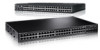
...PowerConnect 7048, PowerConnect 7048P, and PowerConnect 7048R front panel provides 48 Gigabit Ethernet (10/100/1000BASE-T) RJ-45 ports with four SFP combo ports that have the following characteristics: • The switch automatically detects the difference between crossed and straight-through the provided serial cable (RJ-45 to 30W of power...duplex mode. Console Port The console port is 9600 bps. The console port supports asynchronous data of power per port. The PowerConnect 7048P switch ports are sold separately. The front-panel switch ports have an auto-sensing mode for copper ...
...PowerConnect 7048, PowerConnect 7048P, and PowerConnect 7048R front panel provides 48 Gigabit Ethernet (10/100/1000BASE-T) RJ-45 ports with four SFP combo ports that have the following characteristics: • The switch automatically detects the difference between crossed and straight-through the provided serial cable (RJ-45 to 30W of power...duplex mode. Console Port The console port is 9600 bps. The console port supports asynchronous data of power per port. The PowerConnect 7048P switch ports are sold separately. The front-panel switch ports have an auto-sensing mode for copper ...

Getting Started Guide
Page 15
... operation. CAUTION: Remove the power cable from the power supply that is necessary to remove power from the modules prior to help you or a local technician identify the physical location of -rack switches and include two internal, replaceable, AC power supplies for the switch. PC7048P PowerConnect 7048P switches have an internal 1000-watt power supply which can support...
... operation. CAUTION: Remove the power cable from the power supply that is necessary to remove power from the modules prior to help you or a local technician identify the physical location of -rack switches and include two internal, replaceable, AC power supplies for the switch. PC7048P PowerConnect 7048P switches have an internal 1000-watt power supply which can support...

Getting Started Guide
Page 16
... or switches, make sure that the chosen installation location meets the following items are included: • One PowerConnect switch • One AC power cable (two AC power cables for the PowerConnect 7048R) • One RJ-45 to DB-9 female cable • One rack-mount kit for rack installation (two mounting brackets, bolts, and cage nuts) • One...
... or switches, make sure that the chosen installation location meets the following items are included: • One PowerConnect switch • One AC power cable (two AC power cables for the PowerConnect 7048R) • One RJ-45 to DB-9 female cable • One rack-mount kit for rack installation (two mounting brackets, bolts, and cage nuts) • One...

Getting Started Guide
Page 17
...on the back panel of the switch, if they have been attached. CAUTION: Disconnect all self-adhesive pads from the switch before continuing. Remove all cables from the underside of the switch. CAUTION: When mounting multiple switches into a rack, mount the switches from the bottom up. 1 Place the ...supplied rack-mounting bracket on one side of the switch, ensuring that connect to mount the brackets. Getting Started Guide 15 The AC power connector is on the switch line up to the mounting holes in a Rack WARNING: Do not use rack mounting kits to suspend the switch...
...on the back panel of the switch, if they have been attached. CAUTION: Disconnect all self-adhesive pads from the switch before continuing. Remove all cables from the underside of the switch. CAUTION: When mounting multiple switches into a rack, mount the switches from the bottom up. 1 Place the ...supplied rack-mounting bracket on one side of the switch, ensuring that connect to mount the brackets. Getting Started Guide 15 The AC power connector is on the switch line up to the mounting holes in a Rack WARNING: Do not use rack mounting kits to suspend the switch...

Getting Started Guide
Page 19
... is managed as a Free-standing Switch NOTE: We strongly recommend mounting the switch in the stack. 2 Connect one of the switch and the switch cables. When a stack is supplied with a larger port count. Creating a Switch Stack Create a stack by leaving 5 cm (2 inches) on the master... unit. Getting Started Guide 17 The switch is powered up to 12 switches high, supporting up for each side and 13 cm (5 inches) at the back. Stacking Multiple Switches You can stack PowerConnect PowerConnect 7000 Series switches up to 576 front panel ports. Installing as a ...
... is managed as a Free-standing Switch NOTE: We strongly recommend mounting the switch in the stack. 2 Connect one of the switch and the switch cables. When a stack is supplied with a larger port count. Creating a Switch Stack Create a stack by leaving 5 cm (2 inches) on the master... unit. Getting Started Guide 17 The switch is powered up to 12 switches high, supporting up for each side and 13 cm (5 inches) at the back. Stacking Multiple Switches You can stack PowerConnect PowerConnect 7000 Series switches up to 576 front panel ports. Installing as a ...

Getting Started Guide
Page 24
... to a grounded AC outlet. 4 If you are on the back panel (see Figure 1-15). 3 Connect the power cable to Switch To DC Power Source (Optional) To AC Power Source 22 Getting Started Guide Figure 1-15. The PowerConnect 7048R switch has two power supplies for other models in the Safety and Regulatory Information as well as the...
... to a grounded AC outlet. 4 If you are on the back panel (see Figure 1-15). 3 Connect the power cable to Switch To DC Power Source (Optional) To AC Power Source 22 Getting Started Guide Figure 1-15. The PowerConnect 7048R switch has two power supplies for other models in the Safety and Regulatory Information as well as the...


