
Command Line Interface Guide
Page 1164
console#show copper-ports cable-length command in a 100M or 1000M mode. Default Configuration This command has no default configuration. A valid Ethernet port. Example The following example displays the estimated copper cable length attached to a port. show copper-ports cable-length Use the show copper-ports cable-length Port Length [meters] ---- 1/g1 Command Mode Privileged EXEC...
console#show copper-ports cable-length command in a 100M or 1000M mode. Default Configuration This command has no default configuration. A valid Ethernet port. Example The following example displays the estimated copper cable length attached to a port. show copper-ports cable-length Use the show copper-ports cable-length Port Length [meters] ---- 1/g1 Command Mode Privileged EXEC...
Command Line Interface Guide
Page 1165
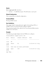
... Short 50 2004 13:32:00 23 July 1/g3 Test has not been preformed 1/g4 Open 128 2004 13:32:08 23 July 1/g5 Fiber - - console#show copper-ports tdr [interface] • interface - Example The following example displays the last TDR tests on all ports. A valid Ethernet port. The maximum length...
... Short 50 2004 13:32:00 23 July 1/g3 Test has not been preformed 1/g4 Open 128 2004 13:32:08 23 July 1/g5 Fiber - - console#show copper-ports tdr [interface] • interface - Example The following example displays the last TDR tests on all ports. A valid Ethernet port. The maximum length...

Command Line Interface Guide
Page 1167
.... Temp - Command Mode Privileged EXEC mode User Guidelines. Internally measured supply voltage Current - Loss of a copper cable attached to a port. console#test copper-port tdr 1/g3 Cable is a combo port with Time Domain Reflectometry (TDR) technology the quality and characteristics of signal test copper-port ...tdr Use the test copper-port tdr command in a report on the cable attached to diagnose with ...
.... Temp - Command Mode Privileged EXEC mode User Guidelines. Internally measured supply voltage Current - Loss of a copper cable attached to a port. console#test copper-port tdr 1/g3 Cable is a combo port with Time Domain Reflectometry (TDR) technology the quality and characteristics of signal test copper-port ...tdr Use the test copper-port tdr command in a report on the cable attached to diagnose with ...

Command Line Interface Guide
Page 1168
The following example results in a failure to port 2/g3. console#test copper-port tdr 2/g3 Can't perform the test on the cable attached to report on fiber ports 1168 PHY Diagnostics Commands
The following example results in a failure to port 2/g3. console#test copper-port tdr 2/g3 Can't perform the test on the cable attached to report on fiber ports 1168 PHY Diagnostics Commands
User's Guide
Page 4
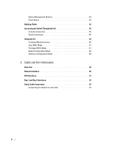
Device Management Buttons 44 Check Boxes 45 Defining Fields 45 Accessing the Switch Through the CLI 45 Console Connection 46 Telnet Connection 46 Using the CLI 46 Command Mode Overview 46 User EXEC Mode 47 Privileged EXEC Mode 47 Global Configuration Mode 48 Interface Configuration Mode 48 3 Cable and Port Information Overview 49 Ethernet Interface 50 SFP Interfaces 51 Bay 1 and Bay 2 Interfaces 52 Serial Cable Connection 52 Connecting the Switch to a Terminal 52 4
Device Management Buttons 44 Check Boxes 45 Defining Fields 45 Accessing the Switch Through the CLI 45 Console Connection 46 Telnet Connection 46 Using the CLI 46 Command Mode Overview 46 User EXEC Mode 47 Privileged EXEC Mode 47 Global Configuration Mode 48 Interface Configuration Mode 48 3 Cable and Port Information Overview 49 Ethernet Interface 50 SFP Interfaces 51 Bay 1 and Bay 2 Interfaces 52 Serial Cable Connection 52 Connecting the Switch to a Terminal 52 4
User's Guide
Page 45
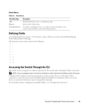
... a direct connection to the console port or through a Telnet connection, ensure the device has an IP address defined and that takes you are managing a stack, ensure the serial interface cable is similar to entering commands on the Dell OpenManage Switch Administrator Web page...., unless otherwise noted on a Linux system. Removes the selected item. Using the CLI is attached to a configuration page. Using Dell™ OpenManage™ Switch Administrator 45 Check Boxes Check Box Type Add Remove General selection Description Hyperlink that the workstation used except...
... a direct connection to the console port or through a Telnet connection, ensure the device has an IP address defined and that takes you are managing a stack, ensure the serial interface cable is similar to entering commands on the Dell OpenManage Switch Administrator Web page...., unless otherwise noted on a Linux system. Removes the selected item. Using the CLI is attached to a configuration page. Using Dell™ OpenManage™ Switch Administrator 45 Check Boxes Check Box Type Add Remove General selection Description Hyperlink that the workstation used except...
User's Guide
Page 46
... Command Mode Overview The CLI is a terminal emulation TCP/IP protocol. Otherwise, the user is powered up enable passwords. 46 Using Dell™ OpenManage™ Switch Administrator Turn on setting up for the first time, the switches elect the Master Switch, which displays as... mode to four simultaneous Telnet sessions. Only a limited subset of the required console cable. 1. When finished, exit the session with the User: login prompt. Your switch supports up . Console Connection See "Serial Cable Connection" on page 52 for a description of commands are installing a stack ...
... Command Mode Overview The CLI is a terminal emulation TCP/IP protocol. Otherwise, the user is powered up enable passwords. 46 Using Dell™ OpenManage™ Switch Administrator Turn on setting up for the first time, the switches elect the Master Switch, which displays as... mode to four simultaneous Telnet sessions. Only a limited subset of the required console cable. 1. When finished, exit the session with the User: login prompt. Your switch supports up . Console Connection See "Serial Cable Connection" on page 52 for a description of commands are installing a stack ...
User's Guide
Page 51
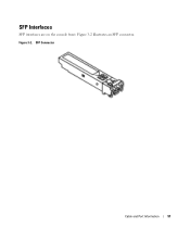
Figure 3-2. SFP Connector Cable and Port Information 51 SFP Interfaces SFP interfaces are on the console front. Figure 3-2 illustrates an SFP connector.
Figure 3-2. SFP Connector Cable and Port Information 51 SFP Interfaces SFP interfaces are on the console front. Figure 3-2 illustrates an SFP connector.

User's Guide
Page 52
.... Serial Connection to Switch Serial Connector to female DB-9 crossover cable. Figure 3-4. The switch's serial cable is a female to Console 52 Cable and Port Information If you are configuring a stack, connect the interface cable to the switch's serial port. 3. Figure 3-3. Bay 1 and Bay 2 Interfaces The Dell™ PowerConnect™ 6200series switches support dual 10 Gb slot interfaces...
.... Serial Connection to Switch Serial Connector to female DB-9 crossover cable. Figure 3-4. The switch's serial cable is a female to Console 52 Cable and Port Information If you are configuring a stack, connect the interface cable to the switch's serial port. 3. Figure 3-3. Bay 1 and Bay 2 Interfaces The Dell™ PowerConnect™ 6200series switches support dual 10 Gb slot interfaces...

User's Guide
Page 61
... to the Master Switch. NOTE: If you need to assemble and cable the stack before powering up for management through a serial interface. Connect the terminal to use the CLI. Hardware Description 61 NOTE: The console port supports asynchronous data of switches, you are installing a stack of... have the following physical dimensions: • 440 x 460 x 44 mm (W x D x H). • 17.32 x 18.11 x 1.73 inch (W x D x H). Console (RS-232) Port The console (RS-232) port is used only for the first time, the switches elect a Master Switch, which may occupy any location in the stack...
... to the Master Switch. NOTE: If you need to assemble and cable the stack before powering up for management through a serial interface. Connect the terminal to use the CLI. Hardware Description 61 NOTE: The console port supports asynchronous data of switches, you are installing a stack of... have the following physical dimensions: • 440 x 460 x 44 mm (W x D x H). • 17.32 x 18.11 x 1.73 inch (W x D x H). Console (RS-232) Port The console (RS-232) port is used only for the first time, the switches elect a Master Switch, which may occupy any location in the stack...
User's Guide
Page 74
... consists of the unit • Assigned IP address for the switch for changing the default baud rate using CLI commands: console#configure console(config)#line console console(config-line)#speed 115200 NOTE: Remember to set the baud rate on the terminal emulator software on your workstation to its ... for downloading embedded software and configuring the switch: • ASCII terminal (or emulation) connected to the serial port (cross-cable) in the rear of adjusting the ASCII configuration files so that are delivered with Telnet, SSH, and so forth 74 Configuring Dell PowerConnect
... consists of the unit • Assigned IP address for the switch for changing the default baud rate using CLI commands: console#configure console(config)#line console console(config-line)#speed 115200 NOTE: Remember to set the baud rate on the terminal emulator software on your workstation to its ... for downloading embedded software and configuring the switch: • ASCII terminal (or emulation) connected to the serial port (cross-cable) in the rear of adjusting the ASCII configuration files so that are delivered with Telnet, SSH, and so forth 74 Configuring Dell PowerConnect
User's Guide
Page 105
Set the serial console with the following settings and select the appropriate COM port. Network adapter card - Sample Configuration Process This section provides the basic steps required to ... file - See "Device Default Settings." ASCII terminal application (for the purpose of switch when powered up - A browser application • One Null Modem F2F cable • Straight or cross UTP (category 5) cable(s) Initial Connection 1. Configuring Dell PowerConnect 105 This section does not explain the various configurations available on the switch or the relevant commands.
Set the serial console with the following settings and select the appropriate COM port. Network adapter card - Sample Configuration Process This section provides the basic steps required to ... file - See "Device Default Settings." ASCII terminal application (for the purpose of switch when powered up - A browser application • One Null Modem F2F cable • Straight or cross UTP (category 5) cable(s) Initial Connection 1. Configuring Dell PowerConnect 105 This section does not explain the various configurations available on the switch or the relevant commands.
User's Guide
Page 111
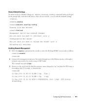
...Privileged EXEC screen mode as shown below: console# 01-Jan-2000 01:43:03 %LINK-I-Up: Vlan 1 01-Jan-2000 01:43:03 %LINK-I-Up: 1/xg1 01-Jan-2000 01:43:34 %STP-I-PORTSTATUS: Port 1/xg1: STP status Forwarding Configuring Dell PowerConnect 111 Are you sure you want to ... the interface status changed to device default settings use delete startup-config command at the console to the switch, using a CAT5 Cable. Enabling Remote Management 1. it is forwarding (after 30 seconds), as follows: console>enable console# 2. Device Default Settings To return to "up" and that the STP status is ...
...Privileged EXEC screen mode as shown below: console# 01-Jan-2000 01:43:03 %LINK-I-Up: Vlan 1 01-Jan-2000 01:43:03 %LINK-I-Up: 1/xg1 01-Jan-2000 01:43:34 %STP-I-PORTSTATUS: Port 1/xg1: STP status Forwarding Configuring Dell PowerConnect 111 Are you sure you want to ... the interface status changed to device default settings use delete startup-config command at the console to the switch, using a CAT5 Cable. Enabling Remote Management 1. it is forwarding (after 30 seconds), as follows: console>enable console# 2. Device Default Settings To return to "up" and that the STP status is ...

Getting Started Guide
Page 12
... product before powering up and configuring the stack. 1 Connect an RS-232 crossover cable to use the console port on the rear of the user documentation from the Dell Support website at support.dell.com. NOTE: Read the release notes for Function, Arrow, and Ctrl keys. ...with a female DB-9 connector for the console port and the appropriate connector for Terminal keys (not Microsoft® Windows® keys). You can download the release notes from the Dell Support website at support.dell.com. www.dell.com | support.dell.com Starting and Configuring the Switch After ...
... product before powering up and configuring the stack. 1 Connect an RS-232 crossover cable to use the console port on the rear of the user documentation from the Dell Support website at support.dell.com. NOTE: Read the release notes for Function, Arrow, and Ctrl keys. ...with a female DB-9 connector for the console port and the appropriate connector for Terminal keys (not Microsoft® Windows® keys). You can download the release notes from the Dell Support website at support.dell.com. www.dell.com | support.dell.com Starting and Configuring the Switch After ...
Getting Started Guide
Page 13
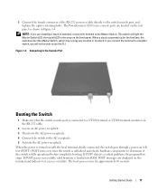
... in the array on selftest (POST). Connecting to the Console Port Booting the Switch 1 Make sure that the switch console port is connected to a VT100 terminal or VT100 terminal emulator via the RS-232 cable. 2 Locate an AC power receptacle. 3 Deactivate the ...AC power receptacle. 4 Connect the switch to determine if the switch is turned on with the local terminal already connected, the switch goes through a power-on the front panel. When the power is fully operational before completely booting. The PowerConnect 6200 series console...
... in the array on selftest (POST). Connecting to the Console Port Booting the Switch 1 Make sure that the switch console port is connected to a VT100 terminal or VT100 terminal emulator via the RS-232 cable. 2 Locate an AC power receptacle. 3 Deactivate the ...AC power receptacle. 4 Connect the switch to determine if the switch is turned on with the local terminal already connected, the switch goes through a power-on the front panel. When the power is fully operational before completely booting. The PowerConnect 6200 series console...

Release Notes
Page 34
... switch to ports which Network is intermittent and only observable when connected to a D-Link DES1008. All characters following the '!' File Management Description Error displayed on console while applying configuration for the non-existent ports. Cable Diagnostics Description Cable Length Diagnostic shows result as a comment. The '!'
... switch to ports which Network is intermittent and only observable when connected to a D-Link DES1008. All characters following the '!' File Management Description Error displayed on console while applying configuration for the non-existent ports. Cable Diagnostics Description Cable Length Diagnostic shows result as a comment. The '!'

Configuration Guide
Page 26
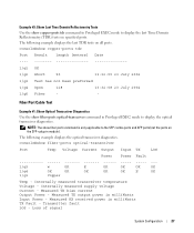
... System > Diagnostics. Example #2: Show Copper Cable Length Use the show copper-ports cable-length command in Privileged EXEC mode to display the estimated copper cable length attached to all ports. Example #1: Cable Test for Copper Ports console#test copper-port tdr 1/g1 Cable Status Short Cable Length 5m console#show copper-ports cable-length Port Length [meters] ---- 1/g1 The...
... System > Diagnostics. Example #2: Show Copper Cable Length Use the show copper-ports cable-length command in Privileged EXEC mode to display the estimated copper cable length attached to all ports. Example #1: Cable Test for Copper Ports console#test copper-port tdr 1/g1 Cable Status Short Cable Length 5m console#show copper-ports cable-length Port Length [meters] ---- 1/g1 The...
Configuration Guide
Page 27
...SFP combo ports and XFP ports (not the ports on the SFP+ plug-in module). Loss of signal System Configuration 27 Fiber Port Cable Test Example #1: Show Optical Transceiver Diagnostics Use the show copper-ports tdr command in Privileged EXEC mode to display the last Time Domain Reflectometry...#3: Show Last Time Domain Reflectometry Tests Use the show fiber-ports optical-transceiver command in Privileged EXEC mode to display the optical transceiver diagnostics. console#show copper-ports tdr Port Result Length [meters] Date 1/g1 OK 1/g2 Short 50 13:32:00 23 July 2004 1/g3 Test has ...
...SFP combo ports and XFP ports (not the ports on the SFP+ plug-in module). Loss of signal System Configuration 27 Fiber Port Cable Test Example #1: Show Optical Transceiver Diagnostics Use the show copper-ports tdr command in Privileged EXEC mode to display the last Time Domain Reflectometry...#3: Show Last Time Domain Reflectometry Tests Use the show fiber-ports optical-transceiver command in Privileged EXEC mode to display the optical transceiver diagnostics. console#show copper-ports tdr Port Result Length [meters] Date 1/g1 OK 1/g2 Short 50 13:32:00 23 July 2004 1/g3 Test has ...


