
Command Line Interface Guide
Page 436
...)# hashing-mode Use the hashing-mode command to set the hashing algorithm on subsequent interfaces. Range: 1-6: • 1 - Destination MAC, VLAN, EtherType, source module, and port ID • 3 - Source/destination MAC, VLAN, EtherType, and source MODID/port • 6 - Mode value in the range of the... command on trunk ports. Source MAC, VLAN, EtherType, source module, and port ID • 2 - Syntax hashing-mode mode • mode - Source IP and source TCP/UDP port • 4 - Destination IP...
...)# hashing-mode Use the hashing-mode command to set the hashing algorithm on subsequent interfaces. Range: 1-6: • 1 - Destination MAC, VLAN, EtherType, source module, and port ID • 3 - Source/destination MAC, VLAN, EtherType, and source MODID/port • 6 - Mode value in the range of the... command on trunk ports. Source MAC, VLAN, EtherType, source module, and port ID • 2 - Syntax hashing-mode mode • mode - Source IP and source TCP/UDP port • 4 - Destination IP...

Command Line Interface Guide
Page 439
Destination IP and destination TCP/UDP port 5 - Destination MAC, VLAN, EtherType, source module and port Id 3 - Syntax show statistics port-channel command in Privileged EXEC mode to display. Command Mode Privileged EXEC mode Port Channel Commands... 439 Valid port-channel number channel to display statistics about a specific port-channel. Source MAC, VLAN, EtherType, source module and port Id 2 - Source/Destination IP and source/destination TCP/UDP port show statistics port-channel Use the show statistics port-channel port-channel-...
Destination IP and destination TCP/UDP port 5 - Destination MAC, VLAN, EtherType, source module and port Id 3 - Syntax show statistics port-channel command in Privileged EXEC mode to display. Command Mode Privileged EXEC mode Port Channel Commands... 439 Valid port-channel number channel to display statistics about a specific port-channel. Source MAC, VLAN, EtherType, source module and port Id 2 - Source/Destination IP and source/destination TCP/UDP port show statistics port-channel Use the show statistics port-channel port-channel-...
Command Line Interface Guide
Page 1165
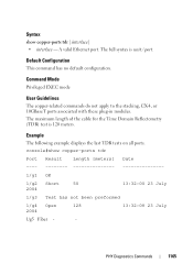
... Mode Privileged EXEC mode User Guidelines The copper-related commands do not apply to the stacking, CX-4, or 10GBaseT ports associated with these plug-in modules. The maximum length of the cable for the Time Domain Reflectometry (TDR) test is unit / port. The full syntax is 120 meters. Example The following...
... Mode Privileged EXEC mode User Guidelines The copper-related commands do not apply to the stacking, CX-4, or 10GBaseT ports associated with these plug-in modules. The maximum length of the cable for the Time Domain Reflectometry (TDR) test is unit / port. The full syntax is 120 meters. Example The following...
Command Line Interface Guide
Page 1166
... fiber-ports optical-transceiver command in Privileged EXEC mode to the SFP combo ports and XFP ports (not the ports on the SFP+ plug-in module).
... fiber-ports optical-transceiver command in Privileged EXEC mode to the SFP combo ports and XFP ports (not the ports on the SFP+ plug-in module).
Command Line Interface Guide
Page 1338
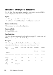
... this command to reset to configure the standby in the stack. (Range: 1-12 maximum. Use the no default configuration. The range is used with a CX-4 module, the ports will not change the operating mode of this command is limited to Ethernet mode upon reboot. Syntax standby unit • unit - Valid unit...
... this command to reset to configure the standby in the stack. (Range: 1-12 maximum. Use the no default configuration. The range is used with a CX-4 module, the ports will not change the operating mode of this command is limited to Ethernet mode upon reboot. Syntax standby unit • unit - Valid unit...
User's Guide
Page 5
... 62 Stacking Standby 63 LED Definitions 64 SFP Port LEDs 64 SFP+ Port LEDs 65 XFP Module Port LEDs 65 10/100/1000 Base-T Port LEDs 65 System LEDs 67 Stacking LEDs 68 5 Configuring Dell PowerConnect Overview 71 Starting the CLI 72 General Configuration Information 74 Terminal Connection Configuration 74 Baud Rate 74...
... 62 Stacking Standby 63 LED Definitions 64 SFP Port LEDs 64 SFP+ Port LEDs 65 XFP Module Port LEDs 65 10/100/1000 Base-T Port LEDs 65 System LEDs 67 Stacking LEDs 68 5 Configuring Dell PowerConnect Overview 71 Starting the CLI 72 General Configuration Information 74 Terminal Connection Configuration 74 Baud Rate 74...

User's Guide
Page 22
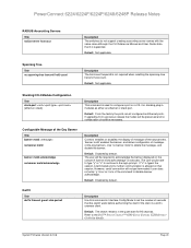
Non-stop Forwarding This feature enables a stack to continue forwarding packets when the stack management unit fails due to its module ID. By default, the module will be configured to either role (Ethernet or Stacking). Configurable CX-4/Stacking Modules This feature allows the stacking and CX-4 plug-in modules to be required for the change to take effect. Upon changing the role of a module, a reboot will function according to a power failure, hardware failure, or software fault. 22 Introduction
Non-stop Forwarding This feature enables a stack to continue forwarding packets when the stack management unit fails due to its module ID. By default, the module will be configured to either role (Ethernet or Stacking). Configurable CX-4/Stacking Modules This feature allows the stacking and CX-4 plug-in modules to be required for the change to take effect. Upon changing the role of a module, a reboot will function according to a power failure, hardware failure, or software fault. 22 Introduction

User's Guide
Page 52
Bay 1 and Bay 2 Interfaces The Dell™ PowerConnect™ 6200series switches support dual 10 Gb slot interfaces. Figure 3-3. Connecting the Switch to the serial port ...female DB-9 crossover cable. The switch's serial cable is a female to the switch's serial port. 3. Bay 1 and Bay 2 PowerConnect 6200 Series 10 Gb Slots Serial Cable Connection You can use a computer running terminal emulation software). These interfaces can also use the supplied... setup and configuration (You can operate at 10 Gbps when supporting optional SFP+, CX4, XFP, and 10GBase-T modules. Figure 3-4.
Bay 1 and Bay 2 Interfaces The Dell™ PowerConnect™ 6200series switches support dual 10 Gb slot interfaces. Figure 3-3. Connecting the Switch to the serial port ...female DB-9 crossover cable. The switch's serial cable is a female to the switch's serial port. 3. Bay 1 and Bay 2 PowerConnect 6200 Series 10 Gb Slots Serial Cable Connection You can use a computer running terminal emulation software). These interfaces can also use the supplied... setup and configuration (You can operate at 10 Gbps when supporting optional SFP+, CX4, XFP, and 10GBase-T modules. Figure 3-4.
User's Guide
Page 58
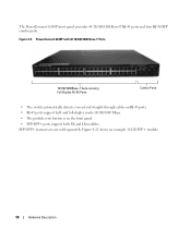
... front panel provides 44 10/100/1000 Base-T RJ-45 ports and four RJ-45/SFP combo ports. PowerConnect 6248P with 48 10/100/1000 Base-T Ports 10/100/1000Base-T Auto-sensing Full Duplex RJ-45 Ports Combo Ports • The switch automatically detects ...crossed and straight-through cables on the front panel. • SFP/SFP+ ports support both SX and LX modules. and full-duplex mode 10/100/1000 Mbps. • The pinhole reset button is on RJ-45 ports. • RJ-45 ports support half- Figure...
... front panel provides 44 10/100/1000 Base-T RJ-45 ports and four RJ-45/SFP combo ports. PowerConnect 6248P with 48 10/100/1000 Base-T Ports 10/100/1000Base-T Auto-sensing Full Duplex RJ-45 Ports Combo Ports • The switch automatically detects ...crossed and straight-through cables on the front panel. • SFP/SFP+ ports support both SX and LX modules. and full-duplex mode 10/100/1000 Mbps. • The pinhole reset button is on RJ-45 ports. • RJ-45 ports support half- Figure...
User's Guide
Page 59
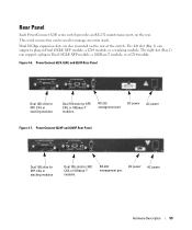
... rear. The right slot (Bay 2) can support a plug-in Dual 10GbE XFP module, a 10GBase-T module, or a CX4 module. Figure 4-6. PowerConnect 6224, 6248, and 6224F Rear Panel Dual 10G slots for XFP, CX4, or stacking modules Dual 10G slots for XFP, CX4, or 10Gbase-T modules. PowerConnect 6224P and 6248P Rear Panel Dual 10G slots for XFP, CX4, or stacking...
... rear. The right slot (Bay 2) can support a plug-in Dual 10GbE XFP module, a 10GBase-T module, or a CX4 module. Figure 4-6. PowerConnect 6224, 6248, and 6224F Rear Panel Dual 10G slots for XFP, CX4, or stacking modules Dual 10G slots for XFP, CX4, or 10Gbase-T modules. PowerConnect 6224P and 6248P Rear Panel Dual 10G slots for XFP, CX4, or stacking...
User's Guide
Page 60
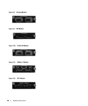
Figure 4-8. SFP+ Module 60 Hardware Description XFP Module Figure 4-10. 10 GbE CX4 Module Figure 4-11. 10GBase-T Module Figure 4-12. Stacking Module Figure 4-9.
Figure 4-8. SFP+ Module 60 Hardware Description XFP Module Figure 4-10. 10 GbE CX4 Module Figure 4-11. 10GBase-T Module Figure 4-12. Stacking Module Figure 4-9.
User's Guide
Page 62
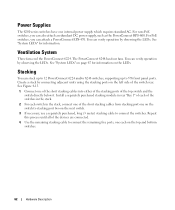
... switch. 3. See Figure 4-13. 1. Use the remaining stacking cable to connect the switches. For PoE switches, you can attach a PowerConnect EPS-470. Ventilation System Three fans cool the PowerConnect 6224. Install a separately purchased stacking module in the stack. 2. Connect one internal power supply which requires standard AC. For non-PoE switches, you can also...
... switch. 3. See Figure 4-13. 1. Use the remaining stacking cable to connect the switches. For PoE switches, you can attach a PowerConnect EPS-470. Ventilation System Three fans cool the PowerConnect 6224. Install a separately purchased stacking module in the stack. 2. Connect one internal power supply which requires standard AC. For non-PoE switches, you can also...
User's Guide
Page 65
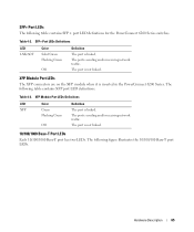
The port is linked. Table 4-3. SFP+ Port LEDs The following table contains XFP port LED definitions. XFP Module Port LEDs Definitions LED Color Definition XFP Green The port is not linked. Off The port is linked. SFP+ Port LEDs Definitions LED ... has two LEDs. Flashing Green The port is sending and/or receiving network traffic. The following table contains SFP+ port LED definitions for the PowerConnect 6200 Series switches. Hardware Description 65 The following figure illustrates the 10/100/100 Base-T port LEDs. The port is sending and/or receiving network...
The port is linked. Table 4-3. SFP+ Port LEDs The following table contains XFP port LED definitions. XFP Module Port LEDs Definitions LED Color Definition XFP Green The port is not linked. Off The port is linked. SFP+ Port LEDs Definitions LED ... has two LEDs. Flashing Green The port is sending and/or receiving network traffic. The following table contains SFP+ port LED definitions for the PowerConnect 6200 Series switches. Hardware Description 65 The following figure illustrates the 10/100/100 Base-T port LEDs. The port is sending and/or receiving network...

User's Guide
Page 715
... commands that perform this feature. Configures the Register Threshold rate for the RP router to switch to set the administrative status of the multicast forwarding module. • Table Maximum Entry Count - Configuring IP Multicast 715 The default is updated. Click Apply Changes. Set the administrative mode of multicast route entries currently...
... commands that perform this feature. Configures the Register Threshold rate for the RP router to switch to set the administrative status of the multicast forwarding module. • Table Maximum Entry Count - Configuring IP Multicast 715 The default is updated. Click Apply Changes. Set the administrative mode of multicast route entries currently...
Getting Started Guide
Page 10
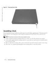
...connecting adjacent units using the stacking ports on the left side of the switches to be stacked. 2 Use the cables supplied with the stacking modules to connect from the last switch to the first switch to create a loop. 4 If necessary, use a separately purchased three-meter stacking ...the next until all switches are added to 576 front panel ports. Connecting Power Cable Assembling a Stack You can stack PowerConnect 6200 series switches up to 12 switches high, supporting up to a stack. 1 Install a separately purchased stacking module in rear "Bay 1" in each of the switch rear. www...
...connecting adjacent units using the stacking ports on the left side of the switches to be stacked. 2 Use the cables supplied with the stacking modules to connect from the last switch to the first switch to create a loop. 4 If necessary, use a separately purchased three-meter stacking ...the next until all switches are added to 576 front panel ports. Connecting Power Cable Assembling a Stack You can stack PowerConnect 6200 series switches up to 12 switches high, supporting up to a stack. 1 Install a separately purchased stacking module in rear "Bay 1" in each of the switch rear. www...
Release Notes
Page 5
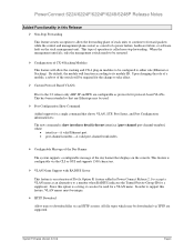
...Modules This feature will allow the forwarding plane of stack units to continue to forward packets while the control and management planes restart as a result of a power failure, hardware failure, or software fault on the console. This has been extended so that displays on the stack management unit. PowerConnect 6224...either role (Ethernet or Stacking). In order to support this option is an extension of Dot1x Option 81 feature added in modules to its module ID. This type of operation is show interfaces detail {ethernet interface | port-channel port-channel-number} where • ...
...Modules This feature will allow the forwarding plane of stack units to continue to forward packets while the control and management planes restart as a result of a power failure, hardware failure, or software fault on the console. This has been extended so that displays on the stack management unit. PowerConnect 6224...either role (Ethernet or Stacking). In order to support this option is an extension of Dot1x Option 81 feature added in modules to its module ID. This type of operation is show interfaces detail {ethernet interface | port-channel port-channel-number} where • ...
Release Notes
Page 25
... configure a port on a CX-4 or stacking plug-in the quiet state for details. Default: The switch remains in modules as Ethernet ports. If upgrading from a previous release the modes will not get terminated if user does not enter 'y'. Use...Dell™ PowerConnect™ 6200 Series Systems CLI Reference Guide for 90 seconds. Default: From the factory the ports are all configured as either an ethernet or stack port. If "n" is typed, the session is terminated and no configuration should be required to acknowledge the banner displayed on that session. PowerConnect 6224...
... configure a port on a CX-4 or stacking plug-in the quiet state for details. Default: The switch remains in modules as Ethernet ports. If upgrading from a previous release the modes will not get terminated if user does not enter 'y'. Use...Dell™ PowerConnect™ 6200 Series Systems CLI Reference Guide for 90 seconds. Default: From the factory the ports are all configured as either an ethernet or stack port. If "n" is typed, the session is terminated and no configuration should be required to acknowledge the banner displayed on that session. PowerConnect 6224...
Configuration Guide
Page 25
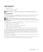
...-related commands do not apply to the stacking, 10G BaseT, or CX-4 ports associated with these plug-in fact be determined. The cable may in modules. System Configuration 25 Cable Diagnostics This section describes: • "Copper Port Cable Test" on page 25 • "Fiber Port Cable Test" on page 27 NOTE...
...-related commands do not apply to the stacking, 10G BaseT, or CX-4 ports associated with these plug-in fact be determined. The cable may in modules. System Configuration 25 Cable Diagnostics This section describes: • "Copper Port Cable Test" on page 25 • "Fiber Port Cable Test" on page 27 NOTE...
Configuration Guide
Page 27
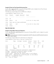
... in milliWatts Input Power - The following example displays the optical transceiver diagnostics. The following example displays the last TDR tests on the SFP+ plug-in module). Internally measured supply voltage Current - Transmitter fault LOS - Loss of signal System Configuration 27 console#show fiber-ports optical-transceiver Port Temp Voltage Current Output...
... in milliWatts Input Power - The following example displays the optical transceiver diagnostics. The following example displays the last TDR tests on the SFP+ plug-in module). Internally measured supply voltage Current - Transmitter fault LOS - Loss of signal System Configuration 27 console#show fiber-ports optical-transceiver Port Temp Voltage Current Output...


